KA2DWLG122B1802.11g/2.4GHz Wireless USB Adapter
D-Link Corporation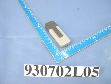
Click to zoom
Application Details
- Equipment Class
- DTS - Digital Transmission System
- Date of Grant
- Aug 02, 2004
- Application Purpose
- Original Equipment
- Date of Application
- Aug 02, 2004
- Equipment Note
- 802.11g/2.4GHz Wireless USB Adapter
- Frequency Range
- 2412.00000000 - 2462.00000000
- Company
- D-Link Corporation
- Country
- United States
Documents & Files
Document Text
Text extracted from the exhibit documents filed with the FCC. Open a document above to read the original.
Users Manual
1 AirPlus G TM High Speed 802.11g USB Wireless Adapter DWL-G122 If any of the above items are missing, please contact your reseller. This product works with the following operating system software: Windows XP, Windows 2000, Windows Me, Windows 98SE Before You Begin You must have at least the following: •You will need a computer with an available USB port to connect the DWL-G122 Wireless USB adapter. •At least a 500 MHz processor and 62 MB of memory •An 802.11b or 802.11g Access Point (for Infrastructure Mode) or another 802. 11b or 802.11g wireless adapter (for Ad-Hoc; Peer-to-Peer networking mode.) •Properly installed and working USB Controller. DWL-G122 Wireless USB Adapter Check Your Package Contents These are the items included with your DWL-G122 purchase: Cradle CD-ROM (containing Drivers, Manual and Warranty) @2004 D-Link Systems, Inc. All rights reserved. Trademarks or registered trademarks are the property of their respective holders. Software and specifications subject to change without notice. 2 USB Connector Connects to Yours desktop or laptop computerl. DWL-G122 Overview The Install Screen will appear. Turn on the computer and Insert the D- Link AirPuls G TM DWL- G122 Driver CD in the CD-ROM drive. The step-by-step instructions that follow are shown in Windows XP. The steps and screens are similar for the other Windows operating systems Insert the D-Link CD-ROM Into Your Computer Do NOT install the DWL-G122 USB Adapter into your computer before installing the driver software on the D-Link CD! Click Install Drivers Link/Power LED Link - Indicates that the DWL-G122 is properly installed in the computer. Power - blinks when data is being transmitted through the wireless connection. Antenna Used to wirelessly connect to 802.11b or 802.11g networks. 3 Click Next Click Next If the CD Autorun function does not automatically start on your computer , type “D:\Driver\Setup.exe” If it does start, proceed to the next screen. The letter “D” represents the letter of the CD-ROM drive. Your CD-ROM drive may be a different drive letter. Click Next 4 Click Finish Click No, I will restart my computer later Shut down your computer Click Continue Anyway Installing the DWL-G122 Wireless USB Adapter to Your Laptop Computer A.Make sure to turn off your computer. B.Insert one end of the USB Adapter into the provided USB cable and plug the other end into your computer’s USB Port. 5 Click Finish Restart Your Computer When you restart your computer this Found New Hardware Wizard (Windows XP) screen will appear: Select Install the software automatically (Recommended) Click Next Windows XP will automatically load the driver files. Click Continue Anyway 6 For Windows 2000, this Digital Signature Not Found screen may appear during the installation. Click Yes to continue the installation Your Installation is Complete! After you’ve continued in Windows XP (or after the computer restarts in the other Windows operating systems), the D-Link AirPlus DWL-G122 Con- figuration Utility will automatically start and the utility icon will appear in the bottom right hand corner of the desktop screen (systray). If this icon appears GREEN, then you have successfully installed the DWL-G122, are connected to a wireless network and are ready to communicate! Double-click the utility icon to use the configuration utility. For Windows Me and 98, this screen may appear. Click Yes to finalize the installation 7 Appendix Using the Configuration Utility A. Status: Displays the MAC Address of the Access Point that is associated with the DWL-G122. B. SSID: The Service Set Identifier is the name assigned to the wireless network. The factory SSID setting is set to default. C. Frequency: Displays the current frequency used by the adapter. D. Wireless Mode: The factory setting is set to Infrastructure. Ad-Hoc mode is used for peer-to-peer networking. F. Connection Info: Displays connected or authenticated information. I. Signal Strength / Link Quality: Repre- sents the wireless signal quality and strength between the access point and the DWL- G122. The percentage coincides with the graphical bar. H. Channel: Displays the channel information. By default, the channel is set to 6. Please note that the DWL- G122 will automati- cally adjust channel depending on the Access Point. E. Encryption: Displays the current encryption status of the wireless connection. G. TxRate: The default setting is Auto; meaning, TxRate settings are automatically determined by the DWL-G122 depending on the distance from the access point. J. Packet Count: Graphically displays the statistics of data transmitted and received. J G I A B C D E F H 8 Appendix Using the Configuration Utility (cont.) K L O L. Wireless Mode: The factory setting is set to Infrastructure. Ad-Hoc mode is used for peer-to-peer networking. N. Authentication: You can specify the authentication mode for the wireless network. The default setting is set to Open Authentica- tion. O. Key Length: When encryption is enabled, you will have the option to specify the level and key format of the encryption used. Select the appropriate Key Index : 1-4 and enter ACSII or hexadecimal digits in the appropriate field. K. SSID: The Service Set Identifier is the name as- signed to the wireless network. The factory SSID setting is set to default. Make changes here to match the SSID on existing Wireless Router or Access Point. M. Data Encryption: The default setting is set to Disabled. The adapter supports WEP when encryption is enabled. M N P P. IEEE 802.1x: When encryption is enabled, you will have the option to specify the level and key format of the encryption used. Select the appropriate Key Index : 1-4 and enter ACSII or hexadecimal digits in the appropriate field. Federal Communication Commission Interference Statement This equipment has been tested and found to comply with the limits for a Class B digital device, pursuant to Part 15 of the FCC Rules. These limits are designed to provide reasonable protection …
Text truncated - open the document above for the full version.
Cover Letter(s)
D-Link Corporation NO.8,Li Hsing Rd VII ,SCIENCE-BASED INDUSTRIAL PARK,HSINCHU,TAIWAN,R.O.C. TEL: ++886 3-563-6666 FAX: +886 3-578-1861 FCC ID: KA2DWLG122B1 Federal Communications Commission Authorization and Evaluation Division Confidentiality Request Pursuant to Sections 0.457 and 0.459 of the Commission’s Rules, the Applicant hereby requests confidential treatment of information accompanying this Application as outlined below: Schematics Block Diagram The above materials contain trade secrets and proprietary information not customarily released to the public. The public disclosure of these matters might be harmful to the Applicant and provide unjustified benefits to its competitors. The Applicant understands that pursuant to Rule 0.457, disclosure of this Application and all accompanying documentation will not be made before the date of the Grant for this application. Sincerely, --------------------------------------------------- Leeming Li / Manager D-Link Corporation Tel: 886-3-563-6666 ext.6613 Fax: 886-3-578-1861 E-mail: [email protected]
Cover Letter(s)
D-Link Corporation NO.8, Li Hsing Rd VII, SCIENCE-BASED INDUSTRIAL PARK, HSINCHU, TAIWAN, R.O.C. TEL: ++886 3-563-6666 FAX: +886 3-578-1861 POWER OF ATTORNEY To whom it may concern: We, the undersigned, D-Link Corporation, hereby authorize Advance Data Technology Corp. (ADT) of Taiwan to act on our behalf in all matters relating to all processes required in the FCC Part 15C. Any and all acts carried out by ADT on our behalf shall have the same effects as acts of our own. If you have any questions regarding the authorization, please don’t hesitate to contact us. Thank you! Sincerely yours, ------------------------------------------------------------------- Leeming Li / Manager D-Link Corporation Tel: 886-3-563-6666 ext.6613 Fax: 886-3-578-1861 E-mail: [email protected]
Cover Letter(s)
FEDERAL COMMUNICATIONS COMMISSION DECLARATION OF CONFORMITY (DoC) FOR THE FOLLOWING EQUIPMENT: PRODUCT NAME: 802.11g/2.4GHz Wireless USB Adapter (Receiver Part) MODEL NO.: DWL-G122 TRADE NAME: D-Link IS HEREWITH CONFIRMED AND FOUND TO COMPLY WITH THE REQUIREMENTS OF CFR 47 PART 15 REGULATION. THE RESULTS OF ELECTROMAGNETIC EMISSION EVALUATION ARE SHOWN IN THE REPORT NO.: D930702L05 THIS DEVICE COMPLIES WITH PART 15 OF THE FCC RULES. OPERATION IS SUBJECT TO THE FOLLOWING TWO CONDITIONS: (1) THIS DEVICE MAY NOT CAUSE HARMFUL INTERFERENCE AND, (2) THIS DEVICE MUST ACCEPT ANY INTERFERENCE RECEIVED, INCLUDING INTERFERENCE THAT MAY CAUSE UNDESIRED OPERATION. THE FOLLOWING LOCAL MANUFACTURER/IMPORTER IS RESPONSIBLE FOR THIS DECLARATION: D-Link Systems, Inc. (COMPANY NAME) 53 Discovery Drive, Irvine CA 92618 U.S.A (COMPANY ADDRESS) TEL: 949-708-0805 FAX: 949-272-4629 Kenny Huang, Director of Product Management (NAME) (TITLE) (SIGNATURE) (DATE)
External Photos
Page 1 CONSTRUCTION PHOTOS OF EUT Page 2
ID Label/Location Info
(Fig. 1) FCC ID: KA2DWLG122B1 LABEL LOCATION Label
ID Label/Location Info
~1489340.jpg (382 x 125 x 24)
Internal Photos
Page 4 Page 5 Page 6 Page 7 Page 8 Page 9
Operational Description
FCC ID: KA2DWLG122B1 Report No. 930702L05 Operational Description This device is a 802.11g/2.4GHz Wireless USB Adapter, the maximum data rate could be up to 54Mbps which OFDM technique will be applied. If the signal to noise radio is too poor which could not support 54Mbps, the 11Mbps data rate with CCK technique will be applied. The transmitter of the EUT (802.11g/2.4GHz Wireless USB Adapter) is powered from host equipment. The antenna type used in this product is Chip Antenna without connector . The other instruction, please have a look at the users manual.
RF Exposure Info
FCC ID: KA2DWLG122B1 Report No.: SA930702L051Issued: July 16, 2004 SAR TEST REPORT REPORT NO.: SA930702L05 MODEL NO.: DWL-G122 RECEIVED: July 02, 2004 TESTED: July 14, 2004 APPLICANT: D-LINK CORPORATION ADDRESS: No. 8, Li-shing Road VII, Science-based Industrial Park, Hsinchu Taiwan, R. O. C ISSUED BY: Advance Data Technology Corporation LAB LOCATION: No. 19, Hwa Ya 2nd rd., Kueishan, Taoyuan, Taiwan, R.O.C. This test report consists of 32 pages in total. It may be duplicated completely for legal use with the approval of the applicant. It should not be reproduced except in full, without the written approval of our laboratory. The client should not use it to claim product endorsement by CNLA or any government agency. The test results in the report only apply to the tested sample. 0528 ILAC MRA FCC ID: KA2DWLG122B1 Report No.: SA930702L052Issued: July 16, 2004 Table of Contents 1.CERTIFICATION .........................................................................................................3 2.GENERAL INFORMATION..........................................................................................4 2.1 GENERAL DESCRIPTION OF EUT............................................................................4 2.2 GENERAL DESCRIPTION OF APPLIED STANDARDS .............................................5 2.3 GENERAL INOFRMATION OF THE SAR SYSTEM ...................................................5 2.4 GENERAL DESCRIPTION OF THE SPATIAL PEAK SAR EVALUATION .................9 3.DESCRIPTION OF TEST MODES AND CONFIGURATIONS ..................................13 4.DESCRIPTION OF SUPPORT UNITS ......................................................................15 5.TEST RESULTS ........................................................................................................16 5.1 TEST PROCEDURES ...............................................................................................16 5.2 MEASURED SAR RESULT .......................................................................................17 5.3 SAR LIMITS...............................................................................................................19 5.4 RECIPES FOR TISSUE SIMULATING LIQUIDS ......................................................19 5.5 TEST EQUIPMENT FOR TISSUE PROPERTY ........................................................21 6.SYSTEM VALIDATION ..............................................................................................22 6.1 TEST EQUIPMENT ...................................................................................................22 6.2 TEST PROCEDURE .................................................................................................22 6.3 VALIDATION RESULT...............................................................................................24 6.4 SYSTEM VALIDATION UNCERTAINTIES ................................................................25 7.MEASUREMENT SAR PROCEDURE UNCERTAINTIES.........................................26 7.1 PROBE CALIBRATION UNCERTAINTY ...................................................................26 7.2 ISOTROPY UNCERTAINTY......................................................................................26 7.3 BOUNDARY EFFECT UNCERTAINTY .....................................................................27 7.4 PROBE LINEARITY UNCERTAINTY ........................................................................27 7.5 READOUT ELECTRONICS UNCERTAINTY ............................................................27 7.6 RESPONSE TIME UNCERTAINTY...........................................................................28 7.7 INTEGRATION TIME UNCERTAINTY ......................................................................29 7.8 PROBE POSITIONER MECHANICAL TOLERANCE................................................29 7.9 PROBE POSITIONING .............................................................................................30 7.10 PHANTOM UNCERTAINTY ......................................................................................30 7.11 DASY4 UNCERTAINTY BUDGET.............................................................................31 8.INFORMATION ON THE TESTING LABORATORIES ..............................................32 APPENDIX A: TEST CONFIGURATIONS AND TEST DATA APPENDIX B: ADT SAR MEASUREMENT SYSTEM APPENDIX C: PHOTOGRAPHS OF SYSTEM VALIDATION APPENDIX D: SYSTEM CERTIFICATE & CALIBRATION FCC ID: KA2DWLG122B1 Report No.: SA930702L053Issued: July 16, 2004 1. CERTIFICATION PRODUCT : 802.11g/2.4GHz Wireless USB Adapter MODEL NO. : DWL-G122 BRAND NAME : D-Link APPLICANT : D-LINK CORPORATION TESTED: July 14, 2004 TEST ITEM : Engineering Sample STANDARDS : FCC Part 2 (Section 2.1093), FCC OET Bulletin 65, Supplement C (01-01), RSS-102 The above equipment has been tested by Advance Data Technology Corporation, and found compliance with the requirement of the above standards. The test record, data evaluation & Equipment Under Test (EUT) configurations represented herein are true and accurate accounts of the measurements of the sample’s EMC characteristics under the conditions specified in this report. PREPARED BY: , DATE: July 16, 2004 APPROVED BY: Stacy Hsueh , DATE: July 16, 2004 Cody Chang / Supervisor FCC ID: KA2DWLG122B1 Report No.: SA930702L054Issued: July 16, 2004 2. GENERAL INFORMATION 2.1 GENERAL DESCRIPTION OF EUT PRODUCT 802.11g/2.4GHz Wireless USB Adapter MODEL NO. DWL-G122 POWER SUPPLY 5.0Vdc powered by host equipment CLASSIFICATION Portable device, production unit MODULATION TYPE BPSK, QPSK, CCK, 16QAM, 64QAM RADIO TECHNOLOGY DSSS, OFDM TRANSFER RATE 54/48/36/24/18/12/11/9/6/5.5/2/1Mbps FREQUENCY RANGE 2412MHz ~ 2462MHz NUMBER OF CHANNEL 11 MAXIMUN CONDUCTED OUTPUT POWER (FOR CCK) 18.50dBm MAXIMUN CONDUCTED OUTPUT POWER (FOR OFDM) 19.50dBm ANTENNA TYPE Chip antenna with 0dBi gain AVERAGE SAR(1g) (FOR CCK) 1.290W/kg AVERAGE SAR(1g) (FOR OFDM) 0.661W/kg DATA CABLE 1.5m shielded cable wit…
Text truncated - open the document above for the full version.
Test Report
Report No. 930702L05 1 The Measurement of Conducted Spurious Emissions CONDUCTED SPURIOUS EMISSIONS MEASUREMENT 1. LIMITS OF CONDUCTED SPURIOUS EMISSIONS EASUREMENT Below 20dB of the highest emission level of operating band (in 100KHz Resolution Bandwidth, see Section 15.247(c)). Emissions which fall in the restricted bands, as defined in Section 15.205(a), must also comply with the limits specified in Section 15.209(a) (see Section 15.205(c)). 2. TEST INSTRUMENTS Description & Manufacturer Model No. Serial No. Calibrated Until R&S SPECTRUM ANALYZER FSP40 100036 Nov. 27, 2005 High pass filter 2.4G WHK3.1/18G-1 0SS SN4 Jun. 08, 2005 NOTE: 1.The calibration interval of the above test instruments is 12 months and the calibrations are traceable to NML/ROC and NIST/USA. 3. TEST PROCEDURE The transmitter output was connected to the spectrum analyzer via a low lose cable. Set both RBW and VBW of spectrum analyzer to 100 kHz with suitable frequency span including 100 kHz bandwidth from band edge. The band edges was measured and recorded. Report No. 930702L05 2 4. TEST SETUP 5. EUT OPERATING CONDITIONS The software provided by client to enable the EUT under transmission condition continuously at lowest, middle and highest channel frequencies individually. EUT SPECTRUM ANALYZER Report No. 930702L05 3 TEST RESULTS – For 802.11b The spectrum plots are attached on the following 2 pages. It shows compliance with the requirement in part 15.247(C),.15.205 and 15.209. Report No. 930702L05 4 Ch1 Report No. 930702L05 5 Ch11 Report No. 930702L05 6 TEST RESULTS – For 802.11g The spectrum plots are attached on the following 2 pages. It shows compliance with the requirement in part 15.247(C),.15.205 and 15.209. Report No. 930702L05 7 Ch1 Report No. 930702L05 8 Ch11
Test Report
FCC ID: KA2DWLG122B1 Report No.: RF930702L05 1 Issued: Jul. 19, 2004 FCC TEST REPORT REPORT NO.: RF930702L05 MODEL NO.: DWL-G122 RECEIVED: Jul. 02, 2004 TESTED: Jul. 07 to 19, 2004 APPLICANT: D-LINK CORPORATION ADDRESS: No. 8, Li-shing Road VII, Science-based Industrial Park, Hsinchu Taiwan ISSUED BY: Advance Data Technology Corporation LAB LOCATION: No. 81-1, Lu Liao Keng, 9 Ling, Wu Lung Tsuen, Chiung Lin Hsiang, Hsin Chu Hsien, Taiwan, R.O.C. This test report consists of 63 pages in total. It may be duplicated completely for legal use with the approval of the applicant. It should not be reproduced, except in full, without the written approval of our laboratory. The client should not use it to claim product endorsement by CNLA, or any government agencies. The test results in the report only apply to the tested sample. 0536 ILAC MRA FCC ID: KA2DWLG122B1 Report No.: RF930702L05 2 Issued: Jul. 19, 2004 Table of Contents 1 CERTIFICATION ........................................................................................... 4 2 SUMMARY OF TEST RESULTS................................................................... 5 3 GENERAL INFORMATION ........................................................................... 6 3.1 GENERAL DESCRIPTION OF EUT.............................................................. 6 3.2 DESCRIPTION OF TEST MODES................................................................ 7 3.3 GENERAL DESCRIPTION OF APPLIED STANDARDS ............................... 7 3.4 DESCRIPTION OF SUPPORT UNITS.......................................................... 8 3.5 CONFIGURATION OF SYSTEM UNDER TEST ........................................... 9 4 TEST TYPES AND RESULTS..................................................................... 10 4.1 CONDUCTED EMISSION MEASUREMENT .............................................. 10 4.1.1 LIMITS OF CONDUCTED EMISSION MEASUREMENT............................ 10 4.1.2 TEST INSTRUMENTS ................................................................................ 10 4.1.3 TEST SETUP ...............................................................................................11 4.1.4 EUT OPERATING CONDITIONS................................................................ 12 4.1.5 TEST RESULTS.......................................................................................... 13 4.2 Radiated Emission Measurement ............................................................... 15 4.2.1 LIMITS OF RADIATED EMISSION MEASUREMENT................................. 15 4.2.2 TEST INSTRUMENTS ................................................................................ 16 4.2.3 TEST PROCEDURES................................................................................. 17 4.2.4 TEST SETUP .............................................................................................. 18 4.2.5 EUT OPERATING CONDITIONS................................................................ 18 4.2.6 TEST RESULTS.......................................................................................... 19 4.2.7 TEST RESULTS –DSSS ............................................................................. 21 4.2.8 TEST RESULTS - OFDM ............................................................................ 24 4.3 6dB BANDWIDTH MEASUREMENT .......................................................... 27 4.3.1 LIMITS OF 6dB BANDWIDTH MEASUREMENT ........................................ 27 4.3.2 TEST INSTRUMENTS ................................................................................ 27 4.3.3 TEST PROCEDURE ................................................................................... 28 4.3.4 TEST SETUP .............................................................................................. 28 4.3.5 EUT OPERATING CONDITIONS................................................................ 28 4.3.6 TEST RESULTS-DSSS ............................................................................... 29 4.3.7 TEST RESULTS-OFDM .............................................................................. 33 4.4 MAXIMUM PEAK OUTPUT POWER .......................................................... 37 4.4.1 LIMITS OF MAXIMUM PEAK OUTPUT POWER MEASUREMENT ........... 37 4.4.2 TEST INSTRUMENTS ................................................................................ 37 FCC ID: KA2DWLG122B1 Report No.: RF930702L05 3 Issued: Jul. 19, 2004 4.4.3 TEST PROCEDURES................................................................................. 38 4.4.4 TEST SETUP .............................................................................................. 38 4.4.5 EUT OPERATING CONDITIONS................................................................ 38 4.4.6 TEST RESULTS- DSSS .............................................................................. 39 4.4.7 TEST RESULTS- OFDM ............................................................................. 40 4.5 POWER SPECTRAL DENSITY MEASUREMENT...................................... 41 4.5.1 LIMITS OF POWER SPECTRAL DENSITY MEASUREMENT ................... 41 4.5.2 TEST INSTRUMENTS ................................................................................ 41 4.5.3 TEST PROCEDURE ................................................................................... 42 4.5.4 TEST SETUP .............................................................................................. 42 4.5.5 EUT OPERATING CONDITIONS................................................................ 42 4.5.6 TEST RESULTS-DSSS ............................................................................... 43 4.5.7 TEST RESULTS-OFDM .............................................................................. 47 4.6 BAND EDGES MEASUREMENT ................................................................ 51 4.6.1 LIMITS OF BAND EDGES MEASUREMENT ............................................. 51 4.6.2 TEST INSTRUMENTS …
Text truncated - open the document above for the full version.
Test Setup Photos
FCC ID: KA2DWLG122B1 Report No.: RF930702L05 59 Issued: Jul. 19, 2004 5 PHOTOGRAPHS OF THE TEST CONFIGURATION CONDUCTED EMISSION TEST (With USB Cable) FCC ID: KA2DWLG122B1 Report No.: RF930702L05 60 Issued: Jul. 19, 2004 CONDUCTED EMISSION TEST (Without USB Cable) FCC ID: KA2DWLG122B1 Report No.: RF930702L05 61 Issued: Jul. 19, 2004 RADIATED EMISSION TEST (With USB Cable) FCC ID: KA2DWLG122B1 Report No.: RF930702L05 62 Issued: Jul. 19, 2004 RADIATED EMISSION TEST (Without USB Cable)
Contact Information
Applicant
Brett Adair(General Counsel)
Technical Contact
Advance Data Technology CorporationEric Lin
[email protected]+886 3 593 5343
81-1 Luliaoken, 9th Lin, Wulung Tsuen Chiunglin · Hsinchu · Taiwan
Test Firm
Bureau Veritas CPS (H.K.) Ltd. Taoyuan BranchRichard Chen
Technical Specifications
| # | Rule Parts | Frequency Range | Power Output |
|---|---|---|---|
| 1 | 15C | 2.41 GHz - 2.46 GHz | 90.00 mW |
Other Applications from D-Link Corporation

KA2CS6012A1
Jul 07, 20262K Fixed Indoor Cloud Camera, 2K Fixed Indoor Wi-Fi Camera
Equipment Class
DTS - Digital Transmission SystemKA2AE65UA1
Mar 02, 2026Wi-Fi 7 BE6500 USB 3.0 Dongle
Equipment Class
NII - Unlicensed National Information Infrastructure TXKA2APE9560A1
Nov 17, 2025BE9500 Celling mount Access Point
Equipment Class
6ID - 15E 6 GHz Low Power Indoor Access PointKA2AX9UA1
Dec 04, 2024AX900 Wi-Fi 6 USB Adapter, Wi-Fi 6 AX900 USB 2.0 Dongle
Equipment Class
DSS - Part 15 Spread Spectrum TransmitterKA2AC13UA1
Dec 04, 2024AC1300 Wi-Fi 5 USB Adapter, Wi-Fi 5 AC1300 USB 2.0 Dongle
Equipment Class
DTS - Digital Transmission System