KA2DWLG520PLUSB1AIRPLUS TM G+802.11g/2.4GHz WIRELESS PCI ADAPTER
D-Link Corporation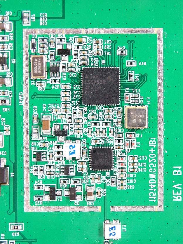
Click to zoom
Application Details
- Equipment Class
- DTS - Digital Transmission System
- Date of Grant
- Apr 17, 2005
- Application Purpose
- Original Equipment
- Date of Application
- Apr 17, 2005
- Equipment Note
- AIRPLUS TM G+802.11g/2.4GHz WIRELESS PCI ADAPTER
- Frequency Range
- 2412.00000000 - 2462.00000000
- Company
- D-Link Corporation
- Country
- United States
Documents & Files
Document Text
Text extracted from the exhibit documents filed with the FCC. Open a document above to read the original.
Users Manual
IEEE 802.11g PCI Adapter User’s Guide ii Regulatory notes and statements Wireless LAN, Health and Authorization for use Radio frequency electromagnetic energy is emitted from Wireless LAN devices. The energy levels of these emissions however are far much less than the electromagnetic energy emissions from wireless devices like for example mobile phones. Wireless LAN devices are safe for use frequency safety standards and recommendations. The use of Wireless LAN devices may be restricted in some situations or environments for example: ·On board of airplanes, or ·In an explosive environment, or ·In case the interference risk to other devices or services is perceived or identified as harmful In case the policy regarding the use of Wireless LAN devices in specific organizations or environments (e.g. airports, hospitals, chemical/oil/gas industrial plants, private buildings etc.) is not clear, please ask for authorization to use these devices prior to operating the equipment. Regulatory Information/disclaimers Installation and use of this Wireless LAN device must be in strict accordance with the instructions included in the user documentation provided with the product. Any changes or modifications made to this device that are not expressly approved by the manufacturer may void the user’s authority to operate the equipment. The Manufacturer is not responsible for any radio or television interference caused by unauthorized modification of this device, of the substitution or attachment. Manufacturer and its authorized resellers or distributors will assume no liability for any damage or violation of government regulations arising from failing to comply with these guidelines. iii USA-FCC (Federal Communications Commission) statement This device complies with Part 15 of FCC Rules. Operation is subject to the following two conditions: 1. This device may not cause interference, and 2. This device must accept any interference, including interference that may cause undesired operation of this device. FCC Radio Frequency Exposure statement This Wireless LAN radio device has been evaluated under FCC Bulletin OET 65 and found compliant to the requirements as set forth in CFR 47 Sections 2.1091, 2.1093, and 15.247 (b) (4) addressing RF Exposure from radio frequency devices. The radiated output power of this Wireless LAN device is far below the FCC radio frequency exposure limits. Nevertheless, this device shall be used in such a manner that the potential for human contact during normal operation is minimized. When nearby persons has to be kept to ensure RF exposure compliance, in order to comply with RF exposure limits established in the ANSI C95.1 standards, the distance between the antennas and the user should not be less than 20 cm. FCC Interference Statement This equipment has been tested and found to comply with the limits for a Class B digital device, pursuant to Part 15 of the FCC Rules. These limits are designed to provide reasonable protection against harmful interference in a residential installation. This equipment generates, uses, and can radiate radio frequency energy. If not installed and used in accordance with the instructions, it may cause harmful interference to radio communications. However, there is no guarantee that interference will not occur in a particular installation. If this equipment does cause harmful interference to radio or television reception, which can be determined by turning the equipment off and on, the user is encouraged to try and correct the interference by one or more of the following measures: iv 1. Reorient or relocate the receiving antenna. 2. Increase the distance between the equipment and the receiver. 3. Connect the equipment to an outlet on a circuit different from that to which the receiver is connected. 4. Consult the dealer or an experienced radio/TV technician for help. Export restrictions This product or software contains encryption code that may not be exported or transferred from the US of Canada without an approved US Department of Commerce export license. Safety Information Your device contains a low power transmitter. When device is transmitted it sends out radio frequency (RF) signal. CAUTION: To maintain compliance with FCC’s RF exposure guidelines, this equipment should be installed and operated with minimum distance 20cm between the radiator and your body. Use on the supplied antenna. Unauthorized antenna, modification, or attachments could damage the transmitter and may violate FCC regulations. CE Mark Warning This is a Class B product. In a domestic environment, this product may cause radio interference, in which case the user may be required to take adequate measures. v TABLE OF CONTENT Introduction.......................................................................................... 1 Overview of this User’s Guide......................................................... 1 Unpacking and Setup........................................................................... 3 Unpacking ........................................................................................ 3 Setup................................................................................................ 3 Hardware Installation........................................................................... 5 LED Indicator.................................................................................. 5 Check the installation....................................................................... 5 Software Installation ............................................................................ 7 Windows 98/ME/2000/XP Utility and Driver Installation............... 7 Wireless Utility Setting.................................................................... 8 Appendix A........................................................................................ 19 Regulatory Domains...................................................................... 19 1 INTRODUCTION Congratulations…
Text truncated - open the document above for the full version.
Cover Letter(s)
Address: 2F, NO. 232, Pao-Chiao Road, Hsin-Tien, Taipei, Taiwan, R.O.C. TEL: 886-2-2916-1600 FAX: 886-2-2914-6299 Request for Confidentiality Federal Communications Commission Authorization and Evaluation Division Subject: Confidentiality Request regarding application for certification of FCC ID: KA2DWLG520PLUSB1 Dear Madam or Sir: Pursuant to Sections 0.457 and 0.459 of the Commission’s Rules, we hereby request confidential treatment of information accompanying this application as outlined below: l Schematics l Part List l Block diagram l Operational description The above materials contain trade secrets and proprietary information not customarily released to the public. The public disclosure of these materials may be harmful to the applicant and provide unjustified benefits to its competitors. The applicant understands that pursuant to Section 0.457 of the Rules, disclosure of this application and all accompanying documentation will not be made before the date of the Grant for this application. Address: 2F, NO. 232, Pao-Chiao Road, Hsin-Tien, Taipei, Taiwan, R.O.C. TEL: 886-2-2916-1600 FAX: 886-2-2914-6299 Pursuant to DA 04-1705 June 15, 2004 of the Commission’s public notice, we also request temporary confidential treatment of information accompanying this application as outlined below: l External Photos l Internal Photos l Test Setup Photos l User’s Manual Sincerely, J.C. Liao, President D-Link Corp.
External Photos
External Photos of 802.11g / 2.4GHz Wireless PCI Adapter----------------------1/5 Applicant: D-Link Corporation FCC ID: KA2DWLG520PLUSB1 Training Research Co., Ltd., TEL: 886-2-26935155, Fax: 886-2-26934440 External Photos of 802.11g / 2.4GHz Wireless PCI Adapter----------------------2/5 Applicant: D-Link Corporation FCC ID: KA2DWLG520PLUSB1 Training Research Co., Ltd., TEL: 886-2-26935155, Fax: 886-2-26934440 External Photos of 802.11g / 2.4GHz Wireless PCI Adapter----------------------3/5 Applicant: D-Link Corporation FCC ID: KA2DWLG520PLUSB1 Training Research Co., Ltd., TEL: 886-2-26935155, Fax: 886-2-26934440 External Photos of 802.11g / 2.4GHz Wireless PCI Adapter----------------------4/5 Applicant: D-Link Corporation FCC ID: KA2DWLG520PLUSB1 Training Research Co., Ltd., TEL: 886-2-26935155, Fax: 886-2-26934440 External Photos of 802.11g / 2.4GHz Wireless PCI Adapter----------------------5/5 Applicant: D-Link Corporation FCC ID: KA2DWLG520PLUSB1 Training Research Co., Ltd., TEL: 886-2-26935155, Fax: 886-2-26934440
ID Label/Location Info
LABEL Sample and Location information -------------------------------------------------- 1/2 Applicant: D-Link Corporation FCC ID: KA2DWLG520PLUSB1 Training Research Co., Ltd., TEL: 886-2-26935155, Fax: 886-2-26934440 LABEL Position: LABEL Sample and Location information -------------------------------------------------- 2/2 Applicant: D-Link Corporation FCC ID: KA2DWLG520PLUSB1 Training Research Co., Ltd., TEL: 886-2-26935155, Fax: 886-2-26934440 LABEL Position:
Internal Photos
External Photos of 802.11g / 2.4GHz Wireless PCI Adapter----------------------1/5 Applicant: D-Link Corporation FCC ID: KA2DWLG520PLUSB1 Training Research Co., Ltd., TEL: 886-2-26935155, Fax: 886-2-26934440 External Photos of 802.11g / 2.4GHz Wireless PCI Adapter----------------------2/5 Applicant: D-Link Corporation FCC ID: KA2DWLG520PLUSB1 Training Research Co., Ltd., TEL: 886-2-26935155, Fax: 886-2-26934440 External Photos of 802.11g / 2.4GHz Wireless PCI Adapter----------------------3/5 Applicant: D-Link Corporation FCC ID: KA2DWLG520PLUSB1 Training Research Co., Ltd., TEL: 886-2-26935155, Fax: 886-2-26934440 External Photos of 802.11g / 2.4GHz Wireless PCI Adapter----------------------4/5 Applicant: D-Link Corporation FCC ID: KA2DWLG520PLUSB1 Training Research Co., Ltd., TEL: 886-2-26935155, Fax: 886-2-26934440 External Photos of 802.11g / 2.4GHz Wireless PCI Adapter----------------------5/5 Applicant: D-Link Corporation FCC ID: KA2DWLG520PLUSB1 Training Research Co., Ltd., TEL: 886-2-26935155, Fax: 886-2-26934440
RF Exposure Info
Measurement of Maximum Permissible Exposure ----------------------------------------- 1/3 Applicant: D-Link Corporation FCC ID: KA2DWLG520PLUSB1 Training Research Co., Ltd., TEL: 886-2-26935155, Fax: 886-2-26934440 Measurement of Maximum Permissible Exposure 1. Foreword In adopt with the Human Exposure IEEE C95.1, and according to the FCC 1.1310. The Maximum Permissible Exposure (MPE) is obligated to measure in order to prove the safety of radiation harmfulness to the human body. The Gain of the antenna used is measured in an Anechoic chamber. The maximum total power to the antenna is to be recorded. By adopting the Friis Transmission Formula and the power gain of the antenna, we can find the distance right away from the product, where the limit of the MPE is. 2. Description of EUT FCC ID : KA2DWLG520PLUSB1 Product name : AirPlus TM G+ 802.11g/2.4GHz Wireless PCI Adapter Model name : DWL-G520+ Classification : Mobile Device (i) Under normal use condition, the antenna is at least 20cm away from the user; (ii) Warning statement for keeping 20cm separation distance and the prohibition of operating next to the person has been printed in the user’s manual Frequency Range : 2.412 GHz ~ 2.462GHz Supported Channel : 11 Channels Modulation Skill : DBPSK, DQPSK, CCK, OFDM Power Type : Powered by PCI of client’s device Measurement of Maximum Permissible Exposure ----------------------------------------- 2/3 Applicant: D-Link Corporation FCC ID: KA2DWLG520PLUSB1 Training Research Co., Ltd., TEL: 886-2-26935155, Fax: 886-2-26934440 3. Limits for Maximum Permissible Exposure (MPE) Frequency Range (MHz) Electric Field Strength (V/m) Magnetic Filed Strength (H) (A/m) Power Density (S) (mW/cm2) Averaging Time |E| 2 , |H| 2 or S (minutes) (A) Limits for Occupational/Controlled Exposure 0.3-3.0 614 1.63 100 6 3.0-30 1842/f 4.89/f 900/f 2 6 30-300 61.4 0.163 1.0 6 300-1500 -- -- f/300 6 1500-100,000 -- -- 5 6 (B) Limits for General Population/Uncontrolled Exposure 0.3-1.34 614 1.63 100 30 1.34-30 824/f 2.19/f 180/f 2 30 30-300 27.5 0.073 0.2 30 300-1500 -- -- f/1500 30 1500-100,000 -- -- 1.0 30 [The EUT is tested in transmit and receive modes and in the first, middle and the last channel separately. The following shows only our observation have the greatest emissions.] According to OET BULLETIN 56 Fourth Edition/August 1999, Equation for Predicting RF Fields: Friis Transmission Formula: 2 22 /04976.0 )20(4 514.1196.165 4 cmmW R PG S= × == ππ Estimated safe separation: cm xPG R46126.4 4 514.1196.165 4 === ππ Remarks: "The safe estimated separation that the user must maintain from the antenna is at least 4.46 cm." Where: S = power density (in appropriate units, e.g. mW/cm2) P = power input to the antenna (in appropriate units, e.g., mW) G = power gain of the antenna in the direction of interest relative to an isotropic radiator R = distance to the center of radiation of the antenna (appropriate units, e.g., cm) The Numeric gain G of antenna with a gain specified in dB is determined by: G = Log -1 ( dB antenna gain / 10 ) G = Log -1 (1.80 / 10) = 1.51356 Measurement of Maximum Permissible Exposure ----------------------------------------- 3/3 Applicant: D-Link Corporation FCC ID: KA2DWLG520PLUSB1 Training Research Co., Ltd., TEL: 886-2-26935155, Fax: 886-2-26934440 Appendix Antenna Specification
Test Report
Test Report -------------------------------------------------------------------------------1/53 Report No.: D1815050188, FCC Part 15.247 Training Research Co., Ltd., TEL: 886-2-26935155, Fax: 886-2-26934440 MEASUREMENT REPORT of Wireless PCI Adapter Applicant:D-Link Corporation EUT:AirPlus TM G+ 802.11g/2.4GHz Wireless PCI Adapter Model:DWL-G520+ FCC ID:KA2DWLG520PLUSB1 Tested by : Training Research Co., Ltd. TEL : 886-2-26935155 FAX : 886-2-26934440 No. 255, Nanyang Street, Shijr, Taipei Hsien 221, Taiwan, R.O.C. Test Report -------------------------------------------------------------------------------2/53 Report No.: D1815050188, FCC Part 15.247 Training Research Co., Ltd., TEL: 886-2-26935155, Fax: 886-2-26934440 CERTIFICATION We here by verify that: The test data, data evaluation, test procedures and equipment configurations shown in this report were made mainly in accordance with the procedures given in ANSI C63.4 (2003) as a reference. All test were conducted by Training Research Co., Ltd., 255 Nanyang Street, Shijr, Taipei Hsien 221, Taiwan, R.O.C. Also, we attest to the accuracy of each. We further submit that the energy emitted by the sample EUT tested as described in the report is in compliance with the technical requirements set forth in the FCC Rules Part 15 Subpart B (Declaration of Conformity) and Subpart C Section 15.247. Applicant:D- Link Corporation Applicant address:2F, No. 233-2, Pao-Chiao Rd., Hsin-Tien, Taipei, Taiwan Product Name:AirPlus TM G+ 802.11g/2.4GHz Wireless PCI Adapter Model Name:DWL-G520+ Report No.:D1815050188 Test Date:April14, 2005 Prepared by:Approved by: Jack TsaiFrank Tsai Conditions of issue : (1) This test report shall not be reproduced except in full, without written approval of TRC. And the test result contained within this report only relate to the sample submitted for testing. (2) This report must not be used by the client to claim product endorsement by NVLAP or any agency of U.S. Government. (3) This test report, measurements made by TRC are traceable to the NIST only Conducted and Radiated Method. NVLAP LAB CODE: 200174-0 Test Report -------------------------------------------------------------------------------3/53 Report No.: D1815050188, FCC Part 15.247 Training Research Co., Ltd., TEL: 886-2-26935155, Fax: 886-2-26934440 Federal Communications Commission Declaration of Conformity for the following equipment: Product name:AirPlus TM G+ 802.11g/2.4GHz Wireless PCI Adapter Trade name:D-Link Model name:DWL-G520+ Is herewith confirmed and found to comply with the requirements of CFR 47 part15 Subpart B - Unintentional Radiators regulation. The results of electromagnetic mission evaluation are shown in the report number : D1815050188 This device complies with Part 15 of the FCC Rules. Operation is subject to the following two conditions: (1) This device may not cause harmful interference, and (2) This device must accept any interference received, including interference that may cause undesired operation Manufacturer USA local representative Company name: D-Link CorporationTo be determined Computer address: 2F, No. 233-2, Pao-Chiao Rd., Hsin-Tien, Taipei, Taiwan ZIP / Postal code 231 Contact person: J.C.Liao Title: President Internet e -mail address: [email protected] Tel / Fax: 886-2-29161600 / 886-2-29146299 Test Report -------------------------------------------------------------------------------4/53 Report No.: D1815050188, FCC Part 15.247 Training Research Co., Ltd., TEL: 886-2-26935155, Fax: 886-2-26934440 Tables of Contents I.GENERAL................................................................................................................... 6 1.1Introduction........................................................................................................... 6 1.2Description of EUT ................................................................................................ 6 1.3Test method .......................................................................................................... 6 1.4Description of Support Equipment .......................................................................... 7 1.5Configuration of System Under Test...................................................................... 10 1.6Verify the Frequency and Channel ......................................................................... 12 1.7Test Procedure..................................................................................................... 13 1.8Location of the Test Site ....................................................................................... 13 1.9General Test Condition ......................................................................................... 13 II.Section 15.101(a) : Equipment Authorization of Unintentional Radiators................. 14 III. Section 15.203 : Antenna Requirement....................................................................... 15 IV.Section 15.207 : Power Line Conducted Emissions for AC Powered Units............. 16 4.1Test Condition & Setup........................................................................................ 16 4.2List of Test Instruments ......................................................................................... 17 4.3Test Result of Conducted Emissions ...................................................................... 18 RX mode ............................................................................................................... 18 IEEE 802.11b ......................................................................................................... 19 IEEE 802.11g ......................................................................................................... 21 V.Section 15.247(a) : Technical Description of the EUT................................................ 22 VI.Section 15.247(a)(2) : Bandwidth for Direct Sequence System................................ 23 6.1Test Condition & Setup...............…
Text truncated - open the document above for the full version.
Test Setup Photos
Test Setup Photos ------------------------------------------------------------------------ 1/2 Applicant: D-Link Corporation FCC ID: KA2DWLG520PLUSB1 Training Research Co., Ltd., TEL: 886-2-26935155, Fax: 886-2-26934440 Conducted Test Setup Placement: Front View of the Test Configuration Side View of the Test Configuration Test Setup Photos ------------------------------------------------------------------------ 2/2 Applicant: D-Link Corporation FCC ID: KA2DWLG520PLUSB1 Training Research Co., Ltd., TEL: 886-2-26935155, Fax: 886-2-26934440 Radiated Test Setup Placement: Front View of the Test Configuration Rear View of the Test Configuration
Contact Information
Applicant
Brett Adair(General Counsel)
Test Firm
Training Research Co., LtdJack Tsai
Technical Specifications
| # | Rule Parts | Frequency Range | Power Output |
|---|---|---|---|
| 1 | 15C | 2.41 GHz - 2.46 GHz | 165.00 mW |
Other Applications from D-Link Corporation

KA2CS6012A1
Jul 07, 20262K Fixed Indoor Cloud Camera, 2K Fixed Indoor Wi-Fi Camera
Equipment Class
DTS - Digital Transmission SystemKA2AE65UA1
Mar 02, 2026Wi-Fi 7 BE6500 USB 3.0 Dongle
Equipment Class
NII - Unlicensed National Information Infrastructure TXKA2APE9560A1
Nov 17, 2025BE9500 Celling mount Access Point
Equipment Class
6ID - 15E 6 GHz Low Power Indoor Access PointKA2AX9UA1
Dec 04, 2024AX900 Wi-Fi 6 USB Adapter, Wi-Fi 6 AX900 USB 2.0 Dongle
Equipment Class
DSS - Part 15 Spread Spectrum TransmitterKA2AC13UA1
Dec 04, 2024AC1300 Wi-Fi 5 USB Adapter, Wi-Fi 5 AC1300 USB 2.0 Dongle
Equipment Class
DTS - Digital Transmission System