KA2DWLG810802.11g High-Speed Ethernet-to-Wireless Bridge
D-Link Corporation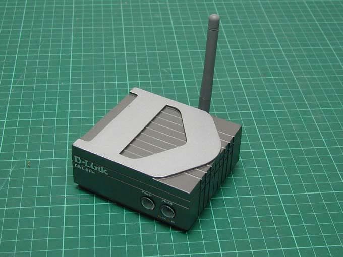
Click to zoom
Application Details
- Equipment Class
- DTS - Digital Transmission System
- Date of Grant
- Nov 04, 2003
- Application Purpose
- Original Equipment
- Date of Application
- Nov 04, 2003
- Equipment Note
- 802.11g High-Speed Ethernet-to-Wireless Bridge
- Frequency Range
- 2412.00000000 - 2462.00000000
- Company
- D-Link Corporation
- Country
- United States
Documents & Files
Document Text
Text extracted from the exhibit documents filed with the FCC. Open a document above to read the original.
Users Manual
Building Networks for People DWL-G810 D-Link AirPlus XtremeG 802.11g High-Speed Ethernet-to-Wireless Bridge Manual 2 Contents 1. Package Contents ............................... 3 2. Introduction......................................... 4 3. Wireless Basics................................... 7 4. Getting Started ................................. 10 5. Web Configuration ............................. 12 6. Troubleshooting ................................ 18 8. Technical Specifications................... 25 9. Contacting Technical Support .......... 28 10. Warranty and Registration ............... 29 3 1. Package Contents Contents of Package: • D-Link AirPlus XtremeG DWL-G810 Ethernet-to-Wireless Bridge • AC Power Adapter – 5V; 2.5A • Manual and Warranty on CD • Ethernet Cable (the DWL-G810 Auto MDI/MDIX Ethernet port works with straight-through or crossover cable) • Quick Installation Guide If any of the above items are missing, please contact your reseller. System Requirements for Configuration: • A computer with an Ethernet adapter. (We recommend that you use an Ethernet connection to configure the DWL-G810.) • A current web-browser (e.g., Internet Explorer 6.0 or Netscape Navigator 6.0 or later) for configuration For Use: You will need an Ethernet-enabled device such as a game console, laptop or desktop computer, network printer or set top box. The DWL-G810 will transform virtually any Ethernet device into a wireless device, enabling wireless communication over your network or in an ad-hoc/peer-to- peer mode. 4 2. Introduction The D-Link AirPlus XtremeG DWL-G810 Ethernet-to-Wireless Bridge is a device that can be implemented in a variety of ways to provide wireless access by converting an Ethernet connection. For devices with a built-in Ethernet port, the DWL-G810 provides a cost effective way to gain wireless connectivity, virtually transforming wired devices into wireless units! Connect any Ethernet-enabled device to 802.11g wireless network and legacy 802.11g wireless network using the DWL-G810. Typical applications include connecting a printer to a wireless network and connecting Ethernet-enabled devices such as game consoles or set top boxes to a Wireless Local Area Network (WLAN). Simply connect the DWL- G810 to the Ethernet (RJ-45) port of a network device, such as a network storage device, Internet camera, network printer, network scanner, or other similar device. Using the DWL-G810 allows the flexibility of placing network devices in remote locations while maintaining a high-speed connection. You can use the convenient Setup Wizard for the easy installation of your DWL-G810. Whether you are using it in Ad-Hoc mode or Infrastructure mode, you can begin with the Setup Wizard. Please refer to the Quick Installation Guide that is included with your purchase for instructions on how to use the Setup Wizard. This manual provides a quick introduction to wireless technology and its application as it relates to networking. Please take a moment to read through this manual if you need to get acquainted with wireless technology. 5 Features and Benefits • Transforms an Ethernet device into a wireless device • Up to 54Mbps transfer rates* • Fully compatible with standard 802.11g/b-compliant devices • Equipped with one 10/100 Ethernet port, Auto-MDI/MDIX • Quick and Simple connectivity via Ethernet • Supports Ad Hoc or Infrastructure modes • Easy web-based configuration when changing settings • Encryption to provide a level of security for data transfers LEDs LED stands for Light-Emitting Diode. The DWL-G810 has two LEDs: Power – a steady Green light indicates a proper connection to a power source. Wireless Link/Act – A blinking light indicates that the DWL-G810 is receiving/transmitting from/to the wireless network. 6 Connections Reset Button – press this button to revert to the factory default settings of the DWL-G810 Power Receptor – connect one end of the 5V DC Power Adapter (included) to the power receptor on the DWL-G810 and connect the other end of the Power Adapter to a power outlet. Default Settings Operating Mode Infrastructure SSID default Channel 6 Transmission rates Auto Encryption Disabled IP Address 192.168.0.30 IP Subnet 255.255.255.0 User Name admin (all lower case) Password None (leave field blank) Ethernet Port Reset Button Power Receptor Category 5 is the most reliable grade of twisted-pair cable. It is available as either Straight-Through cable or Cross-Over cable. Always check your installation instructions to make sure that you have selected the correct type of Category 5 cable for your other networking devices. The DWL-G810 will accept either kind of cable and will automatically sense the cable that you are using. Ethernet Port – this RJ-45 Auto MDI/MDIX port provides connection to a network device using a Cat 5 Ethernet cable. (The auto MDI/MDIX port accommodates either Straight- Through or Cross-Over cable and is auto-sensing.) 7 3. Wireless Basics With the DWL-G810 you can provide instant wireless access to the LAN (Local Area Network) for Ethernet-enabled devices. With an Ethernet (CAT5) cable simply connect the DWL-G810 to the Ethernet port of a network device (such as a printer or web camera) to establish a wireless connection with another device equipped with a wireless network adapter set to Ad-Hoc mode. If you are planning a larger wireless network, D-Link offers a wide array of products for most of your wireless local area network (WLAN) needs. In this section, we discuss typical WLANs and their components. Much of the advice given here may be helpful in setting up the DWL-G810. It may also give you some ideas, if you plan to expand your wireless network. D-Link wireless products are based on industry standards to provide easy-to- use and compatible high-speed wireless connectivity within your home, business or wherever a wireless network is available. D-Link wireless products will allow you access to the data you want, when and where you want it. No longer wi…
Text truncated - open the document above for the full version.
External Photos
Photo 1: Exterior photo of EUT DWL-G810 Photo 2: Exterior photo of EUT DWL-G810
ID Label/Location Info
FCC ID Label Location 4 mm 4 mm
Internal Photos
Photo 1: Interior photo of EUT DWL-G810 Photo 2: Interior photo of EUT DWL-G810 Photo 3: Interior photo of EUT DWL-G810
RF Exposure Info
FCC ID. : KA2DWLG810 Report No.: EME-031119 Page 1 of 6 Maximum Permissible Exposure (MPE) Evaluation Report Report No. : EME-031119 Model No. : DWL-G810 Issued Date : Oct. 8, 2003 Applicant : D-Link Corporation 2F, No. 233-2, Pao-Chiao Road, Hsin-tien, Taipei, Taiwan Test By : Intertek Testing Services Taiwan Ltd. No. 11, Lane 275, Ko-Nan 1 Street, Chia-Tung Li, Shiang-Shan District, Hsinchu City, Taiwan This test report consists of 6 pages in total. It may be duplicated completely for legal use with the allowance of the applicant. It shall not be reproduced except in full, without the written approval of ITS Laboratory. The test result in this report only applies to the tested sample. Jerry Liu Project Engineer Reviewed By Elton Chen FCC ID. : KA2DWLG810 Report No.: EME-031119 Page 2 of 6 Table of Contents Summary of Tests.........................................................................................................3 1. Introduction..............................................................................................................4 2. RF Exposure Limit...................................................................................................4 3. RF Exposure calculations..........................................................................................5 4. Test results................................................................................................................5 FCC ID. : KA2DWLG810 Report No.: EME-031119 Page 3 of 6 Summary of Tests MPE Evaluation meet FCC OET No. 65: 1997/ IEEE C95.1-1999 802.11g High-speed Ethernet-to-Wireless Bridge -Model: DWL-G810 FCC ID: KA2DWLG810 Test Reference Results MPE Evaluation FCC Guidelines for Human Exposure IEEE C95.1 Complies FCC ID. : KA2DWLG810 Report No.: EME-031119 Page 4 of 6 1. Introduction The EUT operates in the 2.4GHz ISM band. Due to the EUT (include antenna) at its normal operation distance is at least 20 cm from the human body, the EUT was defined as a Mobile Device. The reason to do the MPE Evaluation is to avoid the RF hazard to human body. The maximum output power and gain of the antenna were used to calculate the limited Power density (S) at 20cm distance away from the product. The limit for Maximum Permissible Exposure (MPE) specified in FCC 1.1310 is followed. 2. RF Exposure Limit According to FCC 1.1310: The criteria listed in the following table shall be used to evaluate the environmental impact of human exposure to radio-frequency (RF) radiation as specified in 1.1307(b). Limits for Maximum Permissible Exposure (MPE) Frequency Range (MHz) Electric Field Strength (V/m) Magnetic Field Strength (A/m) Power Density (mW/cm 2 ) Average Time (minutes) (A) Limits for Occupational / Control Exposures 30-300 61.4 0.163 1.0 6 300-1500 - - F/300 6 1500-100,000 - - 5 6 (B) Limits for General Population / Uncontrolled Exposure 30-300 27.5 0.073 0.2 30 300-1500 - - F/1500 30 1500-100,000 - - 1.0 30 F= Frequency in MHz FCC ID. : KA2DWLG810 Report No.: EME-031119 Page 5 of 6 3. RF Exposure calculations From § FCC 1.1310 table 1, the maximum permissible RF exposure for an uncontrolled environment is 1mW/(cm 2 ) Power density (S) is calculated by the following formula: S = (P * G)/4πR 2 where, S = Power density (mW/cm 2 ) P = Output power to antenna (mW) R = Distance between radiating structure and observation point (cm) G = Gain of antenna in numeric π = 3.1416 Example: Assume a mobile device operates at 2412MHz and its maximum output power is 50mW, and the maximum gain of antenna is 1 (numeric) /0dBi. then the power density (S) = (50 * 1)/4* π *20 2 = 0.00995 (mW/cm 2 ) 4. Test results Test Condition: 802.11b operation (DSSS Modulation) Channel Channel Frequency (MHz) Maximum antenna gain (numeric) Output power to antenna (mW) Power density (mW/cm 2 ) Limit of power density (mW/cm 2 ) 1 2412 1.58 24.15 0.00761 1.0 6 2437 1.58 22.03 0.00695 1.0 11 2462 1.58 17.91 0.00565 1.0 The Notice in Installation Manual has been stated as below: While installing and operating this transmitter, the radio frequency exposure limit of 1mW/(cm*cm) may be exceeded at distances close to the transmitter. therefore, the user must maintain a minimum distance of 20 cm from the device at all time. FCC ID. : KA2DWLG810 Report No.: EME-031119 Page 6 of 6 Test Condition: 802.11g operation (OFDM Modulation) Channel Channel Frequency (MHz) Maximum antenna gain (numeric) Output power to antenna (mW) Power density (mW/cm 2 ) Limit of power density (mW/cm 2 ) 1 2412 1.58 31.12 0.00981 1.0 6 2437 1.58 28.38 0.00895 1.0 11 2462 1.58 30.41 0.00959 1.0 The Notice in Installation Manual has been stated as below: While installing and operating this transmitter, the radio frequency exposure limit of 1mW/(cm*cm) may be exceeded at distances close to the transmitter. therefore, the user must maintain a minimum distance of 20 cm from the device at all time.
Test Report
FCC ID. : KA2DWLG810 Report No.: EME-031119 Page 1 of 46 EMC TEST REPORT Report No. : EME-031119 Model No. : DWL-G810 Issued Date : Sep. 24, 2003 Applicant : D-Link Corporation 2F, No. 233-2, Pao-Chiao Road, Hsin-tien, Taipei, Taiwan Test By : Intertek Testing Services Taiwan Ltd. No. 11, Lane 275, Ko-Nan 1 Street, Chia-Tung Li, Shiang-Shan District, Hsinchu City, Taiwan This test report consists of 46 pages in total. It may be duplicated completely for legal use with the allowance of the applicant. It shall not be reproduced except in full, without the written approval of Intertek Laboratory. The test result in this report only applies to the tested sample. Jerry Liu Project Engineer Reviewed By Elton Chen FCC ID. : KA2DWLG810 Report No.: EME-031119 Page 2 of 46 Table of Contents Summary of Tests..........................................................................................................3 1. General information..................................................................................................4 1.1 Identification of the EUT....................................................................................4 1.2 Additional information about the EUT................................................................4 1.3 Antenna description............................................................................................5 1.4 Peripherals equipment.........................................................................................5 2. Test specifications.....................................................................................................6 2.1 Test standard.......................................................................................................6 2.2 Operation mode..................................................................................................6 2.3 Test equipment....................................................................................................7 3. Minimum 6dB Bandwidth test...................................................................................8 3.1 Operating environment.......................................................................................8 3.2 Test setup & procedure........................................................................................8 3.3 Measured data of Minimum 6dB Bandwidth test results......................................8 4. Maximum Output Power test...................................................................................15 4.1 Operating environment.....................................................................................15 4.2 Test setup & procedure......................................................................................15 4.3 Measured data of Maximum Output Power test results......................................15 5. Radiated Emission test............................................................................................17 5.1 Operating environment.....................................................................................17 5.2 Test setup & procedure......................................................................................17 5.3 Emission limits.................................................................................................18 5.4 Radiated spurious emission test data.................................................................19 5.4.1 Measurement results: frequencies equal to or less than 1 GHz........................19 5.4.2 Measurement results: frequency above 1GHz.................................................21 6. Power Spectrum Density test...................................................................................22 6.1 Operating environment.....................................................................................22 6.2 Test setup & procedure......................................................................................22 6.3 Measured data of Power Spectrum Density test results......................................22 7. Emission on the band edge §FCC 15.247(C)...........................................................29 7.1 Band-edge (Conducted method)........................................................................30 7.2 Band-edge (Radiated method)...........................................................................34 8. Power Line Conducted Emission test §FCC 15.207.................................................42 8.1 Operating environment.....................................................................................42 8.2 Test setup & procedure......................................................................................42 8.3 Power Line Conducted Emission test data.........................................................44 FCC ID. : KA2DWLG810 Report No.: EME-031119 Page 3 of 46 Summary of Tests 802.11g High-speed Ethernet-to-Wireless Bridge-Model: DWL-G810 FCC ID: KA2DWLG810 Test Reference Results Minimum 6dB Bandwidth test 15.247(a)(2) Complies Maximum Output Power test 15.247(b) Complies Radiated Spurious Emission test 15.205, 15.209 Complies Power Spectrum Density test 15.247(d) Complies Power Line Conducted Emission test 15.207 Complies FCC ID. : KA2DWLG810 Report No.: EME-031119 Page 4 of 46 1. General information 1.1 Identification of the EUT Applicant : D-Link Corporation Product : 802.11g High-speed Ethernet-to-Wireless Bridge Model No. : DWL-G810 FCC ID. : KA2DWLG810 Frequency Range : 2412~2462MHz Channel Number : 11 channels Frequency of Each Channel : 2412MHz, 2417MHz, 2422MHz, 2427MHz, 2432MHz, 2437MHz, 2442MHz, 2447MHz, 2452MHz, 2457MHz, 2462MHz Type of Modulation : DSSS, OFDM Rated Power : 120Vac, 60Hz Power Cord : N/A Sample Received : Sep. 9, 2003 Test Date(s) : Sep. 9, 2003 ~ Oct. 2, 2003 A FCC DoC report has been generated for the client. 1.2 Additional information about the EUT The D-Link AirPlus XtremeG DWL-G810 Ethernet-to-Wireless Bridge is a device that can be im…
Text truncated - open the document above for the full version.
Test Setup Photos
Photo 1: Conducted Emission Test Set-up Photo 2: Conducted Emission Test Set-up Photo 3: Conducted Emission Test Set-up
Test Setup Photos
Photo 1: Radiated Emission Test Set-up Photo 2: Radiated Emission Test Set-up Photo 3: Radiated Emission Test Set-up
Contact Information
Applicant
Brett Adair(General Counsel)
Technical Contact
Intertek Testing Services Taiwan Ltd.Elton Chen
[email protected]+886 3 519 1411
11, Ln 275, KoNam 1st St, Shiang-Shan District · Hsinchu · Taiwan
Test Firm
Intertek Testing Services Taiwan Ltd.Alpha Liu
Technical Specifications
| # | Rule Parts | Frequency Range | Power Output |
|---|---|---|---|
| 1 | 15C | 2.41 GHz - 2.46 GHz | 31.00 mW |
Other Applications from D-Link Corporation

KA2CS6012A1
Jul 07, 20262K Fixed Indoor Cloud Camera, 2K Fixed Indoor Wi-Fi Camera
Equipment Class
DTS - Digital Transmission SystemKA2AE65UA1
Mar 02, 2026Wi-Fi 7 BE6500 USB 3.0 Dongle
Equipment Class
NII - Unlicensed National Information Infrastructure TXKA2APE9560A1
Nov 17, 2025BE9500 Celling mount Access Point
Equipment Class
6ID - 15E 6 GHz Low Power Indoor Access PointKA2AX9UA1
Dec 04, 2024AX900 Wi-Fi 6 USB Adapter, Wi-Fi 6 AX900 USB 2.0 Dongle
Equipment Class
DSS - Part 15 Spread Spectrum TransmitterKA2AC13UA1
Dec 04, 2024AC1300 Wi-Fi 5 USB Adapter, Wi-Fi 5 AC1300 USB 2.0 Dongle
Equipment Class
DTS - Digital Transmission System