KA2DWM162RUSB Modem
D-Link Corporation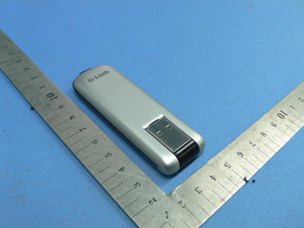
Click to zoom
Application Details
- Equipment Class
- JBP - Part 15 Class B Computing Device Peripheral
- Date of Grant
- Apr 28, 2010
- Application Purpose
- Original Equipment
- Date of Application
- Apr 28, 2010
- Equipment Note
- USB Modem
- Company
- D-Link Corporation
- Country
- United States
Documents & Files
Document Text
Text extracted from the exhibit documents filed with the FCC. Open a document above to read the original.
Users Manual
2D-Link DWM-162R User Manual Table of Contents DWM-162R User Manual 1. INTRODUCTION ..........................................................1 2. FEATURES ..................................................................1 3. PRODUCT OVERVIEW ...............................................1 3.1 PACKING CONTENT ...........................................1 3.2 SYSTEM REQUIREMENTS ................................1 3.3 HARDWARE OVERVIEW ...................................2 3.4 LED INDICATOR INFORMATION .......................3 3.5 UIM CARD INSTALLATION.................................3 3.6 MICROSD CARD INSTALLATION ......................3 3.7 SOFTWARE INSTALLATION ..............................4 4. BASIC FUNCTION .......................................................5 4.1 LAUNCHING THE CONNECTION MANAGER .. 5 4.2 CONNECTION MANAGER OVERVIEW ............6 4.3 DATA LINK ...........................................................6 4.3.1 To Make the Data Link ...................................6 4.3.2 To set up a profile ...........................................7 4.4 VOICE CALL ........................................................7 4.4.1 To Make a Voice Call .....................................8 4.4.2 To Receive a Voice Call .................................8 4.5 SMS ......................................................................8 4.5.1 To Send a SMS ..............................................9 4.5.2 To receive a SMS ...........................................9 4.6 CONTACTS ........................................................10 4.7 CALL HISTORY .................................................10 5. TROUBLESHOOTING ...............................................10 1D-Link DWM-162R User Manual Section 1 - Product Overview 1. Introduction DWM-162R is a CDMA EVDO Rev.A USB dongle. Besides Windows OS, DWM-162R can also be run under MAC environment which makes it become the perfect solution for customization. DWM-162R can support the downlink up to 3.1 Mbps and uplink up to 1.8Mbps. 2. Features Compact and sleek dongle easily fits in your pocket Provides EVDO/CDMA network support Plug-and-Play: No CD-ROM required Connection software launches quickly and automatically Convenient USB connector requires no additional cables MicroSD card reader slot for optional removable storage 3. Product Overview 3.1 Packing Content D-Link DWM-162R ---CDMA EVDO Rev.A Dongle 3.2 System Requirements We recommend that your PC should be: Windows 2000 SP4, Windows XP SP2, Windows Vista, Windows 7 or Mac OS 10.4+ Standard USB 2.0 interface Screen Resolution: 800 by 600 pixels The hardware should satisfied with the OS requirements If your PC do not satisfied with the commended configuration, the USB modem would be possible does not work properly. 2D-Link DWM-162R User Manual Section 1 - Product Overview UIM Card Slot Accepts a UIM card (up to 8GB). MicroSD Card Slot Accepts a MicroSD card (up to 8GB). 3.3 Hardware Overview USB Port Connects the DWM-162R to a computer. Status Indicator A multi-colored LED indicates connection status information. 3D-Link DWM-162R User Manual Table of Contents 3.5 UIM Card Installation 1. Ensure the USB modem is plug off. Remove the back cover. 2. Hold the UIM card with the cut corner oriented as shown and then slide it into the card holder face down. 3. Replace the back cover. 3.6 MicroSD Card Installation 1. Ensure the USB modem is plug off. Remove the back cover. 2. Hold the MicroSD card with the oriented as shown and then slide it into the card holder face up. 3. Replace the back cover. LED IndicationsDongle Working Status Long BurningSystem initializing On 0.2s, Off 1.9s, RepeatNo Signal / Searching On 0.2s, Off 0.2s, On 0.2s, Off 1.7s RepeatIdle with Signal On 0.2s, Off 0.2s, RepeatIn used 3.4 LED Indicator Information 4D-Link DWM-162R User Manual Section 1 - Product Overview 2. Please follow the installation by clicking “Next”, the application will install the driver and the connection manager to your computer automatically 3.7 Software Installation Before you install the software, you must first install a UIM card into the USB dongle and connect the dongle to a USB port on your computer. 1. The first time you plug in the dongle to your computer, the dongle will run the installation application automatically. 5D-Link DWM-162R User Manual Section 2 - Installation 4 Basic Function 4.1 Launching the Connection Manager To Launch the Connection Manager, double-click the shortcut icon of the Connection Manager on the desktop called D-Link Mobile ConnMgr. . 4. Now you could use your dongle to go to the internet. 3. Please click “Finish” to finish the installation. Then plug out the dongle and reinsert the dongle to PC. The connection manager will pop up automatically. 6D-Link DWM-162R User Manual Section 2 - Installation 4.3.1 To Make the Data Link Before making the data link, you need to setting the network and connection profiles; you can access the network through the Connection Manager. You can connect the network as below: a. Click , b. Select the correct profile in the drop-down list, c. Click Connect to connect the network, d. After connection established, you could access the internet. e. To disconnect, Click Disconnect. 4.3 Data Link You can establish a dialup data link over CDMA EVDO/CDMA 1x via the dongle. The dialup data link requires the coverage of CDMA network. 4.2 Connection Manager Overview The main menu of the Connection Manager is as below: Icons: Display the Connection Interface. Display the Voice Call Interface. Display the SMS Interface Display the Contacts Interface Display the Call History Interface. Indicate the network signal strength. 7D-Link DWM-162R User Manual Section 2 - Installation 4.4 Voice Call Once you connect to the network, you could make and receive the voice all. Click on the icon to enter the voice call interface. Make sure you have sound card in your PC, and you have speaker and microphone connected on the PC. 4.3.2 To set up a prof…
Text truncated - open the document above for the full version.
External Photos
PHOTOGRAPH OF THE EUT 1. Appearance of the EUT
Internal Photos
PHOTOGRAPH OF THE EUT 1. inside of the EUT
Test Report
Report No.: SH10030026E01 Page 2 of 15 TABLE OF CONTENTS 1. TEST CERTIFICATION ........................................................................................................... 3 2. GENERAL INFORMATION .................................................................................................... 4 2.1 EUT Description ......................................................................................................................... 4 2.2 Test Standards and Results ........................................................................................................ 5 2.3 Facilities and Accreditations ...................................................................................................... 6 2.3.1 Facilities .................................................................................................................................... 6 2.3.2 Test Environment Conditions .................................................................................................... 6 3. TEST CONDITIONS SETTING .............................................................................................. 7 3.1 CDMA Test Mode ....................................................................................................................... 7 3.2 Test Setup and Equipments List ................................................................................................ 8 3.2.1 Conducted Emission ................................................................................................................. 8 3.2.2 Radiated Emission ..................................................................................................................... 9 4. 47 CFR Part 15B Requirements .............................................................................................. 10 4.1 Conducted Emission ................................................................................................................. 10 4.1.1 Requirement ............................................................................................................................ 10 4.1.2 Test Description ...................................................................................................................... 10 4.1.3 Test Result ............................................................................................................................... 10 4.2 Radiated Emission .................................................................................................................... 13 4.2.1 Requirement ............................................................................................................................ 13 4.2.2 Test Description ...................................................................................................................... 13 4.2.3 Test Result ............................................................................................................................... 14 Report No.: SH10030026E01 Page 4 of 15 2. GENERAL INFORMATION 2.1 EUT Description EUT Type.............................. : USB MODEM Model Name ......................... : DWM-162R Serial No. .............................. : (n.a., marked #1 by test site) Hardware Version ................. : 325-0091-001-2 Software Version .................. : V1.0.3.6 Modulation Type ................... : QPSK Ancillary Equipment .......... : 1: Notebook PC Model Name: THINKPAD R40e Brand Name: IBM Note 1: A communication link between the EUT and a System Simulator (SS) is established at the start of the test, and maintained during the all test in this report. Note 2: For a more detailed description, please refer to Specification or User’s Manual supplied by the applicant and/or manufacturer. Report No.: SH10030026E01 Page 5 of 15 2.2 Test Standards and Results The objective of the report is to perform testing according to 47 CFR Part 15 Subpart B: No. Identity Document Title 1 47 CFR Part 15 (10-1-05 Edition) Radio Frequency Devices Test detailed items/section required by FCC rules and results are as below: No. Section Description Result 1 15.107 Conducted Emission PASS 2 15.109 Radiated Emission PASS Report No.: SH10030026E01 Page 6 of 15 2.3 Facilities and Accreditations 2.3.1 Facilities Shenzhen Electronic Product Quality Testing Center Morlab Laboratory is a testing organization accredited by China National Accreditation Service for Laboratories (CNAS) according to ISO/IEC 17025. The accreditation certificate number is L1659. All measurement facilities used to collect the measurement data are located at Electronic Testing Building, Shahe Road, Xili, Nanshan District, Shenzhen 518055 CHINA. The test site is constructed in conformance with the requirements of ANSI C63.7, ANSI C63.4 and CISPR Publication 22; the FCC registration number is 741109. 2.3.2 Test Environment Conditions During the measurement, the environmental conditions were within the listed ranges: Temperature (°C): 20 - 25 Relative Humidity (%): 40 - 60 Atmospheric Pressure (kPa): 960 Report No.: SH10030026E01 Page 7 of 15 3. TEST CONDITIONS SETTING 3.1 CDMA Test Mode 1. During the measurement, the CDMA radio is working. The test modes of the EUT are showed as below: (1) Traffic operating CDMA 1xRTT mode The EUT configuration of the emission tests is EUT + PC A communication link was established between the EUT and a System Simulator (SS). The EUT operated at CDMA Cellular mid ARFCN (384) and maximum output power (All up bit). The EUT operated at CDMA PCS mid ARFCN (600) and maximum output power (All up bit). (2) Traffic operating CDMA 1xEVDO Rev A mode The EUT configuration of the emission tests is EUT + PC. A communication link was established between the EUT and a System Simulator (SS); date was transmitted between EUT and System Simulator (SS), and maintained during the measurement. the EUT operated at CDMA Cellular mid ARFCN (384) and maximum output power (All up bit) . The EUT operated at…
Text truncated - open the document above for the full version.
Test Setup Photos
PHOTOGRAPH OF THE TEST SETUP 1.CONDUCTED EMISSION TEST 2.RADIATED EMISSION TEST 3.Radiated Spurious Emission 4.Conducted Power test
Contact Information
Applicant
Brett Adair(General Counsel)
Test Firm
CCIC-SETQi Zhu
Technical Specifications
| # | Rule Parts | Frequency Range | Power Output |
|---|---|---|---|
| 1 | 15B | - | - |
Other Applications from D-Link Corporation

KA2CS6012A1
Jul 07, 20262K Fixed Indoor Cloud Camera, 2K Fixed Indoor Wi-Fi Camera
Equipment Class
DTS - Digital Transmission SystemKA2AE65UA1
Mar 02, 2026Wi-Fi 7 BE6500 USB 3.0 Dongle
Equipment Class
NII - Unlicensed National Information Infrastructure TXKA2APE9560A1
Nov 17, 2025BE9500 Celling mount Access Point
Equipment Class
6ID - 15E 6 GHz Low Power Indoor Access PointKA2AX9UA1
Dec 04, 2024AX900 Wi-Fi 6 USB Adapter, Wi-Fi 6 AX900 USB 2.0 Dongle
Equipment Class
DSS - Part 15 Spread Spectrum TransmitterKA2AC13UA1
Dec 04, 2024AC1300 Wi-Fi 5 USB Adapter, Wi-Fi 5 AC1300 USB 2.0 Dongle
Equipment Class
DTS - Digital Transmission System