KA2HPW310AVB1Powerline AV 500 Wireless N Mini Extender
D-Link Corporation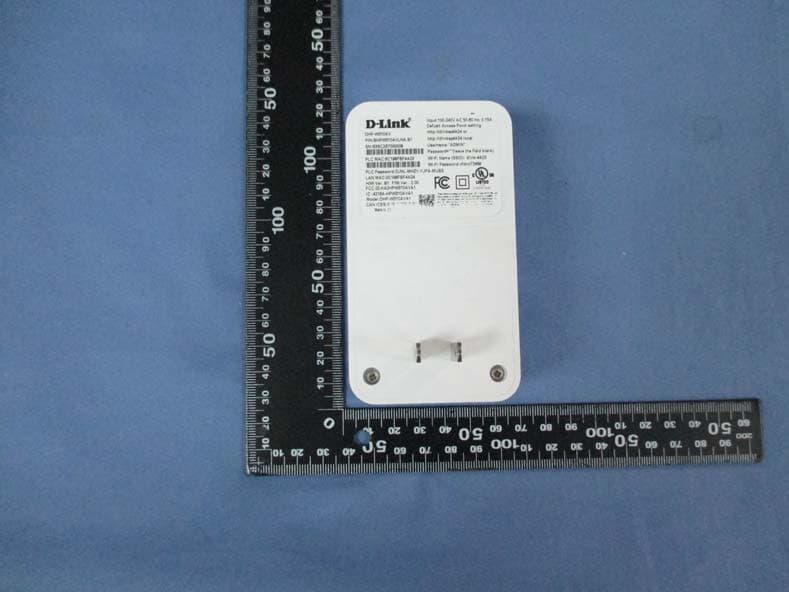
Click to zoom
Application Details
- Equipment Class
- DTS - Digital Transmission System
- Date of Grant
- Nov 06, 2014
- Application Purpose
- Original Equipment
- Date of Application
- Nov 06, 2014
- Equipment Note
- Powerline AV 500 Wireless N Mini Extender
- Frequency Range
- 2412.00000000 - 2462.00000000
- Company
- D-Link Corporation
- Country
- United States
Documents & Files
Document Text
Text extracted from the exhibit documents filed with the FCC. Open a document above to read the original.
Users Manual
Quick Installation Guide DHP-W310AV PowerLine AV500 Wireless N Mini Extender Version 2.00 | August 29, 2014 Краткое руководство по установке Guía de Instalación Rápida Guia de Instalação Rápida 快速安裝指南 Petunjuk Pemasangan Cepat DHP-W310AV 2 ENGLISH Package Contents Wi-Fi Configuration Note Wi-Fi Configuration Card CAT5 Ethernet Cable PowerLine AV500 Wireless N Mini Extender Installation CD-ROM Hardware Installation 1. Plug the DHP-W310AV Powerline AV500 Wireless N Mini Extender into a wall outlet in a place you want to extend your network. ROOM C DHP-W310AV iPad Notebook 3 DHP-W310AV ENGLISH Hardware Installation 2. Connect the included Ethernet cable to your DHP-W310AV and computer. You may also connect to the DHP-W310AV over Wi-Fi with the information on the Wireless Configuration Card. 3. Your computer and DHP-W310AV are now connected. Please refer to “First- time Configuration” on the next page to connect your DHP-W310AV with your existing Powerline network. The device complies with Part 15 of the FCC Rules. Operation is subject to the following two conditions: (1)The device may not cause harmful interference, and (2)this device must accept any interference received, including interference that may cause undesired operation. ROOM AROOM BROOM C DHP-W310AV DHP-W310AV DHP-308AV RouterInternet NotebookNotebook iPadiPad DHP-W310AV 4 ENGLISH First-time Configuration 1. Use your web browser to go to: Windows: http://dlinkapWXYZ or http://dlinkap Mac OS: http://dlinkapWXYZ.local. or http://dlinkap.local. Where WXYZ is the last 4 digits of the MAC address. The full address is available on the included Wireless Configuration Card. 2. Select ADMIN for the User Name and leave the Password blank. 3. From the landing page, start the Setup Wizard for Powerline Connection. 4. When prompted, press the Common Connect Button for 2 seconds on your existing device to connect it to the DHP-W310AV. Note: If you have not previously secured your existing Powerline network, you will need to set up security for all of your existing Powerline devices. Perform the following steps for each device: press the Common Connect Button on the DHP-W310AV, then press the Simple Connect Button on your existing Powerline device within 2 minutes. 5. Follow the wizard’s steps to set up your Powerline network. For more detailed support, please refer to the User Manual. 5 DHP-W310AV ENGLISH Frequently Asked Questions Q: Why can’t my DHP-W310AV find my Powerline network? • Be sure you are plugging directly into a wall outlet. Plugging into anything else may slow or stop the connection. • The electrical wiring must have a direct connection. For example, Powerline connections may not be available across a street or to different units in an apartment building. Q: My connection is erratic and sometimes cuts out or is slow, why? • Try to keep nearby outlets free of other devices, especially chargers and hair dryers, to minimize electrical interference. Q: How do I find my wireless network? Why does it have such a weird name? Can I change it? • You can find the Wi-Fi name (SSID) and password on the Wireless Configura- tion Card. Common names and passwords like dlink or password are avoided for security purposes. • You can change your wireless settings by navigating a web browser to http://dlinkapWXYZ.local. then Setup then Wireless Settings. WXYZ is an example, the real address is on your configuration card. Q: Can I use only the DHP-W310AV to get online? • At least two Powerline devices work together to create a network. They com- municate over your electrical wiring, but you still need an Internet connec- tion from a router and/or modem. Q: Can I use more than one DHP-W310AV device at a time? • Yes you can! D-Link offers a host of Powerline devices that include adapters, extenders, and routers. DHP-W310AV 6 ENGLISH Technical Support You can find software updates and user documentation on the D-Link website. Tech Support for customers in Australia: Tel: 1300-766-868 24/7 Technical Support Web: http://www.dlink.com.au E-mail: [email protected] India: Tel: +91-832-2856000 Toll Free 1800-233-0000 Web: www.dlink.co.in E-Mail: [email protected] Singapore, Thailand, Indonesia, Malaysia, Philippines, Vietnam: Singapore - www.dlink.com.sg Thailand - www.dlink.co.th Indonesia - www.dlink.co.id Malaysia - www.dlink.com.my Philippines - www.dlink.com.ph Vietnam - www.dlink.com.vn Korea: Tel : +82-2-2028-1810 Monday to Friday 9:00am to 6:00pm Web : http://d-link.co.kr E-mail : [email protected] New Zealand: Tel: 0800-900-900 24/7 Technical Support Web: http://www.dlink.co.nz E-mail: [email protected] South Africa and Sub Sahara Region: Tel: +27 12 661 2025 08600 DLINK (for South Africa only) Monday to Friday 8:30am to 9:00pm South Africa Time Web: http://www.d-link.co.za E-mail: [email protected] D-Link Middle East - Dubai, U.A.E. Plot No. S31102, Jebel Ali Free Zone South, P.O.Box 18224, Dubai, U.A.E. Tel: +971-4-8809022 Fax: +971-4-8809066 / 8809069 Technical Support: +971-4-8809033 General Inquiries: [email protected] Tech Support: [email protected] Egypt 1, Makram Ebeid Street - City Lights Building Nasrcity - Cairo, Egypt Floor 6, office C2 Tel.: +2 02 26718375 - +2 02 26717280 Technical Support: +2 02 26738470 General Inquiries: [email protected] Tech Support: [email protected] Kingdom of Saudi Arabia Office # 84 , Al Khaleej Building ( Mujamathu Al-Khaleej) Opp. King Fahd Road, Olaya Riyadh - Saudi Arabia Tel: +966 1121 70008 Technical Support: +966 1121 70009 General Inquiries: info.sa@ dlinkmea.com Tech Support: support.sa@ dlinkmea.com Pakistan Islamabad Office: 61-A, Jinnah Avenue, Blue Area, Suite # 11, EBC, Saudi Pak Tower, Islamabad - Pakistan Tel.: +92-51-2800397, 2800398 Fax: +92-51-2800399 7 DHP-W310AV ENGLISH Technical Support You can find software updates and user documentation on the D-Link website. Tech Support for customers in Karachi Office: D-147/1, KDA Scheme # 1, Opposite Mudassir Park, Karsaz…
Text truncated - open the document above for the full version.
Attestation Statements
Federal Communications Commission Authorization and Evaluation Division 09,26, 2014 ATTESTATION FCC ID: KA2HPW310AVB1 Product description: Powerline AV 500 Wireless N Mini Extender Model: DHP-W310AV, DHP-W310AVB1 We don't provide any controls or software to allow operation outside the USA frequency band when we sell this product in USA. We also promise that the end user or installer will not be able to change countries. For United States only channels 1-11 will be available. Best Regards Shinglin Chung / Associate Vice President D-Link Corporation Tel: +886-2-66000123#5819 Fax: +886-2-55509988 E-mail: [email protected]
Cover Letter(s)
Declaration of Authorization We Name: D-Link Corporation Address: No.289, Sinhu 3rd Rd., Neihu District, Taipei City 114, Taiwan, R.O.C City: Country: Declare that: Name Representative of agent: Gene Chang Agent Company name: QuieTek Corporation Address: 2F, No. 345, Xinhu 2nd Rd., Neihu District, City: Taipei City 114, Country: Taiwan, R.O.C. is authorized to apply for Certification of the following product(s): Product description: Powerline AV 500 Wireless N Mini Extender Type designation: DHP-W310AV, DHP-W310AVB1 Trademark: D-Link FCC ID: KA2HPW310AVB1 on our behalf. Date: 2014/09/26 City: Signature: Shinglin Chung / Associate Vice President D-Link Corporation Tel: +886-2-66000123#5819 Fax: +886-2-55509988 E-mail: [email protected]
External Photos
Report No: 1490239R-RFUSP26V00 Page: 232 of 245 Attachement EUT Photograph (1) EUT Photo (2) EUT Photo Report No: 1490239R-RFUSP26V00 Page: 233 of 245 (3) EUT Photo (4) EUT Photo Report No: 1490239R-RFUSP26V00 Page: 234 of 245 (5) EUT Photo (6) EUT Photo Report No: 1490239R-RFUSP26V00 Page: 235 of 245 (7) EUT Photo (8) EUT Photo Report No: 1490239R-RFUSP26V00 Page: 236 of 245 (9) EUT Photo (10) EUT Photo
ID Label/Location Info
FCC ID.: KA2HPW310AVB1 FCC ID AND DoC Label The FCC ID and DoC Label will be placed on the equipment as shown in the photograph below.
Internal Photos
Report No: 1490239R-RFUSP26V00 Page: 237 of 245 (11) EUT Photo (12) EUT Photo Report No: 1490239R-RFUSP26V00 Page: 238 of 245 (13) EUT Photo (14) EUT Photo Report No: 1490239R-RFUSP26V00 Page: 239 of 245 (15) EUT Photo (16) EUT Photo Report No: 1490239R-RFUSP26V00 Page: 240 of 245 (17) EUT Photo (18) EUT Photo Report No: 1490239R-RFUSP26V00 Page: 241 of 245 (19) EUT Photo (MB) Report No: 1490239R-RFUSP26V00 Page: 242 of 245 (20) EUT Photo (MB) Report No: 1490239R-RFUSP26V00 Page: 243 of 245 (21) EUT Photo (MB) Report No: 1490239R-RFUSP26V00 Page: 244 of 245 (22) EUT Photo (PIFA Antenna) (23) EUT Photo (PCB Antenna) Report No: 1490239R-RFUSP26V00 Page: 245 of 245 (24) EUT Photo (PCB Antenna)
RF Exposure Info
Report No. 1490239R-RF-US-Exp Page: 1 of 4 RF Exposure Evaluation Declaration Product Name : Powerline AV 500 Wireless N Mini Extender Model No. : DHP-W310AV, DHP-W310AVB1 FCC ID. : KA2HPW310AVB1 Applicant : D-Link Corporation Address : No.289, Sinhu 3rd Rd., Neihu District, Taipei City 114, Taiwan, R.O.C. Date of Receipt : 2014/09/05 Date of Declaration : 2014/10/07 Report No. : 1490239R-RF-US-Exp Report Version : V1.0 The declaration results relate only to the samples calculated. The declaration shall not be reproduced except in full without the written approval of QuieTek Corporation. Report No. 1490239R-RF-US-Exp Page: 2 of 4 1. RF Exposure Evaluation 1.1. Limits According to FCC 1.1310: The criteria listed in the following table shall be used to evaluate the environment impact of human exposure to radio frequency (RF) radiation as specified in 1.1307(b) LIMITS FOR MAXIMUM PERMISSIBLE EXPOSURE (MPE) Frequency Range (MHz) Electric Field Strength (V/m) Magnetic Field Strength (A/m) Power Density (mW/cm 2 ) Average Time (Minutes) (A) Limits for Occupational/ Control Exposures 300-1500 -- -- F/300 6 1500-100,000 -- -- 5 6 (B) Limits for General Population/ Uncontrolled Exposures 300-1500 -- -- F/1500 6 1500-100,000 -- -- 1 30 F= Frequency in MHz Friis Formula Friis transmission formula: Pd = (Pout*G)/(4*pi*r 2 ) Where Pd = power density in mW/cm 2 Pout = output power to antenna in mW G = gain of antenna in linear scale Pi = 3.1416 R = distance between observation point and center of the radiator in cm Pd id the limit of MPE, 1 mW/cm 2 . If we know the maximum gain of the antenna and the total power input to the antenna, through the calculation, we will know the distance r where the MPE limit is reached. 1.2. Test Procedure Software provided by client enabled the EUT to transmit and receive data at lowest, middle and highest channel individually. The temperature and related humidity: 18°Cand 78% RH. Report No. 1490239R-RF-US-Exp Page: 3 of 4 1.3. Test Result of RF Exposure Evaluation Product Powerline AV 500 Wireless N Mini Extender Test Mode Transmit Test Condition RF Exposure Evaluation Antenna Gain Antenna Gain: The maximum Gain measured in fully anechoic chamber are 2.98dBi(or 1.99) and 1.85dBi(or 1.53) in linear scale. Output Power into Antenna & RF Exposure Evaluation Distance: IEEE 802.11b WLAN Function Channel Channel Frequency (MHz) Output Power to Antenna (mW) Power Density at R = 20 cm (mW/cm 2 ) 1 2412 50.6991 0.02007 6 2437 53.8270 0.02131 11 2462 55.3350 0.02191 IEEE 802.11g WLAN Function Channel Channel Frequency (MHz) Output Power to Antenna (mW) Power Density at R = 20 cm (mW/cm 2 ) 1 2412 210.8628 0.08348 6 2437 304.0885 0.12039 11 2462 261.8183 0.10365 The power density Pd (4th column) at a distance of 20 cm calculated from the Friis transmission formula is far below the limit of 1 mW/cm 2 . Report No. 1490239R-RF-US-Exp Page: 4 of 4 Product Powerline AV 500 Wireless N Mini Extender Test Mode Transmit Test Condition RF Exposure Evaluation Antenna Gain Antenna Gain: The maximum Gain measured in fully anechoic chamber are 2.98dBi(or 1.99) and 1.85dBi(or 1.53) in linear scale. Output Power into Antenna & RF Exposure Evaluation Distance: IEEE 802.11n (20MHz) ANT 0+1 WLAN Function Channel Channel Frequency (MHz) Output Power to Antenna (mW) Power Density at R = 20 cm (mW/cm 2 ) 1 2412 267.3006 0.10582 6 2437 553.3501 0.21907 11 2462 359.7493 0.14242 The power density Pd (4th column) at a distance of 20 cm calculated from the Friis transmission formula is far below the limit of 1 mW/cm 2 . IEEE 802.11n (40MHz) ANT 0+1 WLAN Function Channel Channel Frequency (MHz) Output Power to Antenna (mW) Power Density at R = 20 cm (mW/cm 2 ) 3 2422 145.2112 0.05749 6 2437 296.4831 0.11738 9 2452 182.3896 0.07221 The power density Pd (4th column) at a distance of 20 cm calculated from the Friis transmission formula is far below the limit of 1 mW/cm 2 .
Test Report
Report No: 1490239R-RFUSP26V00 Page: 1 of 245 FCC Test Report Product Name : Powerline AV 500 Wireless N Mini Extender Model No. : DHP-W310AV, DHP-W310AVB1 FCC ID. : KA2HPW310AVB1 Applicant : D-Link Corporation Address : No.289, Sinhu 3rd Rd., Neihu District, Taipei City 114, Taiwan, R.O.C. Date of Receipt: 2014/09/05 Issued Date :2014/10/07 Report No. :1490239R-RFUSP26V00 Report Version : V1.0 The test results relate only to the samples tested. The test report shall not be reproduced except in full without the written approval of QuieTek Corporation. Report No: 1490239R-RFUSP26V00 Page: 2 of 245 Test Report Certification Issued Date : 2014/10/07 Report No. : 1490239R-RFUSP26V00 Product Name : Powerline AV 500 Wireless N Mini Extender Applicant : D-Link Corporation Address : No.289, Sinhu 3rd Rd., Neihu District, Taipei City 114, Taiwan, R.O.C. Model No. : DHP-W310AV, DHP-W310AVB1 FCC ID. : KA2HPW310AVB1 EUT Test Voltage : AC 100-240V, 50/60Hz Trade Name : D-Link Applicable Standard : FCC CFR Title 47 Part 15 Subpart C Section 15.247: 2013 ANSI C63.10: 2013 Test Result : Complied The test results relate only to the samples tested. The test report shall not be reproduced except in full without the written approval of QuieTek Corporation. Documented By : ( Carol Tsai / Engineering Adm. Assistant ) Reviewed By : ( JuBo Shen / Engineer) Approved By : ( Roy Wang / Director ) Report No: 1490239R-RFUSP26V00 Page: 3 of 245 Laboratory Information We, QuieTek Corporation, are an independent RF consultancy that was established the whole facility in our laboratories. The test facility has been accredited/accepted (audited or listed) by the following related bodies in compliance with ISO 17025 specified testing scopes: The related certificate for our laboratories about the test site and management system can be downloaded from QuieTek Corporation’s Web Site:http://www.quietek.com/tw/ctg/cts/accreditations.htm The address and introduction of QuieTek Corporation’s laboratories can be founded in our Web site : http://www.quietek.com/ If you have any comments, Please don’t hesitate to contact us. Our contact information is as below: HsinChu Testing Laboratory: No.75-2, 3rd Lin, Wangye Keng, Yonghxing Tsuen, Qionglin Shiang, Hsinchu County 307, Taiwan, R.O.C. TEL:+886-3-592-8858 / FAX:+886-3-592-8859 E-Mail : [email protected] LinKou Testing Laboratory: No.5-22, Ruishukeng, Linkou Dist., New Taipei City 24451, Taiwan, R.O.C. TEL : 886-2-8601-3788 / FAX : 886-2-8601-3789 E-Mail : [email protected] Taiwan R.O.C. : TAF, Accreditation Number: 1313 NCC, Certificate No : NCC-RCB-07 USA : FCC, Registration Number: 365520 Canada : IC, Submission No: 150981 Report No: 1490239R-RFUSP26V00 Page: 4 of 245 TABLE OF CONTENTS Description Page 1. General Information.............................................................................................................. 6 1.1. EUT Description ............................................................................................................. 6 1.2. Test Mode ..................................................................................................................... 10 1.3. Tested System Details .................................................................................................. 11 1.4. Configuration of tested System .................................................................................... 11 1.5. EUT Exercise Software ................................................................................................ 12 1.6. Test Facility...................................................................................................................13 2. Conducted Emission .......................................................................................................... 14 2.1. Test Equipment............................................................................................................. 14 2.2. Test Setup .................................................................................................................... 14 2.3. Limits ............................................................................................................................ 15 2.4. Test Procedure ............................................................................................................. 15 2.5. Test Specification.......................................................................................................... 15 2.6. Uncertainty ................................................................................................................... 15 2.7. Test Result....................................................................................................................16 2.8. Test Photo .................................................................................................................... 18 3. Peak Power Output ............................................................................................................ 19 3.1. Test Equipment............................................................................................................. 19 3.2. Test Setup .................................................................................................................... 19 3.3. Test procedures ............................................................................................................ 19 3.4. Limits ............................................................................................................................ 19 3.5. Test Specification.......................................................................................................... 19 3.6. Uncertainty ................................................................................................................... 19 3.7. Test Result....................................................................................................................20 4. Radiated Emission ....…
Text truncated - open the document above for the full version.
Test Report
Report No: 1490239R-RFUSP26V00 Page: 130 of 245 2422MHz (30MHz-1GHz)- 802.11n (40MHz)(ANT 0) 2422MHz (1GHz-8GHz) -802.11n (40MHz)(ANT 0) Report No: 1490239R-RFUSP26V00 Page: 131 of 245 2422MHz (8GHz-16GHz) -802.11n (40MHz)(ANT 0) 2422MHz (16GHz-25GHz) -802.11n (40MHz)(ANT 0) Report No: 1490239R-RFUSP26V00 Page: 132 of 245 2437MHz (30MHz-1GHz)- 802.11n (40MHz)(ANT 0) 2437MHz (1GHz-8GHz) -802.11n (40MHz) (ANT 0) Report No: 1490239R-RFUSP26V00 Page: 133 of 245 2437MHz (8GHz-16GHz) -802.11n (40MHz)(ANT 0) 2437MHz (16GHz-25GHz) -802.11n (40MHz)(ANT 0) Report No: 1490239R-RFUSP26V00 Page: 134 of 245 2452MHz (30MHz-1GHz)- 802.11n (40MHz)(ANT 0) 2452MHz (1GHz-8GHz) -802.11n (40MHz)(ANT 0) Report No: 1490239R-RFUSP26V00 Page: 135 of 245 2452MHz (8GHz-16GHz) -802.11n (40MHz)(ANT 0) 2452MHz (16GHz-25GHz) -802.11n (40MHz)(ANT 0) Report No: 1490239R-RFUSP26V00 Page: 136 of 245 2422MHz (30MHz-1GHz)- 802.11n (40MHz)(ANT 1) 2422MHz (1GHz-8GHz) -802.11n (40MHz)(ANT 1) Report No: 1490239R-RFUSP26V00 Page: 137 of 245 2422MHz (8GHz-16GHz) -802.11n (40MHz)(ANT 1) 2422MHz (16GHz-25GHz) -802.11n (40MHz)(ANT 1) Report No: 1490239R-RFUSP26V00 Page: 138 of 245 2437MHz (30MHz-1GHz)- 802.11n (40MHz)(ANT 1) 2437MHz (1GHz-8GHz) -802.11n (40MHz) (ANT 1) Report No: 1490239R-RFUSP26V00 Page: 139 of 245 2437MHz (8GHz-16GHz) -802.11n (40MHz)(ANT 1) 2437MHz (16GHz-25GHz) -802.11n (40MHz)(ANT 1) Report No: 1490239R-RFUSP26V00 Page: 140 of 245 2452MHz (30MHz-1GHz)- 802.11n (40MHz)(ANT 1) 2452MHz (1GHz-8GHz) -802.11n (40MHz)(ANT 1) Report No: 1490239R-RFUSP26V00 Page: 141 of 245 2452MHz (8GHz-16GHz) -802.11n (40MHz)(ANT 1) 2452MHz (16GHz-25GHz) -802.11n (40MHz)(ANT 1) Report No: 1490239R-RFUSP26V00 Page: 142 of 245 6. Radiated Emission Band Edge 6.1. Test Equipment The following test equipments are used during the test: Radiated Emission Band Edge / CB1 Instrument Manufacturer Model No. Serial No Next Cal. Date Double Ridged Guide Horn Antenna Schwarzback BBHA 9120 D743 2015/02/12 Spectrum Analyzer Agilent E4440A MY46187335 2015/01/12 k Type Cable Huber Suhner Sucoflex 102 25623/2 2015/02/10 Note: 1. All equipments that need to calibrate are with calibration period of 1 year. 6.2. Test Setup Report No: 1490239R-RFUSP26V00 Page: 143 of 245 6.3. Limits Emissions radiated outside of the specified frequency bands, except for harmonics, shall be attenuated by at least 20dB below the level of the fundamental or to the general radiated emission limits in paragraph 15.209, whichever is the lesser attenuation. 6.4. Test Procedure The EUT was setup according to ANSI C63.10: 2013 and tested according to DTS test procedure of KDB558074 v03r02 for compliance to FCC 47CFR 15.247 requirements. The EUT and its simulators are placed on a turn table which is 0.8 meter above ground. The turn table can rotate 360 degrees to determine the position of the maximum emission level. The EUT was positioned such that the distance from antenna to the EUT was 3 meters. The antenna can move up and down between 1 meter and 4 meters to find out the maximum emission level. Both horizontal and vertical polarization of the antenna are set on measurement. In order to find the maximum emission, all of the interface cables must be manipulated according to ANSI C63.10: 2013 on radiated measurement. 6.5. Test Specification According to FCC Part 15 Subpart C Paragraph 15.247: 2013 6.6. Uncertainty The measurement uncertainty ± 3.9 dB above 1GHz Report No: 1490239R-RFUSP26V00 Page: 144 of 245 6.7. Test Result Radiated is defined as Site : CB1 Time : 2014/10/01 - 21:10 Limit : FCC_SpartC_15.209_03M_PK Margin : 6 Probe : CB1_FCC_EFS_1-18G-1_0901 - HORIZONTAL Power : AC 120V/60Hz EUT : Powerline AV 500 Wireless N Mini Extender Note : 802.11b_CH01 Frequency (MHz) Correct Factor (dB) Reading Level (dBuV) Measure Level (dBuV/m) Margin (dB) Limit (dBuV/m) Detector Type 1 2310.000 30.411 22.92653.337-20.663 74.000 PEAK 2 2388.867 31.229 25.03956.268-17.732 74.000 PEAK 3 2390.000 31.241 24.79456.035-17.965 74.000 PEAK 4 * 2411.827 31.468 72.984104.45130.451 74.000 PEAK 5 2483.500 31.980 22.95254.931-19.069 74.000 PEAK 6 2496.698 31.944 25.72057.664-16.336 74.000 PEAK 7 2500.000 31.934 23.24855.183-18.817 74.000 PEAK Note: 1. All readings above 1GHz are performed with peak and/or average measurements as necessary. 2. Peak measurements: RBW = 1MHz, VBW = 3 MHz, Sweep: Auto. 3. Average measurements: RBW = 1MHz, VBW = 10 Hz, Sweep: Auto. 4. “ * ”, means this data is the worst emission level. 5. Measurement Level = Reading Level + Correct Factor. 6. The average measurement was not performed when the peak measured data under the limit of average detection. Report No: 1490239R-RFUSP26V00 Page: 145 of 245 Site : CB1 Time : 2014/10/01 - 21:11 Limit : FCC_SpartC_15.209_03M_AV Margin : 6 Probe : CB1_FCC_EFS_1-18G-1_0901 - HORIZONTAL Power : AC 120V/60Hz EUT : Powerline AV 500 Wireless N Mini Extender Note : 802.11b_CH01 Frequency (MHz) Correct Factor (dB) Reading Level (dBuV) Measure Level (dBuV/m) Margin (dB) Limit (dBuV/m) Detector Type 1 2310.000 30.411 11.95142.362-11.638 54.000 AVERAGE 2 2388.970 31.230 13.52944.759-9.241 54.000 AVERAGE 3 2390.000 31.241 14.11745.358-8.642 54.000 AVERAGE 4 * 2411.315 31.462 69.904101.36647.366 54.000 AVERAGE 5 2483.500 31.980 12.34544.324-9.676 54.000 AVERAGE 6 2495.980 31.945 12.39144.337-9.663 54.000 AVERAGE 7 2500.000 31.934 12.33844.273-9.727 54.000 AVERAGE Note: 1. All readings above 1GHz are performed with peak and/or average measurements as necessary. 2. Peak measurements: RBW = 1MHz, VBW = 3 MHz, Sweep: Auto. 3. Average measurements: RBW = 1MHz, VBW = 10 Hz, Sweep: Auto. 4. “ * ”, means this data is the worst emission level. 5. Measurement Level = Reading Level + Correct Factor. 6. The average measurement was not performed when the peak measured data under the limit of average detection. Report No: 1490239R-RFUSP26V00 Page: 146 of 245 Site : CB1 Time : 2014/10/01 - 21:07 Limit : FCC_SpartC_15.209_03M_PK Margin : 6 Probe : CB1_FCC_EFS_1-18G-1…
Text truncated - open the document above for the full version.
Test Setup Photos
Report No: 1490239R-RFUSP26V00 Page: 18 of 245 2.8. Test Photo Test Mode : Mode 1: Transmit Description: Front View of Conducted Emission Test Setup Test Mode : Mode 1: Transmit Description: Back View of Conducted Emission Test Setup Report No: 1490239R-RFUSP26V00 Page: 84 of 245 4.8. Test Photo Test Mode : Mode 1: Transmit Description: Front View of Radiated Emission Test Setup (Bi-Log) Test Mode : Mode 1: Transmit Description: Back View of Radiated Emission Test Setup (Bi-Log) Report No: 1490239R-RFUSP26V00 Page: 85 of 245 Test Mode : Mode 1: Transmit Description: Front View of Radiated Emission Test Setup (Horn) Test Mode : Mode 1: Transmit Description: Back View of Radiated Emission Test Setup (Horn)
Contact Information
Applicant
Brett Adair(General Counsel)
Technical Contact
Test Firm
DEKRA TESTING AND CERTIFICATION CO., LTD.Warren Lin
Technical Specifications
| # | Rule Parts | Frequency Range | Power Output |
|---|---|---|---|
| 1 | 15C | 2.41 GHz - 2.46 GHz | 553.00 mW |
Other Applications from D-Link Corporation

KA2CS6012A1
Jul 07, 20262K Fixed Indoor Cloud Camera, 2K Fixed Indoor Wi-Fi Camera
Equipment Class
DTS - Digital Transmission SystemKA2AE65UA1
Mar 02, 2026Wi-Fi 7 BE6500 USB 3.0 Dongle
Equipment Class
NII - Unlicensed National Information Infrastructure TXKA2APE9560A1
Nov 17, 2025BE9500 Celling mount Access Point
Equipment Class
6ID - 15E 6 GHz Low Power Indoor Access PointKA2AX9UA1
Dec 04, 2024AX900 Wi-Fi 6 USB Adapter, Wi-Fi 6 AX900 USB 2.0 Dongle
Equipment Class
DSS - Part 15 Spread Spectrum TransmitterKA2AC13UA1
Dec 04, 2024AC1300 Wi-Fi 5 USB Adapter, Wi-Fi 5 AC1300 USB 2.0 Dongle
Equipment Class
DTS - Digital Transmission System