KA2IR602LA1Wireless N150 Cloud Router
D-Link Corporation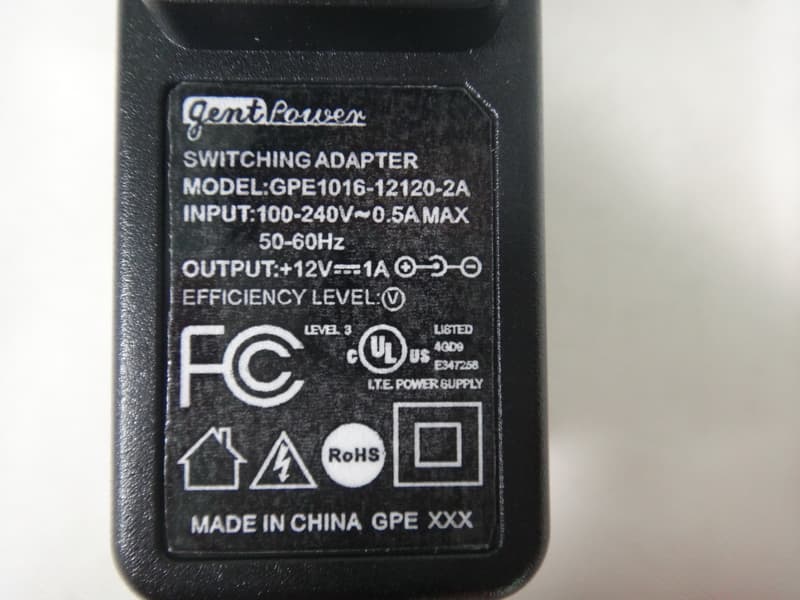
Click to zoom
Application Details
- Equipment Class
- DTS - Digital Transmission System
- Date of Grant
- Nov 06, 2012
- Application Purpose
- Original Equipment
- Date of Application
- Nov 06, 2012
- Equipment Note
- Wireless N150 Cloud Router
- Frequency Range
- 2422.00000000 - 2452.00000000
- Company
- D-Link Corporation
- Country
- United States
Documents & Files
Document Text
Text extracted from the exhibit documents filed with the FCC. Open a document above to read the original.
Users Manual
DIR-602L D-Link reserves the right to revise this publication and to make changes in the content hereof without obligation to notify any person or organization of such revisions or changes. Preface Trademarks D-Link and the D-Link logo are trademarks or registered trademarks of D-Link Corporation or its subsidiaries in the United States or other countries. All other company or product names mentioned herein are trademarks or registered trademarks of their respective companies. Copyright © 2012 by D-Link Systems, Inc. All rights reserved. This publication may not be reproduced, in whole or in part, without prior expressed written permission from D-Link Systems, Inc. Section 1 - Product Overview Product Overview Package Contents DIR-602L Wireless N150 Cloud Router Power Adapter Ethernet Cable Quick Installation Guide Check for the supplied accessories below: Note: Using a power supply with a different voltage rating than the one included with the product, will cause damage and void the warranty for this product. Section 1 - Product Overview System Requirements Network.Requirements • An Ethernet-based Cable or DSL modem • IEEE 802.11n or 802.11g wireless clients • 10/100 Ethernet Web-based.Configuration. Utility.Requirements Computer.with.the.following: • Windows®, Macintosh, or Linux-based operating system • An installed Ethernet adapter Browser.Requirements: • Internet Explorer 6.0 or higher • Chrome 2.0 or higher • Firefox 3.0 or higher • Safari 3.0 or higher (with Java 1.3.1 or higher) Windows®.Users: Make sure you have the latest version of Java installed. Visit www.java.com to download the latest version. CD.Installation.Wizard. Requirements Computer.with.the.following: • Windows® 7, Vista®, or XP with Service Pack 2 • An installed Ethernet adapter Section 1 - Product Overview Features • Internet Connectivity - In conjunction with a DSL or Cable Modem, this device provides high-speed Internet connectivity to your local network for up to four wired devices. • Wireless LAN functionality - This router supports features like WMM, RF Output Level Control, WPS, and much more. • Networking - This router comes with one WAN port and four LAN ports that enable up to four computers on your local network to be connected. • Wireless Distribution System (WDS) mode- The router supports WDS where it can extend the network coverage from another router. • Advanced Security - The router also supports a range of security features like Network Filtering, Access Control, Website Filtering, Inbound Filtering, and SPI. • IPv6 - This router supports local IPv6 support and IPv6 Internet Connection. • User-friendly Setup Wizard - your router qickly and conveniently. The DIR-602L’s easy-to-use Web-based user interface lets you manage and con gure Section 2 - Hardware Installation Wireless Installation Considerations The router lets you access your network using a wireless connection from virtually anywhere within the operating range of your wireless network. Keep in mind, however, that the number, thickness and location of walls, ceilings, or other objects that the wireless signals must pass through, may limit the range. Ranges vary depending on the types of materials and background RF (radio frequency) noise in your home or office. The key to maximizing the wireless range is to follow these basic guidelines: 1. Keep the number of walls and ceilings between the D-Link router and other network devices to a minimum. Each wall or ceiling can reduce your adapter’s range from 3 to 90 feet (1 to 30 meters.) Position your devices so that the number of walls and/or ceilings is minimized. 2. Be aware of the direct line between network devices. A wall that is 1.5 feet thick (0.5 meters), at a 45-degree angle appears to be almost 3 feet (1 meter) thick. At a 2-degree angle it looks over 42 feet (14 meters) thick. Position devices so that the signal will travel straight through a wall or ceiling (instead of at an angle) for better reception. 3. Try to position access points, wireless routers, and computers so that the signal passes through open doorways and drywall. Materials such as glass, metal, brick, insulation, concrete and water can affect wireless performance. Large objects such as fish tanks, mirrors, file cabinets, metal doors and aluminum studs may also have a negative effect on range. 4. Keep your product at least 3 to 6 feet (1-2 meters) away from electrical devices or appliances that generate RF noise. 5. If you are using 2.4 GHz cordless phones, make sure that the 2.4 GHz phone base is as far away from your wireless device as possible. The base transmits a signal even if the phone in not in use. In some cases, cordless phones, X-10 wireless devices, and electronic equipment such as ceiling fans, fluorescent lights, and home security systems may dramatically degrade wireless connectivity. Section 2 - Hardware Installation Connect to Cable/DSL/Satellite Modem If you are connecting the router to a Cable/DSL/Satellite Modem, please follow the steps below: 1. Place the router in an open and central location. Do not plug the power adapter into the router. 2. Turn the power off on your modem. If there is no on/off switch, unplug the modem’s power adapter. Shut down your computer. 3. Unplug the Ethernet cable (that connects your computer to your modem) from your computer and place it into the Internet port on the router. 4. Plug an Ethernet cable into one of the LAN ports on the router. Plug the other end into the Ethernet port on your computer. 5. Turn on or plug in your modem. Wait for the modem to boot (about 30 seconds). 6. Plug the power adapter into the router and connect to an outlet or power strip. Wait about 30 seconds for the router to boot up. 7. Turn on your computer. 8. Verify that the Power LED on the router is lit. If the Power LED does not light up, make sure your computer, modem, and router are powered, on and verify that the cables connected correctly. 9. In a later section in this manual we’ll discu…
Text truncated - open the document above for the full version.
External Photos
Neutron Engineering Inc. Report No.: NEI-FCCP-1-1209C116 Page 133 of 136 9. EUT PHOTO Neutron Engineering Inc. Report No.: NEI-FCCP-1-1209C116 Page 134 of 136 Adapter: D-Link / AMS9-1201000FU2 Neutron Engineering Inc. Report No.: NEI-FCCP-1-1209C116 Page 135 of 136 Adapter: D-Link / CAP012121US Neutron Engineering Inc. Report No.: NEI-FCCP-1-1209C116 Page 136 of 136 Adapter: gent Power / GPE1016-12120-2A
ID Label/Location Info
DIR-602L A1Device label 970000012010G Hoho(ID:1319) Leon Peng Leon Peng 2012/09/07 2012/09/07 2012/09/07
Internal Photos
Neutron Engineering Inc. Project No.: 1209C116 Page 2 of 5 Neutron Engineering Inc. Project No.: 1209C116 Page 3 of 5 Neutron Engineering Inc. Project No.: 1209C116 Page 4 of 5 Neutron Engineering Inc. Project No.: 1209C116 Page 5 of 5
Test Report
Neutron Engineering Inc. Report No.: NEI-FCCP-1-1209C116 Page 1 of 137 FCC Radio Test Report FCC ID: KA2IR602LA1 This report concerns (check one) : Original Grant Class I Change Issued Date : Sep. 27, 2012 Project No. : 1209C116 Equipment : Wireless N150 Cloud Router Model Name : DIR-602L Applicant : D-LINK CORPORATION Address : No.289, Sinhu 3rd Rd., Neihu District, Taipei City 114, Taiwan, R.O.C. Tested by: Neutron Engineering Inc. EMC Laboratory Date of Receipt: Sep. 15, 2012 Date of Test: Sep. 15, 2012 ~ Sep. 26, 2012 Testing Engineer : (David Mao) Technical Manager : (Leo Hung) Authorized Signatory : (Steven Lu) Neutron Engineering Inc. No.3,Jinshagang 1st Road, ShiXia, Dalang Town, Dong Guan, China. TEL : (0769) 8318-3000 FAX : (0769) 8319-6000 Neutron Engineering Inc. Report No.: NEI-FCCP-1-1209C116 Page 2 of 137 Declaration Neutron represents to the client that testing is done in accordance with standard procedures as applicable and that test instruments used has been calibrated with the standards traceable to National Measurement Laboratory (NML) of R.O.C, or National Institute of Standards and Technology (NIST) of U.S.A. Neutron's reports apply only to the specific samples tested under conditions. It is manufacture’s responsibility to ensure that additional production units of this model are manufactured with the identical electrical and mechanical components. Neutronshall have no liability for any declarations, inferences o r generalizations drawn by the client or others from Neutron issued reports. Neutron’s reports must not be used by the client to claim product endorsement by the authorities or any agency of the Government. This report is the confidential property of the client. As a mutual protection to the clients, the public and Neutron-self, extracts from the test report shall not be reproduced except in full with Neutron’s authorized written approval. Neutron’s laboratory quality assurance procedures are in compliance with the ISO Guide 17025 requirements, and accredited by the conformity assessment authorities listed in this test report. Limitation For the use of the authority's logo is limited unless the Test Standard(s)/Scope(s)/Item(s) mentioned in this test report is (are) included in the conformity assessment authorities acceptance respective. Neutron Engineering Inc. Report No.: NEI-FCCP-1-1209C116 Page 3 of 137 Table of Contents Page 1 . CERTIFICATION 5 2 . SUMMARY OF TEST RESULTS 6 2.1 TEST FACILITY 7 2.2 MEASUREMENT UNCERTAINTY 7 3 . GENERAL INFORMATION 8 3.1 GENERAL DESCRIPTION OF EUT 8 3.2 DESCRIPTION OF TEST MODES 10 3.3 TABLE OF PARAMETERS OF TEXT SOFTWARE SETTING 11 3.4 BLOCK DIGRAM SHOWING THE CONFIGURATION OF SYSTEM TESTED 12 3.5 DESCRIPTION OF SUPPORT UNITS 14 4 . EMC EMISSION TEST 15 4.1 CONDUCTED EMISSION MEASUREMENT 15 4.1.1 POWER LINE CONDUCTED EMISSION LIMITS 15 4.1.2 MEASUREMENT INSTRUMENTS LIST AND SETTING 15 4.1.3 TEST PROCEDURE 16 4.1.4 DEVIATION FROM TEST STANDARD 16 4.1.5 TEST SETUP 16 4.1.6 EUT OPERATING CONDITIONS 16 4.1.7 TEST RESULTS 17 4.1.8. EUT TEST PHOTO 23 4.2 RADIATED EMISSION MEASUREMENT 24 4.2.1 RADIATED EMISSION LIMITS 24 4.2.2 MEASUREMENT INSTRUMENTS LIST ANS SETTING 25 4.2.3 TEST PROCEDURE 26 4.2.4 DEVIATION FROM TEST STANDARD 26 4.2.5 TEST SETUP 27 4.2.6 EUT OPERATING CONDITIONS 28 4.2.7 TEST RESULTS (BELOW 30MHZ) 29 4.2.8 TEST RESULTS (BETWEEN 30 – 1000 MHZ) 30 4.2.9 TEST RESULTS (ABOVE 1000 MHZ) 36 4.2.10. EUT TEST PHOTO 52 5 . BANDWIDTH TEST 52 5.1 APPLIED PROCEDURES / LIMIT 52 5.1.1 MEASUREMENT INSTRUMENTS LIST 52 5.1.2 TEST PROCEDURE 52 5.1.3 DEVIATION FROM STANDARD 52 5.1.4 TEST SETUP 52 5.1.5 EUT OPERATION CONDITIONS 52 Neutron Engineering Inc. Report No.: NEI-FCCP-1-1209C116 Page 4 of 137 Table of Contents Page 5.1.6 TEST RESULTS 52 5.1.7. EUT TEST PHOTO 52 6 . MAXIMUM OUTPUT POWER TEST 52 6.1 APPLIED PROCEDURES / LIMIT 52 6.1.1 MEASUREMENT INSTRUMENTS LIST 52 6.1.2 TEST PROCEDURE 52 6.1.3 DEVIATION FROM STANDARD 52 6.1.4 TEST SETUP 52 6.1.5 EUT OPERATION CONDITIONS 52 6.1.6 TEST RESULTS 52 6.1.7. EUT TEST PHOTO 52 7 . ANTENNA CONDUCTED SPURIOUS EMISSION 52 7.1 APPLIED PROCEDURES / LIMIT 52 7.1.1 MEASUREMENT INSTRUMENTS LIST 52 7.1.2 TEST PROCEDURE 52 7.1.3 DEVIATION FROM STANDARD 52 7.1.4 TEST SETUP 52 7.1.5 EUT OPERATION CONDITIONS 52 7.1.6 TEST RESULTS 52 7.1.7. EUT TEST PHOTO 52 8 . POWER SPECTRAL DENSITY TEST 52 8.1 APPLIED PROCEDURES / LIMIT 52 8.1.1 MEASUREMENT INSTRUMENTS LIST 52 8.1.2 TEST PROCEDURE 52 8.1.3 DEVIATION FROM STANDARD 52 8.1.4 TEST SETUP 52 8.1.5 EUT OPERATION CONDITIONS 52 8.1.6 TEST RESULTS 52 8.1.7. EUT TEST PHOTO 52 9 . EUT PHOTO 52 Neutron Engineering Inc. Report No.: NEI-FCCP-1-1209C116 Page 5 of 137 1. CERTIFICATION Equipment : Wireless N150 Cloud Router Brand Name : D-Link Model Name : DIR-602L Applicant : D-LINK CORPORATION Factory : Alpha Networks Inc. Address : Building D15, No.168, Guangfu Road, Chengfei Avenue, Industrial Centralization Development Zone (East Zone), QingYang Dist., Chengdu, 610092, China Date of Test : Sep. 15, 2012 ~ Sep. 26, 2012 Test Item : ENGINEERING SAMPLE Standards : FCC Part15, Subpart C(15.247) / ANSI C63.4-2009 The above equipment has been tested and found compliance with the requirement of the relative standards by Neutron Engineering Inc. EMC Laboratory. The test data, data evaluation, and equipment configuration contained in our test report (Ref No. NEI-FCCP-1-1209C116) were obtained utilizing the test procedures, test instruments, test sites that has been accredited by the Authority of NVLAP and TAF according to the ISO-17025 quality assessment standard and technical standard(s). Neutron Engineering Inc. Report No.: NEI-FCCP-1-1209C116 Page 6 of 137 2. SUMMARY OF TEST RESULTS Test procedures according to the technical standards: FCC Part15 (15.247) , Subpart C Standard Section Test Item Judgment Remark 15.207 Conducted Emission PASS 15.247(d) Antenna conducted Spurious EmissionPASS 15.247(a)(2) 6dB Bandwidth PASS 15.247(b)(3) Peak Output Power PASS 15…
Text truncated - open the document above for the full version.
Test Report
Neutron Engineering Inc. Report No.: NEI-FCCP-1-1209C116 Page 102 of 137 7. ANTENNA CONDUCTED SPURIOUS EMISSION 7.1 Applied procedures / limit 30dBc in any 100 kHz bandwidth outside the operating frequency band. In case the emission fall within the restricted band specified on 15.205(a), then the 15.209(a) limit in the table below has to be followed. Frequencies (MHz) Field Strength (micorvolts/meter) Measurement Distance (meters) 0.009~0.490 2400/F(KHz) 300 0.490~1.705 24000/F(KHz) 30 1.705~30.0 30 30 30~88 100 3 88~216 150 3 216~960 200 3 Above 960 500 3 7.1.1 MEASUREMENT INSTRUMENTS LIST Item Kind of Equipment Manufacturer Type No.Serial No.Last Calibration Next Calibration 1 Spectrum Analyzer R&S FSP_40 100185 Nov.26.2011 Nov.25.2012 Remark: “N/A” denotes no model name, serial no. or calibration specified. 7.1.2 TEST PROCEDURE a. The EUT was directly connected to the spectrum analyzer and antenna output port as show in the block diagram below, b. Spectrum Setting : RBW= 100KHz, VBW=100KHz, Sweep time = 10 ms. 7.1.3 DEVIATION FROM STANDARD No deviation. 7.1.4 TEST SETUP 7.1.5 EUT OPERATION CONDITIONS The EUT tested system was configured as the statements of 4.1.6 Unless otherwise a special operating condition is specified in the follows during the testing. Neutron Engineering Inc. Report No.: NEI-FCCP-1-1209C116 Page 103 of 137 7.1.6 TEST RESULTS EUT: Wireless N150 Cloud Router Model Name : DIR-602L Temperature: 24 °C Relative Humidity: 60 % Pressure: 1016 hPa Test Voltage : AC 120V/60Hz Test Mode : TX B MODE /CH01, CH06 , CH11 Channel of Worst Data: CH01 The max. radio frequency power in any 100kHz bandwidth outside the frequency band The max. radio frequency power in any 100 kHz bandwidth outside the frequency band. FREQUENCY(MHz) POWER(dBm) FREQUENCY(MHz) POWER(dBm) 2400.00 -41.80 2488.80 -45.91 Result In any 100kHz bandwidth outside the frequency band, the radio frequency power is at least 20dB below that in the 100kHz bandwidth within the band that contains the highest lever of the desired power. Neutron Engineering Inc. Report No.: NEI-FCCP-1-1209C116 Page 104 of 137 TX B mode CH01 TX B mode CH11 Neutron Engineering Inc. Report No.: NEI-FCCP-1-1209C116 Page 105 of 137 TX B mode CH01 (30M~1000MHz) TX B mode CH01 (1000MHz~10 th Harmonic) Neutron Engineering Inc. Report No.: NEI-FCCP-1-1209C116 Page 106 of 137 TX B mode CH06 (30M~1000MHz) TX B mode CH06 (1000MHz~10 th Harmonic) Neutron Engineering Inc. Report No.: NEI-FCCP-1-1209C116 Page 107 of 137 TX B mode CH11 (30M~1000MHz) TX B mode CH11 (1000MHz~10 th Harmonic) Neutron Engineering Inc. Report No.: NEI-FCCP-1-1209C116 Page 108 of 137 EUT: Wireless N150 Cloud Router Model Name : DIR-602L Temperature: 24 °C Relative Humidity: 60 % Pressure: 1016 hPa Test Voltage : AC 120V/60Hz Test Mode : TX G MODE / CH01, CH06 , CH11 Channel of Worst Data: CH01 The max. radio frequency power in any 100kHz bandwidth within the frequency band The max. radio frequency power in any 100 kHz bandwidth outside the frequency band. FREQUENCY(MHz) POWER(dBm) FREQUENCY(MHz) POWER(dBm) 2400.00 -31.13 2483.50 -37.14 Result In any 100kHz bandwidth outside the frequency band, the radio frequency power is at least 20dB below that in the 100kHz bandwidth within the band that contains the highest lever of the desired power. Neutron Engineering Inc. Report No.: NEI-FCCP-1-1209C116 Page 109 of 137 TX G mode CH01 TX G mode CH11 Neutron Engineering Inc. Report No.: NEI-FCCP-1-1209C116 Page 110 of 137 TX G mode CH01 (30M~1000MHz) TX G mode CH01 (1000MHz~10 th Harmonic) Neutron Engineering Inc. Report No.: NEI-FCCP-1-1209C116 Page 111 of 137 TX G mode CH06 (30M~1000MHz) TX G mode CH06 (1000MHz~10 th Harmonic) Neutron Engineering Inc. Report No.: NEI-FCCP-1-1209C116 Page 112 of 137 TX G mode CH11 (30M~1000MHz) TX G mode CH11 (1000MHz~10 th Harmonic) Neutron Engineering Inc. Report No.: NEI-FCCP-1-1209C116 Page 113 of 137 EUT: Wireless N150 Cloud Router Model Name : DIR-602L Temperature: 24 °C Relative Humidity: 60 % Pressure: 1016 hPa Test Voltage : AC 120V/60Hz Test Mode : TX N-20M MODE / CH01, CH06 , CH11 Channel of Worst Data: CH01 The max. radio frequency power in any 100kHz bandwidth within the frequency band The max. radio frequency power in any 100 kHz bandwidth within the frequency band. FREQUENCY(MHz) POWER(dBm) FREQUENCY(MHz) POWER(dBm) 2400.00 -31.59 2483.50 -39.00 Result In any 100kHz bandwidth outside the frequency band, the radio frequency power is at least 20dB below that in the 100kHz bandwidth within the band that contains the highest lever of the desired power. Neutron Engineering Inc. Report No.: NEI-FCCP-1-1209C116 Page 114 of 137 TX HT20 mode CH01 TX HT20 mode CH11 Neutron Engineering Inc. Report No.: NEI-FCCP-1-1209C116 Page 115 of 137 TX HT20 mode CH01 (30M~1000MHz) TX HT20 mode CH01 (1000MHz~10 th Harmonic) Neutron Engineering Inc. Report No.: NEI-FCCP-1-1209C116 Page 116 of 137 TX HT20 mode CH06 (30M~1000MHz) TX HT20 mode CH06 (1000MHz~10 th Harmonic) Neutron Engineering Inc. Report No.: NEI-FCCP-1-1209C116 Page 117 of 137 TX HT20 mode CH11 (30M~1000MHz) TX HT20 mode CH11 (1000MHz~10 th Harmonic) Neutron Engineering Inc. Report No.: NEI-FCCP-1-1209C116 Page 118 of 137 EUT: Wireless N150 Cloud Router Model Name : DIR-602L Temperature: 24 °C Relative Humidity: 60 % Pressure: 1016 hPa Test Voltage : AC 120V/60Hz Test Mode : TX N-40M MODE /CH03, CH06, CH09 Channel of Worst Data: CH09 The max. radio frequency power in any 100kHz bandwidth within the frequency band The max. radio frequency power in any 100 kHz bandwidth outside the frequency band. FREQUENCY(MHz) POWER(dBm) FREQUENCY(MHz) POWER(dBm) 2400.00 -39.78 2486.00 -37.10 Result In any 100kHz bandwidth outside the frequency band, the radio frequency power is at least 20dB below that in the 100kHz bandwidth within the band that contains the highest lever of the desired power. Neutron Engineering Inc. Report No.: NEI-FCCP-1-1209C116 Page 119 of 137 TX HT40 mode CH03 TX HT40 mode CH09 Neutron Engi…
Text truncated - open the document above for the full version.
Test Setup Photos
Neutron Engineering Inc. Report No.: NEI-FCCP-1-1209C116 Page 23 of 136 4.1.8. EUT TEST PHOTO Conducted Measurement Photos Neutron Engineering Inc. Report No.: NEI-FCCP-1-1209C116 Page 84 of 136 4.2.10. EUT TEST PHOTO Radiated Measurement Photos 9K~ 30MHz Neutron Engineering Inc. Report No.: NEI-FCCP-1-1209C116 Page 85 of 136 Radiated Measurement Photos 30MHz~1000MHz Neutron Engineering Inc. Report No.: NEI-FCCP-1-1209C116 Page 86 of 136 Radiated Measurement Photos Above 1000MHz Neutron Engineering Inc. Report No.: NEI-FCCP-1-1209C116 Page 96 of 136 5.1.7. EUT TEST PHOTO BANDWIDTH Measurement Photos Neutron Engineering Inc. Report No.: NEI-FCCP-1-1209C116 Page 100 of 136 6.1.7. EUT TEST PHOTO MAXIMUM OUTPUT POWER Measurement Photos Neutron Engineering Inc. Report No.: NEI-FCCP-1-1209C116 Page 122 of 136 7.1.7. EUT TEST PHOTO ANTENNA CONDUCTED SPURIOUS EMISSION Measurement Photos Neutron Engineering Inc. Report No.: NEI-FCCP-1-1209C116 Page 132 of 136 8.1.7. EUT TEST PHOTO POWER SPECTRAL DENSITY Measurement Photos
Contact Information
Applicant
Brett Adair(General Counsel)
Test Firm
BTL Inc.Daisy Dai
Technical Specifications
| # | Rule Parts | Frequency Range | Power Output |
|---|---|---|---|
| 2 | 15C | 2.42 GHz - 2.45 GHz | 224.00 mW |
Other Applications from D-Link Corporation

KA2CS6012A1
Jul 07, 20262K Fixed Indoor Cloud Camera, 2K Fixed Indoor Wi-Fi Camera
Equipment Class
DTS - Digital Transmission SystemKA2AE65UA1
Mar 02, 2026Wi-Fi 7 BE6500 USB 3.0 Dongle
Equipment Class
NII - Unlicensed National Information Infrastructure TXKA2APE9560A1
Nov 17, 2025BE9500 Celling mount Access Point
Equipment Class
6ID - 15E 6 GHz Low Power Indoor Access PointKA2AX9UA1
Dec 04, 2024AX900 Wi-Fi 6 USB Adapter, Wi-Fi 6 AX900 USB 2.0 Dongle
Equipment Class
DSS - Part 15 Spread Spectrum TransmitterKA2AC13UA1
Dec 04, 2024AC1300 Wi-Fi 5 USB Adapter, Wi-Fi 5 AC1300 USB 2.0 Dongle
Equipment Class
DTS - Digital Transmission System