KA2IR815C1Wireless router
D-Link Corporation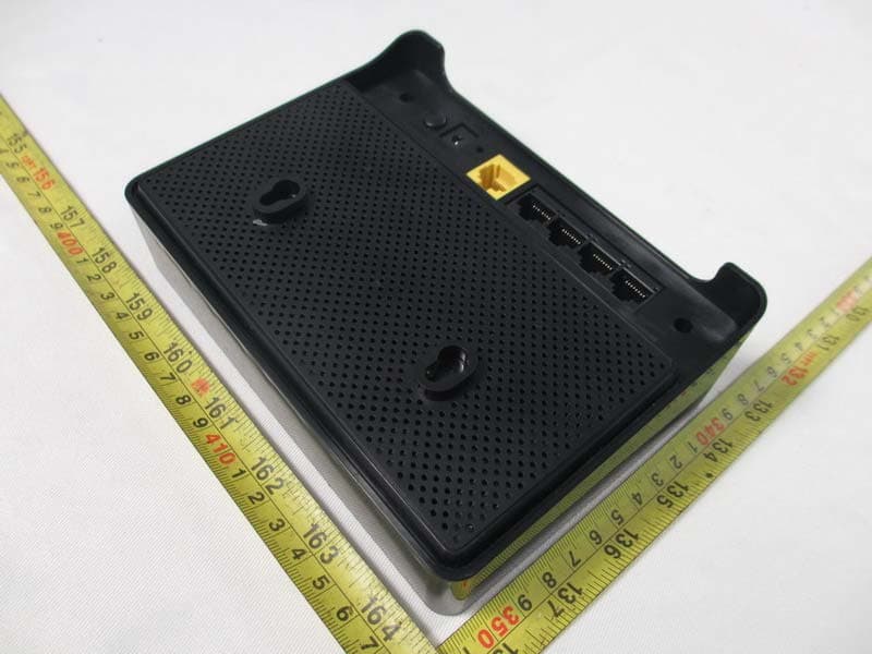
Click to zoom
Application Details
- Equipment Class
- DTS - Digital Transmission System
- Date of Grant
- Aug 19, 2013
- Application Purpose
- Original Equipment
- Date of Application
- Aug 19, 2013
- Equipment Note
- Wireless router
- Frequency Range
- 2412.00000000 - 2462.00000000
- Company
- D-Link Corporation
- Country
- United States
Documents & Files
Document Text
Text extracted from the exhibit documents filed with the FCC. Open a document above to read the original.
Users Manual
Quick Installation Guide DIR-815 Wireless router BEFORE YOU BEGIN Delivery Package •Wireless router DIR-815 •Power adapter DC 12V •Ethernet cable (CAT 5E) •“Quick Installation Guide” (brochure). If any of the items are missing, please contact your reseller. The “User Manual” and “Quick Installation Guide” documents in Russian and English are available on D-Link website (see ftp.dlink.ru/pub/Router/DIR-815/Description/RevC/). ! Using a power supply with a different voltage rating than the one included will cause damage and void the warranty for this product. Default Settings IP address of router 192.168.0.1 Username (login) admin Password admin Name of wireless network (SSID) 2.4GHz DIR-815 5GHz DIR-815-5G System Requirements and Equipment •A computer with any operating system that supports a web browser. •A web browser to access the web-based interface of the router: Windows Internet Explorer, Mozilla Firefox, or Opera. •A NIC (Ethernet or Wi-Fi adapter) to connect to the router. •An 802.11a, b, g, or n Wi-Fi adapter to create a wireless network. CONNECTION AND CONFIGURATION 1. Connect the power cord to the power connector port on the back panel of the router, then plug the power adapter into an electrical outlet or power strip. 2. Connect the router to your PC. •PC with Ethernet adapter: connect an Ethernet cable between an available Ethernet port of the router and the Ethernet port of your PC. Turn on the router by pressing the ON/OFF button on its back panel. Turn on your PC and wait until your operating system is completely loaded. •PC with Wi-Fi adapter: turn on the router by pressing the ON/OFF button on its back panel. Turn on your PC and wait until your operating system is completely loaded. Then turn on your Wi-Fi adapter and connect to the network DIR-815 (for operating in the 2.4GHz band) or DIR-815-5G (for operating in the 5GHz band). 3. Start a web browser. In the address bar of the web browser, enter the IP address of the router (by default, 192.168.0.1). Press the Enter key. 4. On the opened page, enter the username and password for the administrator account in the Login and Password fields correspondingly (by default, the following username and password are specified: admin, admin). Then click the Enter link. After the first access to the web-based interface you are forwarded to the page for changing the administrator password specified by default. Enter the new password in the Password and Confirmation fields. Then click the Save link. Remember or write down the new password for the administrator account. After successful registration the router's quick settings page opens. The web-based interface of the router is multilingual. Select a needed language from the menu displayed when the mouse pointer is over the Language caption. On the quick settings page, you can run a needed Wizard (use the links on the left side of the page), quickly get to some pages of the web-based interface, find a specific page via search, or switch to the advanced settings section (click the Advanced settings link in the bottom right corner of the page). To configure connection to the Internet, click the Click'n'Connect link in the Net section on the quick settings page or go to the advanced settings page and click the WAN link in the Net section. To change settings of the LAN, left-click the IP address of the local interface (right column of the LAN IP line on the Network information section on the quick settings page) or go to the advanced settings page and click the LAN link in the Net section. To configure the wireless network, click the Wireless network settings wizard link in the Wi-Fi section on the quick settings page or go to the advanced settings page and click the Basic settings link in the Wi-Fi section. For detailed description of every page of the web-based interface, see the “User Manual” document on D-Link website (ftp.dlink.ru/pub/Router/DIR-815/Description/RevC/). TROUBLESHOOTING Question 1. How do I reset the router to the factory default settings? You can restore the factory default settings via the hardware RESET button located on the back panel of the router. 1. Use a small paperclip to activate the button; insert it into the hole (with the device turned on), push, and hold for 7 seconds. 2. Release the button and wait until the router is rebooted (about 30 seconds). This procedure wipes out all settings that you have configured for your router. You can access the web-based interface of the router and configure all needed settings using the default IP address, username, and password (see the Connection and Configuration chapter of the present document). Question 2. What can I do if my router is not working correctly? Below are some steps applicable to the most common issues. 1. Check the LEDs on the front panel of the router. The following LEDs should be solid or blinking green: POWER, INTERNET, LAN (corresponding to the LAN ports of the router to which devices from the router's local area network are connected), 2.4GHz and 5GHz (if the 2.4GHz or 5GHz wireless network correspondingly is on and in use). 2. Make sure that all cables are connected properly. 3. Power off the router for 20 seconds, then power it on again. Question 3. Why am I unable to connect to the Internet? Contact your ISP to make sure that the relevant service is available and that you use correct connection settings. Краткое руководство по установке DIR-815 Беспроводной двухдиапазонный маршрутизатор с поддержкой 802.11n (до 600 Мбит/с) ПРЕДВАРИТЕЛЬНАЯ ПОДГОТОВКА Комплект поставки •Беспроводной маршрутизатор DIR-815, •адаптер питания постоянного тока 12B, •Ethernet-кабель (CAT 5E), •документ «Краткое руководство по установке» (буклет). Если в комплекте поставки маршрутизатора отсутствует какой-либо компонент, обратитесь к Вашему поставщику. Документы «Руководство пользователя» и «Краткое руководство по установке» на русском и английском языках доступны на сайте компании D-Link (см. ftp.dlink.ru/pub/Router/DI…
Text truncated - open the document above for the full version.
Cover Letter(s)
CERTIFICATE OF COMPLIANCE Ref No.: NEI-FCCE-1-1301C210A Date of Issue: Jul. 09, 2013 Authorized under Declaration of Conformity according to 47 CFR, Part 2 and Part 15 of the FCC Rules. The product listed in follows was (were) tested in the Neutron EMC Laboratory to comply with the criteria limits Class B of conducted and radiated emissions of the Technical Standards FCC Part 15, Subpart B, established by the FCC, USA. Equipment Wireless router Model Name DIR-815 Brand Name D-LINK Applicant D-LINK Corporation Address No.289, Sinhu 3rd Rd., Neihu District Taipei City 114, Taiwan, R.O.C Standard(s) FCC Part 15, Subpart B: 2012 ANSI C63.4 (2009) The test data, data evaluation, and equipment configuration contained in our test report (Ref No. NEI-FCCE-1-1301C210A) were obtained utilizing the test procedures, test instruments, test sites that has been accredited by the Authority of TAF according to the ISO-17025 quality assessment standard and technical standard(s). The test data contained in the referenced test report relate only to the EUT sample and item(s) tested. Andy Chiu Authorized Signatory Neutron Engineering Inc. B1, No.37, Lane 365, Yang Guang St., NeiHu District 114., Taipei, Taiwan TEL:+886-2-2657-3299 FAX:+886-2-2657-3331
External Photos
Neutron Engineering Inc. Project No.: 1301C210A Page 2 of 9 Neutron Engineering Inc. Project No.: 1301C210A Page 3 of 9 Neutron Engineering Inc. Project No.: 1301C210A Page 4 of 9 Neutron Engineering Inc. Project No.: 1301C210A Page 5 of 9
ID Label/Location Info
FCC IDKA2IR815C1 IC4216A-IR815C1
Internal Photos
Neutron Engineering Inc. Project No.: 1301C210A Page 6 of 9 Neutron Engineering Inc. Project No.: 1301C210A Page 7 of 9 Neutron Engineering Inc. Project No.: 1301C210A Page 8 of 9 Neutron Engineering Inc. Project No.: 1301C210A Page 9 of 9
RF Exposure Info
Neutron Engineering Inc. FCC RF EXPOSURE REPORT FCC ID: KA2IR815C1 Project No. : 1301C210A Equipment : Wireless router Model : DIR-815 Applicant : D-LINK Corporation Address : No.289, Sinhu 3rd Rd., Neihu District Taipei Cit y 114, Taiwan, R.O.C According: : FCC Guidelines for Human Exposure IEEE C95.05.1 Neutron Engineering Inc. No.3, Jinshagang 1st Road, ShiXia, Dalang Town, Dong Guan, China. TEL : (0769) 8318-3000 FAX : (0769) 8319-6000 Neutron Engineering Inc. MPE CALCULATION METHOD: Calculation Method of RF Safety Distance: where: S = power density P = power input to the antenna G = power gain of the antenna in the direction of interest relative to an isotropic radiator R = distance to the center of radiation of the antenna Table for Filed Antenna Table for Filed Antenna Ant. Brand Model Name Antenna TypeConnector Gain (dBi) Note 1 N2430GND Integral Antenna N/A 3 2 N2430GND Integral Antenna N/A 3 Neutron Engineering Inc. TEST RESULTS EUT: Wireless router Model Name : DIR-815 Temperature: 24 °C Relative Humidity: 60 % Pressure: 1012 hPa Test Voltage : AC 120V/60Hz Test Mode : TX B MODE CH01/CH06/CH11 Antenna Gain (dBi) Antenna Gain (numeric) Peak Output Power (dBm) Peak Output Power (mW) Power Density (S) (mW/cm 2 ) Limit of Power Density (S) (mW/cm 2 ) Te s t Result 3 1.9953 18.87 77.0903 0.030616141 Complies 3 1.9953 19.05 80.3526 0.031911731 Complies 3 1.9953 19.08 80.9096 0.032132931 Complies EUT: Wireless router Model Name : DIR-815 Temperature: 24 °C Relative Humidity: 60 % Pressure: 1012 hPa Test Voltage : AC 120V/60Hz Test Mode : TX G MODE CH01/CH06/CH11 Antenna Gain (dBi) Antenna Gain (numeric) Peak Output Power (dBm) Peak Output Power (mW) Power Density (S) (mW/cm 2 ) Limit of Power Density (S) (mW/cm 2 ) Te s t Result 3 1.9953 22.96 197.6970 0.078514591 Complies 3 1.9953 22.72 187.0682 0.074293421 Complies 3 1.9953 22.98 198.6095 0.078877001 Complies Neutron Engineering Inc. EUT: Wireless router Model Name : DIR-815 Temperature: 24 °C Relative Humidity: 60 % Pressure: 1012 hPa Test Voltage : AC 120V/60Hz Test Mode : TX N20MHz MODE CH01/CH06/CH11 Antenna Gain (dBi) Antenna Gain (numeric) Peak Output Power (dBm) Peak Output Power (mW) Power Density (S) (mW/cm 2 ) Limit of Power Density (S) (mW/cm 2 ) Te s t Result 3 1.9953 22.98 198.6095 0.078877001 Complies 3 1.9953 23.63 230.6747 0.091611581 Complies 3 1.9953 23.35 216.2719 0.085891541 Complies EUT: Wireless router Model Name : DIR-815 Temperature: 24 °C Relative Humidity: 60 % Pressure: 1012 hPa Test Voltage : AC 120V/60Hz Test Mode : TX N40MHz MODE CH03/CH06/CH09 Antenna Gain (dBi) Antenna Gain (numeric) Peak Output Power (dBm) Peak Output Power (mW) Power Density (S) (mW/cm 2 ) Limit of Power Density (S) (mW/cm 2 ) Te s t Result 3 1.9953 22.78 189.6706 0.075326951 Complies 3 1.9953 23.05 201.8366 0.080158651 Complies 3 1.9953 23.04 201.3724 0.079974291 Complies Note: the calculation distance is 20cm.
Test Report
Neutron Engineering Inc. Report No.: NEI-FCCP-1-1301C210A Page 1 of 155 FCC Radio Test Report FCC ID: KA2IR815C1 This report concerns (check one): Original Grant Class II Change Issued Date : Jul. 09, 2013 Project No. : 1301C210A Equipment : Wireless router Model Name : DIR-815 Applicant : D-LINK Corporation Address : No.289, Sinhu 3rd Rd., Neihu District Taipei City 114, Taiwan, R.O.C Tested by: Neutron Engineering Inc. EMC Laboratory Date of Receipt: May. 10, 2013 Date of Test: May. 10, 2013 ~ Jul. 08, 2013 Testing Engineer : (David Mao) Technical Manager : (Leo Hung) Authorized Signatory: (Steven Lu) Neutron Engineering Inc. No.3,Jinshagang 1st Road, ShiXia, Dalang Town, Dong Guan, China. TEL : (0769) 8318-3000 FAX : (0769) 8319-6000 Neutron Engineering Inc. Report No.: NEI-FCCP-1-1301C210A Page 2 of 155 Declaration Neutron represents to the client that testing is done in accordance with standard procedures as applicable and that test instruments used has been calibrated with the standards traceable to National Measurement Laboratory (NML) of R.O.C, or National Institute of Standards and Technology (NIST) of U.S.A. Neutron's reports apply only to the specific samples tested under conditions. It is manufacture’s responsibility to ensure that additional production units of this model are manufactured with the identical electrical and mechanical components. Neutronshall have no liability for any declarations, inferences o r generalizations drawn by the client or others from Neutron issued reports. Neutron’s reports must not be used by the client to claim product endorsement by the authorities or any agency of the Government. This report is the confidential property of the client. As a mutual protection to the clients, the public and Neutron-self, extracts from the test report shall not be reproduced except in full with Neutron’s authorized written approval. Neutron’s laboratory quality assurance procedures are in compliance with the ISO Guide 17025 requirements, and accredited by the conformity assessment authorities listed in this test report. Limitation For the use of the authority's logo is limited unless the Test Standard(s)/Scope(s)/Item(s) mentioned in this test report is (are) included in the conformity assessment authorities acceptance respective. Neutron Engineering Inc. Report No.: NEI-FCCP-1-1301C210A Page 3 of 155 Table of Contents Page 1 . CERTIFICATION 5 2 . SUMMARY OF TEST RESULTS 6 2.1 TEST FACILITY 7 2.2 MEASUREMENT UNCERTAINTY 7 3 . GENERAL INFORMATION 8 3.1 GENERAL DESCRIPTION OF EUT 8 3.2 DESCRIPTION OF TEST MODES 10 3.3 TABLE OF PARAMETERS OF TEXT SOFTWARE SETTING 11 3.4 BLOCK DIAGRAM SHOWING THE CONFIGURATION OF SYSTEM TESTED 12 3.5 DESCRIPTION OF SUPPORT UNITS 13 4 . EMC EMISSION TEST 14 4.1 CONDUCTED EMISSION MEASUREMENT 14 4.1.1 POWER LINE CONDUCTED EMISSION LIMITS 14 4.1.2 MEASUREMENT INSTRUMENTS LIST AND SETTING 14 4.1.3 TEST PROCEDURE 15 4.1.4 DEVIATION FROM TEST STANDARD 15 4.1.5 TEST SETUP 15 4.1.6 EUT OPERATING CONDITIONS 15 4.1.7 TEST RESULTS 16 4.2 RADIATED EMISSION MEASUREMENT 21 4.2.1 RADIATED EMISSION LIMITS 21 4.2.2 MEASUREMENT INSTRUMENTS LIST ANS SETTING 22 4.2.3 TEST PROCEDURE 23 4.2.4 DEVIATION FROM TEST STANDARD 23 4.2.5 TEST SETUP 24 4.2.6 EUT OPERATING CONDITIONS 25 4.2.7 TEST RESULTS (9K~ 30MHZ) 26 4.2.8 TEST RESULTS (BETWEEN 30 – 1000 MHZ) 27 4.2.9 TEST RESULTS (ABOVE 1000 MHZ) 40 5 . BANDWIDTH TEST 88 5.1 APPLIED PROCEDURES / LIMIT 88 5.1.1 MEASUREMENT INSTRUMENTS LIST 88 5.1.2 TEST PROCEDURE 88 5.1.3 DEVIATION FROM STANDARD 88 5.1.4 TEST SETUP 88 5.1.5 EUT OPERATION CONDITIONS 88 5.1.6 TEST RESULTS 89 Neutron Engineering Inc. Report No.: NEI-FCCP-1-1301C210A Page 4 of 155 Table of Contents Page 6 . MAXIMUM OUTPUT POWER TEST 101 6.1 APPLIED PROCEDURES / LIMIT 101 6.1.1 MEASUREMENT INSTRUMENTS LIST 101 6.1.2 TEST PROCEDURE 101 6.1.3 DEVIATION FROM STANDARD 101 6.1.4 TEST SETUP 101 6.1.5 EUT OPERATION CONDITIONS 101 6.1.6 TEST RESULTS 102 7 . ANTENNA CONDUCTED SPURIOUS EMISSION 105 7.1 APPLIED PROCEDURES / LIMIT 105 7.1.1 MEASUREMENT INSTRUMENTS LIST 105 7.1.2 TEST PROCEDURE 105 7.1.3 DEVIATION FROM STANDARD 105 7.1.4 TEST SETUP 105 7.1.5 EUT OPERATION CONDITIONS 105 7.1.6 TEST RESULTS 106 8 . POWER SPECTRAL DENSITY TEST 136 8.1 APPLIED PROCEDURES / LIMIT 136 8.1.1 MEASUREMENT INSTRUMENTS LIST 136 8.1.2 TEST PROCEDURE 136 8.1.3 DEVIATION FROM STANDARD 136 8.1.4 TEST SETUP 136 8.1.5 EUT OPERATION CONDITIONS 136 8.1.6 TEST RESULTS 137 9 . EUT TEST PHOTO 151 Neutron Engineering Inc. Report No.: NEI-FCCP-1-1301C210A Page 5 of 155 1. CERTIFICATION Equipment : Wireless router Brand Name : D-LINK Model Name : DIR-815 Applicant : D-LINK Corporation Manufacturer : D-LINK Corporation Address : No.289, Sinhu 3rd Rd., Neihu District Taipei City 114, Taiwan, R.O.C Factory : 1) Shenzhen Gongjin Electronics Co.,Ltd 2) TAICANG T&W Electronics Co., Ltd. Address : 1) No 2&3 Buildings, Mingwei Factory Area, Songgang Road West, No. A Building, 1#Songgang Road Songgang Sub-District, Shenzhen, Guangdong, 518105, P.R. China 2) Jiangnan Road 89, Ludu Town, Taicang, Jiangsu,215412, P.R. China Date of Test : May. 10, 2013 ~ Jul. 08, 2013 Test Item : ENGINEERING SAMPLE Standard(s) : FCC Part15, Subpart C(15.247) / ANSI C63.4-2009 The above equipment has been tested and found compliance with the requirement of the relative standards by Neutron Engineering Inc. EMC Laboratory. The test data, data evaluation, and equipment configuration contained in our test report (Ref No. NEI-FCCP-1-1301C210A) were obtained utilizing the test procedures, test instruments, test sites that has been accredited by the Authority of TAF according to the ISO-17025 quality assessment standard and technical standard(s). Neutron Engineering Inc. Report No.: NEI-FCCP-1-1301C210A Page 6 of 155 2. SUMMARY OF TEST RESULTS Test procedures according to the technical standard(s): FCC Part15 (15.247) , Subpart C Standard(s) Section Test Item Judgment Remark 15.207 Conducted Emission PASS 15.247(d) Antenna…
Text truncated - open the document above for the full version.
Test Setup Photos
Neutron Engineering Inc. Report No.: NEI-FCCP-1-1301C210A Page 151 of 155 9. EUT TEST PHOTO Conducted Measurement Photos Adapter: S06A22-120A050-PB Neutron Engineering Inc. Report No.: NEI-FCCP-1-1301C210A Page 152 of 155 Conducted Measurement Photos Adapter: F05W-120050SPAU Neutron Engineering Inc. Report No.: NEI-FCCP-1-1301C210A Page 153 of 155 Radiated Measurement Photos 9K~30MHz Neutron Engineering Inc. Report No.: NEI-FCCP-1-1301C210A Page 154 of 155 Radiated Measurement Photos 30~1000MHz Neutron Engineering Inc. Report No.: NEI-FCCP-1-1301C210A Page 155 of 155 Radiated Measurement Photos Above 1000MHz
Contact Information
Applicant
Brett Adair(General Counsel)
Test Firm
BTL Inc.Daisy Dai
Technical Specifications
| # | Rule Parts | Frequency Range | Power Output |
|---|---|---|---|
| 1 | 15C | 2.41 GHz - 2.46 GHz | 231.00 mW |
Other Applications from D-Link Corporation

KA2CS6012A1
Jul 07, 20262K Fixed Indoor Cloud Camera, 2K Fixed Indoor Wi-Fi Camera
Equipment Class
DTS - Digital Transmission SystemKA2AE65UA1
Mar 02, 2026Wi-Fi 7 BE6500 USB 3.0 Dongle
Equipment Class
NII - Unlicensed National Information Infrastructure TXKA2APE9560A1
Nov 17, 2025BE9500 Celling mount Access Point
Equipment Class
6ID - 15E 6 GHz Low Power Indoor Access PointKA2AX9UA1
Dec 04, 2024AX900 Wi-Fi 6 USB Adapter, Wi-Fi 6 AX900 USB 2.0 Dongle
Equipment Class
DSS - Part 15 Spread Spectrum TransmitterKA2AC13UA1
Dec 04, 2024AC1300 Wi-Fi 5 USB Adapter, Wi-Fi 5 AC1300 USB 2.0 Dongle
Equipment Class
DTS - Digital Transmission System