KA2IR818LA1Wireless AC750 Dual Band Gigabit Cloud Router
D-Link Corporation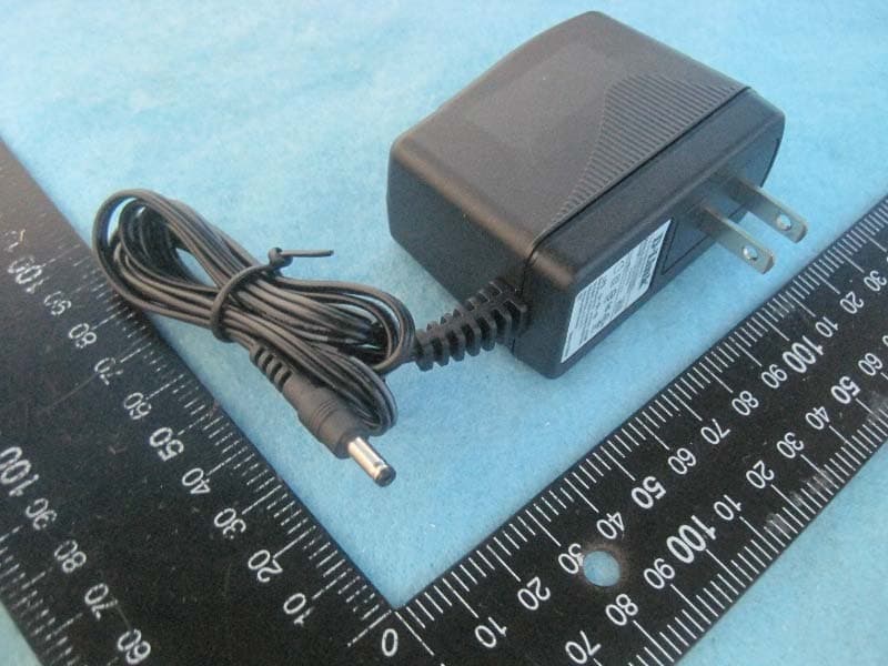
Click to zoom
Application Details
- Equipment Class
- NII - Unlicensed National Information Infrastructure TX
- Date of Grant
- Jan 07, 2014
- Application Purpose
- Original Equipment
- Date of Application
- Jan 07, 2014
- Equipment Note
- Wireless AC750 Dual Band Gigabit Cloud Router
- Frequency Range
- 5180.00000000 - 5240.00000000
- Company
- D-Link Corporation
- Country
- United States
Documents & Files
Document Text
Text extracted from the exhibit documents filed with the FCC. Open a document above to read the original.
Users Manual
ENGLISH 12V 2A WPS 1 2 3 LAN 4 INTERNET POWER USB 12V 2A WPS 1 2 3 LAN 4 INTERNET POWER USB 12V 2A WPS 1 2 3 LAN 4 INTERNET POWER USB DIR-818LW Wireless AC750 Dual Band Gigabit Router If any of the above items are missing, please contact your reseller. DIR-818L Wireless AC750 Dual Band Gigabit Router Power Adapter Ethernet Cable Wi-Fi Confi guration Card Quick Install Guide 3 5 1 Unplug the power to your DSL or Cable modem. 2 Connect an Ethernet cable from the Internet port of the router to the Ethernet port on your DSL or Cable modem. 3 Connect another Ethernet cable from the Ethernet port on your computer to one of the LAN ports on the router. 4 Plug the power back into your DSL or cable modem. Please wait about one minute before continuing. 5 Plug the power adapter into your router and connect to an available power outlet or surge protector. If the Power LED does not light up, press the Power button on the back of the router. T Modem Modem DIR-818L DIR-818L Computer Modem DIR-818L Computer Package Contents Hardware OverviewMinimum RequirementsConnect your Router 12V 2A WPS 1 2 3 LAN 4 INTERNET POWER USB 6 After the router has powered up, verify that the Power (green) and Internet (orange or green) LEDs are both lit then continue with the Confi guration section on the other side. Modem DIR-818L Computer Ethernet Port Ethernet Cable Internet Port (yellow) Ethernet Cable • Users with DSL providers - If you are using a PPPoE connection, you will need your PPPoE user name and password. If you do not have this information, contact your Internet provider. Do not proceed until you have this information. • Users with Cable providers - Make sure you unplug the power to your modem. In some cases, you may need to turn it off for up to 5 minutes. • Advanced Users - If your ISP provided you with a modem/router combo, you will need to set it to “bridge” mode so the DIR-818L router can work properly. Please contact your ISP or refer to the user manual for your modem/router device. Before you Start Network Requirements: • An Ethernet-based broadband modem Web-based Confi guration Requirements: Computer with the following: • Windows® 8, Windows® 7, Windows Vista®, Windows® XP SP3, or Mac OS® X (v10.4) • An installed Ethernet adapter or wireless adapter Supported Browsers: • Internet Explorer 7 • Safari 4 • Chrome v20.0 • Firefox v12.0 Make sure you have the latest version of Java installed. Visit www.java.com to download the latest version. mydlink Requirements: • iPhone/iPad/iPod Touch (iOS 4.3 or higher) • Android device (1.6 or higher) • Web Browser Requirements: • Internet Explorer 7 or higher • Safari 5 or higher • Chrome • Firefox Note: To learn more about mydlink, visit http://www.mydlink.com. 1 2 4 6 8 7 9 1Power LED A solid green light indicates a proper connection to the power supply. The light will be solid orange during boot-up and will blink green during the WPS process. 2Internet LED A solid light indicates a connection to the Internet port. If the LED is orange, the connection is good but the router cannot connect to the Internet. If this LED is blinking orange, this indicates that the “on demand” connection type is set and the Internet connection is idle. 3USB Port Connect a USB fl ash drive to share content throughout your network. 4WPS Button Press to start the WPS process. The Power LED will start to blink. 5LAN Ports (1-4) Connect Ethernet devices such as computers, switches, and game consoles. 6Internet Port Connect your broadband modem to this port using an Ethernet cable. 7Power ButtonPress to power the router on and off . 8Power PortConnect the supplied power adapter. 9Reset Button Press and hold the reset button with a paper clip for six seconds to reset the router to the factory default settings. ENGLISH Cable users (DHCP) click Next to continue. 4 For both the 2.4GHz and 5GHz bands, create a name for your Wi-Fi Network and a password. Your wireless devices (i.e., tablets, smartphones, and laptops) will need to have this information entered to be able to connect to your wireless network. 5 Scan the code below or search “QRS Mobile” (App Store or Google Play) to download the QRS Mobile App to your iPhone, iPad, or Android device. Once connected, click on the QRS Mobile icon from your mobile device, then click Start to continue. Please follow the on-screen instructions to complete the setup. Once the Setup Complete screen appears, click Save and write down the new Wi-Fi Network name and password on your companion card for future reference. Note: To reconnect to your router, launch your wireless utility, select the new Wi-Fi Network you created, and then enter your new Wi-Fi password. 1 3 4 Copyright ©2013 D-Link Corporation/D-Link Systems, Inc. All rights reserved. D-Link and the D-Link logo are registered trademarks of D-Link Corporation or its subsidiaries in the United States and other countries. iPhone, iPad, and iPod touch are registered trademarks of Apple Inc. Android is a trademark of Google, Inc. Other trademarks are the property of their respective owners. Maximum wireless signal rate derived from IEEE Standard 802.11ac (Draft), 802.11g, and 802.11n specifications. Actual data throughput will vary. Network conditions and environmental factors, including volume of network traffic, building materials and construction, and network overhead, lower actual data throughput rate. Environmental factors will adversely affect wireless signal range. Product specifications, size and shape are subject to change without notice, and actual product appearance may differ from that depicted on the packaging. Visit www. dlink.ca for more details. Version 1.0 | November 27, 2013 Having trouble installing your new product? D-Link’s website contains the latest user documentation and software updates for D-Link products. U.S. and Canadian customers can contact D-Link Technical Support through our website or by phone. United States Internet: http://support.dlink.com Canada Internet: http://sup…
Text truncated - open the document above for the full version.
External Photos
Report No.: 3D2018 SPORTON International Inc. PAGE NUMBER : 1 OF 5 TEL : 886-3-327-3456 ISSUED DATE : Jan. 07, 2014 FAX : 886-3-327-0973 Photographs of EUT Model No. DIR-818 (Color of housing: White) Report No.: 3D2018 SPORTON International Inc. PAGE NUMBER : 2 OF 5 TEL : 886-3-327-3456 ISSUED DATE : Jan. 07, 2014 FAX : 886-3-327-0973 Report No.: 3D2018 SPORTON International Inc. PAGE NUMBER : 3 OF 5 TEL : 886-3-327-3456 ISSUED DATE : Jan. 07, 2014 FAX : 886-3-327-0973 Model No. DIR-818L, DIR-818LW (Color of housing: Black) Report No.: 3D2018 SPORTON International Inc. PAGE NUMBER : 4 OF 5 TEL : 886-3-327-3456 ISSUED DATE : Jan. 07, 2014 FAX : 886-3-327-0973 Power Adapter Model No. AMS3-1201500FU Report No.: 3D2018 SPORTON International Inc. PAGE NUMBER : 5 OF 5 TEL : 886-3-327-3456 ISSUED DATE : Jan. 07, 2014 FAX : 886-3-327-0973
ID Label/Location Info
Label size: 42.40 x 42.40 mm
Internal Photos
Report No.: 3D2018 SPORTON International Inc. PAGE NUMBER : 1 OF 6 TEL : 886-3-327-3456 ISSUED DATE : Jan. 07, 2014 FAX : 886-3-327-0973 Photographs of EUT Report No.: 3D2018 SPORTON International Inc. PAGE NUMBER : 2 OF 6 TEL : 886-3-327-3456 ISSUED DATE : Jan. 07, 2014 FAX : 886-3-327-0973 Report No.: 3D2018 SPORTON International Inc. PAGE NUMBER : 3 OF 6 TEL : 886-3-327-3456 ISSUED DATE : Jan. 07, 2014 FAX : 886-3-327-0973 Report No.: 3D2018 SPORTON International Inc. PAGE NUMBER : 4 OF 6 TEL : 886-3-327-3456 ISSUED DATE : Jan. 07, 2014 FAX : 886-3-327-0973 Report No.: 3D2018 SPORTON International Inc. PAGE NUMBER : 5 OF 6 TEL : 886-3-327-3456 ISSUED DATE : Jan. 07, 2014 FAX : 886-3-327-0973 Report No.: 3D2018 SPORTON International Inc. PAGE NUMBER : 6 OF 6 TEL : 886-3-327-3456 ISSUED DATE : Jan. 07, 2014 FAX : 886-3-327-0973
RF Exposure Info
Report No.: FR3D2018 FCC ID: KA2IR818LA1 Page No. : B1 of B3 Appendix B. Maximum Permissible Exposure Report No.: FR3D2018 FCC ID: KA2IR818LA1 Page No. : B2 of B3 1. Maximum Permissible Exposure 1.1. Applicable Standard Systems operating under the provisions of this section shall be operated in a manner that ensures that the public is not exposed to radio frequency energy levels in excess limit for maximum permissible exposure. In accordance with 47 CFR FCC Part 2 Subpart J, section 2.1091 this device has been defined as a mobile device whereby a distance of 0.2 m normally can be maintained between the user and the device. (A) Limits for Occupational / Controlled Exposure Frequency Range (MHz) Electric Field Strength (E) (V/m) Magnetic Field Strength (H) (A/m) Power Density (S) (mW/ cm²) Averaging Time |E|²,|H|² or S (minutes) 0.3-3.0 614 1.63 (100)* 6 3.0-30 1842 / f 4.89 / f (900 / f)* 6 30-300 61.4 0.163 1.0 6 300-1500 F/300 6 1500-100,000 5 6 (B) Limits for General Population / Uncontrolled Exposure Frequency Range (MHz) Electric Field Strength (E) (V/m) Magnetic Field Strength (H) (A/m) Power Density (S) (mW/ cm²) Averaging Time |E|²,|H|² or S (minutes) 0.3-1.34 614 1.63 (100)* 30 1.34-30 824/f 2.19/f (180/f)* 30 30-300 27.5 0.073 0.2 30 300-1500 F/1500 30 1500-100,000 1.0 30 Note: f = frequency in MHz ; *Plane-wave equivalent power density 1.2. MPE Calculation Method E (V/m) = d GP30 Power Density: Pd (W/m²) = 377 2 E E = Electric field (V/m) P = Average RF output power (W) G = EUT Antenna numeric gain (numeric) d = Separation distance between radiator and human body (m) The formula can be changed to Pd = 2 377 30 d GP From the EUT RF output power, the minimum mobile separation distance, d=0.2m, as well as the gain of the used antenna, the RF power density can be obtained. Report No.: FR3D2018 FCC ID: KA2IR818LA1 Page No. : B3 of B3 1.3. Calculated Result and Limit For 5GHz UNII Band: Antenna Type : PCB Antenna Max Conducted Power for IEEE 802.11a : 16.98 dBm Antenna Gain (dBi) Antenna Gain (numeric) Average Output Power (dBm) Average Output Power (mW) Power Density (S) (mW/cm²) Limit of Power Density (S) (mW/cm²) Test Result 3.50 2.2387 16.9800 49.8884 0.022231 1 Complies For 5GHz ISM Band: Antenna Type : PCB Antenna Max Conducted Power for IEEE 802.11ac MCS0, Nss1 20MHz 20.98 dBm Antenna Gain (dBi) Antenna Gain (numeric) Average Output Power (dBm) Average Output Power (mW) Power Density (S) (mW/cm²) Limit of Power Density (S) (mW/cm²) Test Result 3.50 2.2387 20.9800 125.3141 0.055841 1 Complies For 2.4GHz Band: Antenna Type : PCB Antenna Max Conducted Power for IEEE 802.11b: 22.87 dBm Antenna Gain (dBi) Antenna Gain (numeric) Average Output Power (dBm) Average Output Power (mW) Power Density (S) (mW/cm²) Limit of Power Density (S) (mW/cm²) Test Result 2.50 1.7783 22.8671 193.5129 0.068495 1 Complies CONCULSION: Both of the WLAN 2.4GHz Band and WLAN 5GHz Band can transmit simultaneously, the formula of calculatedthe MPE is: CPD1 / LPD1 + CPD2 / LPD2 + ......etc. < 1 CPD = Calculation power density LPD = Limit of power density Therefore, the worst-case situation is 0.068495 / 1 + 0.055841 / 1 = 0.124336, which is less than “1”. This confirmed that the device comply with FCC 1.1310 MPE limit.
Test Report
Report No.: FR3D2018 FCC ID: KA2IR818LA1 Page No. : C1 of C3 Appendix C. Co-location Report No.: FR3D2018 FCC ID: KA2IR818LA1 Page No. : C2 of C3 1. Results of Radiated Emissions for Co-located Temperature 25°C Humidity 54% Test Engineer Serway Li Configurations 2.4G + 5G Horizontal Report No.: FR3D2018 FCC ID: KA2IR818LA1 Page No. : C3 of C3 Vertial
Test Report
SPORTON International Inc. No. 52, Hwa Ya 1st Rd., Hwa Ya Technology Park, Kwei-Shan Hsiang, Tao Yuan Hsien, Taiwan, R.O.C. Ph: 886-3-327-3456 / FAX: 886-3-327-0973 / www.sporton.com.tw Report Format Version: 01 FCC RADIO TEST REPORT Applicant’s company D-Link Corporation Applicant Address No.289, Sinhu 3rd Rd., Neihu District, Taipei City 114, Taiwan, R.O.C. FCC ID KA2IR818LA1 Product Name Wireless AC750 Dual Band Gigabit Cloud Router Brand Name D-Link Model No. DIR-818, DIR-818L, DIR-818LW Test Rule Part(s) 47 CFR FCC Part 15 Subpart E § 15.407 Test Freq. Range 5150 ~ 5250MHz Received Date Nov. 19, 2013 Final Test Date Dec. 31, 2013 Submission Type Original Equipment Statement Test result included is for the IEEE 802.11n and IEEE 802.11a/ac (5150 ~ 5250MHz) of the product. The test result in this report refers exclusively to the presented test model / sample. Without written approval of SPORTON International Inc., the test report shall not be reproduced except in full. The measurements and test results shown in this test report were made in accordance with the procedures and found in compliance with the limit given in ANSI C63.10-2009, 47 CFR FCC Part 15 Subpart E, KDB 789033 D01 v01r03, KDB 662911 D01 v02. The test equipment used to perform the test is calibrated and traceable to NML/ROC. Report No.: FR3D2018AB Report Format Version: 01 Page No. : i of ii FCC ID: KA2IR818LA1 Issued Date : Jan. 07, 2014 Table of Contents 1. CERTIFICATE OF COMPLIANCE ......................................................................................................................... 1 2. SUMMARY OF THE TEST RESULT .......................................................................................................................... 2 3. GENERAL INFORMATION .................................................................................................................................. 3 3.1. Product Details....................................................................................................................................................................................3 3.2. Accessories .........................................................................................................................................................................................5 3.3. Table for Filed Antenna.......................................................................................................................................................................5 3.4. Table for Carrier Frequencies .............................................................................................................................................................6 3.5. Table for Product Information .............................................................................................................................................................6 3.6. Table for Test Modes ...........................................................................................................................................................................7 3.7. Table for Testing Locations..................................................................................................................................................................8 3.8. Table for Multiple List...........................................................................................................................................................................8 3.9. Table for Supporting Units ...................................................................................................................................................................8 3.10. Table for Parameters of Test Software Setting .....................................................................................................................................9 3.11. EUT Operation during Test ...................................................................................................................................................................9 3.12. Duty Cycle ........................................................................................................................................................................................10 3.13. Test Configurations ...........................................................................................................................................................................12 4. TEST RESULT ................................................................................................................................................... 14 4.1. AC Power Line Conducted Emissions Measurement.........................................................................................................................14 4.2. 26dB Bandwidth and 99% Occupied Bandwidth Measurement......................................................................................................18 4.3. Maximum Conducted Output Power Measurement .........................................................................................................................26 4.4. Power Spectral Density Measurement ..............................................................................................................................................29 4.5. Peak Excursion Measurement ...........................................................................................................................................................35 4.6. Radiated Emissions Measurement ....................................................................................................................................................40 4.7. Band Edge Emissions Measurement .................................................................................................................................................55 4.8. Frequency Stability Measurement ..........................................................…
Text truncated - open the document above for the full version.
Test Setup Photos
Report No.: FR3D2018 FCC ID: KA2IR818LA1 Page No. : A1 of A5 Appendix A. Test Photos Report No.: FR3D2018 FCC ID: KA2IR818LA1 Page No. : A2 of A5 1. Photographs of Conducted Emissions Test Configuration FRONT VIEW REAR VIEW Report No.: FR3D2018 FCC ID: KA2IR818LA1 Page No. : A3 of A5 2. Photographs of Radiated Emissions Test Configuration Test Configuration: 9kHz ~30MHz FRONT VIEW REAR VIEW Report No.: FR3D2018 FCC ID: KA2IR818LA1 Page No. : A4 of A5 Test Configuration: 30MHz~1GHz FRONT VIEW REAR VIEW Report No.: FR3D2018 FCC ID: KA2IR818LA1 Page No. : A5 of A5 Test Configuration: Above 1GHz FRONT VIEW REAR VIEW
Contact Information
Applicant
Brett Adair(General Counsel)
Technical Contact
Sporton International Inc.Sharon Jiang
[email protected]886-3-656-9065
No.8, Lane 724, Bo-ai St. · Taiwan
Non-Technical Contact
Sporton International Inc.Sharon Jiang
[email protected]886-3-656-9065
Test Firm
SPORTON International Inc.Leo Huang
Technical Specifications
| # | Rule Parts | Frequency Range | Power Output |
|---|---|---|---|
| 1 | 15E | 5.18 GHz - 5.24 GHz | 50.00 mW |
Other Applications from D-Link Corporation

KA2CS6012A1
Jul 07, 20262K Fixed Indoor Cloud Camera, 2K Fixed Indoor Wi-Fi Camera
Equipment Class
DTS - Digital Transmission SystemKA2AE65UA1
Mar 02, 2026Wi-Fi 7 BE6500 USB 3.0 Dongle
Equipment Class
NII - Unlicensed National Information Infrastructure TXKA2APE9560A1
Nov 17, 2025BE9500 Celling mount Access Point
Equipment Class
6ID - 15E 6 GHz Low Power Indoor Access PointKA2AX9UA1
Dec 04, 2024AX900 Wi-Fi 6 USB Adapter, Wi-Fi 6 AX900 USB 2.0 Dongle
Equipment Class
DSS - Part 15 Spread Spectrum TransmitterKA2AC13UA1
Dec 04, 2024AC1300 Wi-Fi 5 USB Adapter, Wi-Fi 5 AC1300 USB 2.0 Dongle
Equipment Class
DTS - Digital Transmission System