KA2MG112AA1Wireless N300 Range Extender
D-Link Corporation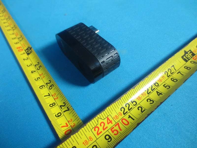
Click to zoom
Application Details
- Equipment Class
- DTS - Digital Transmission System
- Date of Grant
- Mar 15, 2015
- Application Purpose
- Original Equipment
- Date of Application
- Mar 15, 2015
- Equipment Note
- Wireless N300 Range Extender
- Frequency Range
- 2412.00000000 - 2462.00000000
- Company
- D-Link Corporation
- Country
- United States
Documents & Files
Document Text
Text extracted from the exhibit documents filed with the FCC. Open a document above to read the original.
Users Manual
Wireless N300 Range Extender DMG-112A QUICK INSTALLATION GUIDE КРАТКОЕ Р УКОВОДСТВО ПО У СТА НОВК Е GUÍA DE INSTALACIÓN RÁPIDA GUIA DE INSTALAÇÃO RÁPIDA PETUNJUK PEMASANGAN CEPAT DMG-112A 2 ENGLISH CONTENTS OF PACKAGING WIRELESS N300 RANGE EXTENDER DMG-112A If this item is missing from your package, please contact your reseller. DMG-112A D M G -112 A 3 ENGLISH INTRODUCTION The DMG-112A extends the wireless coverage of an existing AP (access point) or wireless router, allowing you to reach more parts of your home with wireless coverage. It can intuitively communicate with your router to ensure your wireless devices receive the best internet connection at all times throughout your home network. Extend the wireless coverage of another AP or wireless router. Smartphone InternetModem Computer Router DMG-112A Tablet DMG-112A DMG-112A 4 ENGLISH PRODUCT SETUP SETUP SELECT YOUR METHOD There are two methods available for setting up the DMG-112A. These are: using the D-Link One-Touch app (recommended) or Wi-Fi Protected Setup (WPS). SET UP DMG-112A WITH THE D-LINK ONE-TOUCH APP in the Apple App Store or Google Play, and download the app. Plug the DMG-112A into a 5V/1A USB power adaptor, then plug the USB power adaptor into a power outlet and wait until the blue power LED is on. NOTE : To ensure that the DMG-112A receives adequate power, please only use a 5V/1A USB power adaptor. Computer USB output of the 5V/500mA is not up to the requirements of power equipment 5V/1A, unable to make the equipment normal use, if forced to use can damage the equipment D M G -112 A 5 ENGLISH Launch the "D-Link One-Touch" app on your device and select the D-Link 112A device listed under the "Ready for Setup" section. Follow the application's prompts to complete the setup. Once you have completed the installation, the application will save a Wireless Profile Card on your device, displaying the DMG-112A’s updated information for future reference . NOTE : Please remember to store your Wireless Profile Card in a safe place on your device. PRODUCT SETUP SETUP D M G -112 A 6 ENGLISH PRODUCT SETUP SETUP SET UP DMG-112A USING Wi-Fi PROTECTED SETUP (WPS) NOTE: To connect to a wireless router or AP and extend the Wi-Fi network in your home, please make sure the source router or AP features a WPS Push Button. Push the WPS button on the source wireless router or AP, and then push the WPS button on the DMG-112A. The middle white LED on the DMG-112A will start to flash. Please allow up to two minutes for the configuration process to finish. Once configuration between the DMG-112A and the router is complete, the white LEDs will light up to indicate the strength of the signal between the DMG-112A and the router it is connected to. The DMG-112A is now connected successfully and ready to share the extended Wi-Fi network with your PCs and mobile devices. If the white LED does not turn on, you will need to repeat the WPS setup process. The SSID will be the same as the router that you are extending from. DMG-112A 7 ENGLISH TROUBLESHOOTING SETUP AND CONFIGURATION PROBLEMS 1. HOW DO I RESET MY DMG-112A WIRELESS N300 RANGE EXTENDER TO FACTORY DEFAULT SETTINGS? - Ensure the product is powered on. - Press and hold the WPS button for 6 seconds or longer until t he bottom white LED begins to Note: Resetting the product to the factory default will erase the cur settings. The default Wi-Fi network name (SSID) is dlink-112A-z with no password required. 2. HOW DO I CONNECT A PC OR OTHER DEVICE TO THE DMG-112A IF I HAVE FORGOTTEN MY WI- FI NETWORK NAME (SSID) OR WI-FI PASSWORD? - If you haven't changed the extended Wi-F i network's settings, you can use the default Wi-Fi network name (SSID) dlink-112A-z with no password required. - If you did change the network name (SSID) or Wi-F i password and you deleted the Wi-F i described in Question 1 above. D M G -112 A 8 ENGLISH TECHNICAL SUPPORT You can find software updates and user documentation on the D-Link website. Tech Support for customers in Australia: Tel: 1300-766-868 24/7 Technical Support Web: http://www.dlink. com.au E-mail: support@dlink. com.au India: Tel: +91-832-2856000 Toll Free 1800-233-0000 Web: www.dlink.co.in E-Mail: [email protected] Singapore, Thailand, Indonesia, Malaysia, Philippines, Vietnam: Singapore - www.dlink. com.sg Thailand - www.dlink.co.th Indonesia - www.dlink.co.id Malaysia - www.dlink.com.my Philippines - www.dlink. com.ph Vietnam - www.dlink.com.vn Korea: Tel : +82-2-2028-1810 Monday to Friday 9:00am to 6:00pm Web : http://d-link.co.kr E-mail : [email protected] New Zealand: Tel: 0800-900-900 24/7 Technical Support Web: http://www.dlink.co.nz E-mail: [email protected] South Africa and Sub Sahara Region: Tel: +27 12 661 2025 08600 DLINK (for South Africa only) Monday to Friday 8:30am to 9:00pm South Africa Time Web: http://www.d-link.co.za E-mail: [email protected] D-Link Middle East - Dubai, U.A.E. Plot No. S31102, Jebel Ali Free Zone South, P.O.Box 18224, Dubai, U.A.E. Tel: +971-4-8809022 Fax: +971-4-8809066 / 8809069 D M G -112 A 9 ENGLISH TECHNICAL SUPPORT Technical Support: +971-4-8809033 General Inquiries: info.me@ dlinkmea.com Tech Support: support.me@ dlinkmea.com Egypt 1, Makram Ebeid Street - City Lights Building Nasrcity - Cairo, Egypt Floor 6, office C2 Tel.: +2 02 26718375 - +2 02 26717280 Technical Support: +2 02 26738470 General Inquiries: info.eg@ dlinkmea.com Tech Support: support.eg@ dlinkmea.com Kingdom of Saudi Arabia Office # 84 , Al Khaleej Building ( Mujamathu Al-Khaleej) Opp. King Fahd Road, Olaya Riyadh - Saudi Arabia Tel: +966 1121 70008 Technical Support: +966 1121 70009 General Inquiries: info.sa@ dlinkmea.com Tech Support: support.sa@ dlinkmea.com Pakistan Islamabad Office: 61-A, Jinnah Avenue, Blue Area, Suite # 11, EBC, Saudi Pak Tower, Islamabad - Pakistan Tel.: +92-51-2800397, 2800398 Fax: +92-51-2800399 Karachi Office: D-147/1, KDA Scheme # 1, Opposite Mudassir Park, Karsaz Road, Karachi – Pakistan Phone: +92-21-34548158, 343266…
Text truncated - open the document above for the full version.
Cover Letter(s)
CERTIFICATE OF COMPLIANCE Authorized under Declaration of Conformity according to 47 CFR, Part 2 and Part 15 of the FCC Rules. The product listed in follows was (were) tested in the BTL EMC Laboratory to comply with the criteria limits Class B of conducted and radiated emissions of the Technical Standards FCC Part 15, Subpart B, established by the FCC, USA. Equipment Wireless N300 Range Extender Model Name DMG-112A Brand Name D-LINK Applicant D-LINK Corporation Address No.289, Sinhu 3rd., Neihu District,Taipei City 114,Taiwan,R.O.C Standard(s) FCC Part 15, Subpart B: 2013 ANSI C63.4-2009 Report(s) BTL-FCCE-1-1411C174 The test data, data evaluation, and equipment configuration contained in our test report(s) above was(were) obtained utilizing the test procedures, test instruments, test sites that has been accredited by the Authority of TAF according to the ISO-17025 quality assessment standard and technical standard(s). The test data contained in the referenced test report relate only to the EUT sample and item(s) tested. Andy Chiu Authorized Signatory BTL INC. B1, No. 37, Lane 365, Yang-Guang St., Nei-Hu District, Taipei City 114, Taiwan. TEL:+886-2-2657-3299 FAX:+886-2-2657-3331
Cover Letter(s)
Detail :Change product name from N300 Wireless Repeater to Wireless N300 Range Extender So LabelFCC doc letter confidentiality letter and Report need to be replaced.
External Photos
Project No.: 1411C174 Page 2 of 8 Project No.: 1411C174 Page 3 of 8 Project No.: 1411C174 Page 4 of 8
Internal Photos
Project No.: 1411C174 Page 5 of 8 Project No.: 1411C174 Page 6 of 8 Project No.: 1411C174 Page 7 of 8 Project No.: 1411C174 Page 8 of 8
RF Exposure Info
MPE Calculation Method E (V/m) = (30*P*G) 0.5 /d Power Density: Pd (W/m2) = E 2 /377 E = Electric Field (V/m) P = Peak RF output Power (W) G = EUT Antenna numeric gain (numeric) d = Separation distance between radiator and human body (m) The formula can be changed to Pd = (30*P*G) / (377*d 2 ) From the peak EUT RF output power, the minimum mobile separation distance, d=0.2m, as well as the gain of the used antenna, the RF power density can be obtained. Calculated Result and Limit(WORSE CASE IS AS BELOW) 26.09dBm@ 2452MHz Antenna Gain (Numeric) Peak Output Power (mW) Power Density (S) (mW/cm2) Limit of Power Density (S) (mW/cm2) Test Result 1.995(3dBi) 406.4( 26.09dBm) 0.16 1 Compiles
Test Report
Report No.: BTL-FCCP-1-1411C174Page 80 of 158 Orthogonal Axis : X Test Mode :TX N-40M MODE 2422MHz Vertical Report No.: BTL-FCCP-1-1411C174Page 81 of 158 Orthogonal Axis : X Test Mode :TX N-40M MODE 2422MHz Horizontal Report No.: BTL-FCCP-1-1411C174Page 82 of 158 Orthogonal Axis : X Test Mode :TX N-40M MODE 2422MHz Horizontal Report No.: BTL-FCCP-1-1411C174Page 83 of 158 Orthogonal Axis : X Test Mode :TX N-40M MODE 2437MHz Vertical Report No.: BTL-FCCP-1-1411C174Page 84 of 158 Orthogonal Axis : X Test Mode :TX N-40M MODE 2437MHz Vertical Report No.: BTL-FCCP-1-1411C174Page 85 of 158 Orthogonal Axis : X Test Mode :TX N-40M MODE 2437MHz Horizontal Report No.: BTL-FCCP-1-1411C174Page 86 of 158 Orthogonal Axis : X Test Mode :TX N-40M MODE 2437MHz Horizontal Report No.: BTL-FCCP-1-1411C174Page 87 of 158 Orthogonal Axis : X Test Mode :TX N-40M MODE 2452MHz Vertical Report No.: BTL-FCCP-1-1411C174Page 88 of 158 Orthogonal Axis : X Test Mode :TX N-40M MODE 2452MHz Vertical Report No.: BTL-FCCP-1-1411C174Page 89 of 158 Orthogonal Axis : X Test Mode :TX N-40M MODE 2452MHz Horizontal Report No.: BTL-FCCP-1-1411C174Page 90 of 158 Orthogonal Axis : X Test Mode :TX N-40M MODE 2452MHz Horizontal Report No.: BTL-FCCP-1-1411C174Page 91 of 158 ATTACHMENT E - BANDWIDTH Report No.: BTL-FCCP-1-1411C174Page 92 of 158 Test Mode : TX B Mode_CH01/06/11 6dB Bandwidth99% Occupied BWMin. Limit (MHz)(MHz)(kHz) 241210.0812.28500Complies 243710.0212.32 500Complies 246210.1512.32 500Complies Test Result Frequency (MHz) TX CH01 Report No.: BTL-FCCP-1-1411C174Page 93 of 158 TX CH06 TX CH11 Report No.: BTL-FCCP-1-1411C174Page 94 of 158 Test Mode: TX GMode_CH01/06/11 6dB Bandwidth99% Occupied BWMin. Limit (MHz)(MHz)(kHz) 241216.3716.52500Complies 243716.4316.52 500Complies 246216.4116.52 500Complies Test Result Frequency (MHz) TX CH01 Report No.: BTL-FCCP-1-1411C174Page 95 of 158 TX CH06 TX CH11 Report No.: BTL-FCCP-1-1411C174Page 96 of 158 Test Mode : TX N-20MHz Mode_CH01/06/11 6dB Bandwidth99% Occupied BWMin. Limit (MHz)(MHz)(kHz) 241217.3217.60500Complies 243717.3417.64 500Complies 246217.1217.60 500Complies Test Result Frequency (MHz) TX CH01 Report No.: BTL-FCCP-1-1411C174Page 97 of 158 TX CH06 TX CH11 Report No.: BTL-FCCP-1-1411C174Page 98 of 158 Test Mode : TX N-40MHz Mode_CH03/06/09 6dB Bandwidth99% Occupied BWMin. Limit (MHz)(MHz)(kHz) 242236.4836.24500Complies 243736.3836.24 500Complies 245236.4036.24 500Complies Test Result Frequency (MHz) TX CH03 Report No.: BTL-FCCP-1-1411C174Page 99 of 158 TX CH06 TX CH09 Report No.: BTL-FCCP-1-1411C174Page 100 of 158 ATTACHMENT F–MAXIMUM PEAK CONDUCTED OUTPUT POWER Report No.: BTL-FCCP-1-1411C174Page 101 of 158 Test Mode :TX B Mode_CH01/06/11_ANT 1 241216.590.0530.001.00Complies 243717.250.0530.001.00Complies 246216.650.0530.001.00Complies Result Frequency (MHz) Conducted Power (dBm) Conducted Power (W) Max. Limit (dBm) Max. Limit (W) Test Mode :TX B Mode_CH01/06/11_ANT 2 241217.130.0530.001.00Complies 243717.260.0530.001.00Complies 246217.350.0530.001.00Complies Frequency (MHz) Conducted Power (dBm) Conducted Power (W) Max. Limit (dBm) Max. Limit (W) Result Test Mode :TX B Mode_CH01/06/11_Total 241219.880.1030.001.00Complies 243720.270.1130.001.00Complies 246220.020.1030.001.00Complies Frequency (MHz) Conducted Power (dBm) Conducted Power (W) Max. Limit (dBm) Max. Limit (W) Result Report No.: BTL-FCCP-1-1411C174Page 102 of 158 Test Mode :TX G Mode_CH01/06/11_ANT 1 241222.500.1830.001.00Complies 243722.720.1930.001.00Complies 246222.730.1930.001.00Complies Frequency (MHz) Conducted Power (dBm) Conducted Power (W) Max. Limit (dBm) Max. Limit (W) Result Test Mode :TX G Mode_CH01/06/11_ANT 2 241222.610.1830.001.00Complies 243722.690.1930.001.00Complies 246222.540.1830.001.00Complies Frequency (MHz) Conducted Power (dBm) Conducted Power (W) Max. Limit (dBm) Max. Limit (W) Result Test Mode :TX G Mode_CH01/06/11_Total 241225.570.3630.001.00Complies 243725.720.3730.001.00Complies 246225.650.3730.001.00Complies Frequency (MHz) Conducted Power (dBm) Conducted Power (W) Max. Limit (dBm) Max. Limit (W) Result Report No.: BTL-FCCP-1-1411C174Page 103 of 158 Test Mode :TX N20 Mode_CH01/06/11_ANT 1 241223.080.2030.001.00Complies 243722.970.2030.001.00Complies 246222.660.1830.001.00Complies Max. Limit (W) Result Frequency (MHz) Conducted Power (dBm) Conducted Power (W) Max. Limit (dBm) Test Mode :TX N20 Mode_CH01/06/11_ANT 2 241222.940.2030.001.00Complies 243722.690.1930.001.00Complies 246222.620.1830.001.00Complies Frequency (MHz) Conducted Power (dBm) Conducted Power (W) Max. Limit (dBm) Max. Limit (W) Result Test Mode :TX N20 Mode_CH01/06/11_Total 241226.020.4030.001.00Complies 243725.840.3830.001.00Complies 246225.650.3730.001.00Complies Frequency (MHz) Conducted Power (dBm) Conducted Power (W) Max. Limit (dBm) Max. Limit (W) Result Report No.: BTL-FCCP-1-1411C174Page 104 of 158 Test Mode :TX N40 Mode_CH03/06/09_ANT 1 242223.120.2130.001.00Complies 243723.070.2030.001.00Complies 245223.100.2030.001.00Complies Max. Limit (W) Result Frequency (MHz) Conducted Power (dBm) Conducted Power (W) Max. Limit (dBm) Test Mode :TX N40 Mode_CH03/06/09_ANT 2 242223.030.2030.001.00Complies 243722.960.2030.001.00Complies 245223.060.2030.001.00Complies Conducted Power (dBm) Conducted Power (W) Max. Limit (dBm) Max. Limit (W) Result Frequency (MHz) Test Mode :TX N40 Mode_CH03/06/09_Total 242226.090.4130.001.00Complies 243726.030.4030.001.00Complies 245226.090.4130.001.00Complies Frequency (MHz) Conducted Power (dBm) Conducted Power (W) Max. Limit (dBm) Max. Limit (W) Result Report No.: BTL-FCCP-1-1411C174Page 105 of 158 ATTACHMENT G - ANTENNA CONDUCTED SPURIOUS EMISSION Report No.: BTL-FCCP-1-1411C174Page 106 of 158 Test Mode : TX B Mode_ANT 1 Report No.: BTL-FCCP-1-1411C174Page 107 of 158 TX B mode CH01 TX B mode CH11 Report No.: BTL-FCCP-1-1411C174Page 108 of 158 TX B mode CH01 (10 Harmonic of the frequency) TX B mode CH06 (10 Harmonic of the frequency) Report No.: BTL-FCCP-1-1411C174Page 109 of 158 TX …
Text truncated - open the document above for the full version.
Test Report
Report No.: BTL-FCCP-1-1411C174Page 1 of 158 FCC Radio Test Report FCC ID: KA2MG112AA1 This report concerns (check one):Original GrantClass II Change Project No.: 1411C174 Equipment: N300 Wireless Repeater Model Name: DMG-112A Applicant: D-LINK Corporation Address: No.289, Sinhu 3rd., Neihu District,Taipei City 114, Taiwan,R.O.C. Date of Receipt : Nov. 19, 2014 Date of Test: Nov. 19, 2014~Dec. 23, 2014 Issued Date: Dec. 24, 2014 Tested b y: BTL Inc. Testing Engineer: (David Mao) Technical Manager: (Leo Hung) Authorized Signatory: (Steven Lu) BTL INC. No.3, Jinshagang 1st Road, Shixia, Dalang Town, Dongguan, Guangdong, China. TEL: +86-769-8318-3000FAX: +86-769-8319-6000 Wireless N300 Range Extender Report No.: BTL-FCCP-1-1411C174Page 2 of 158 Declaration BTLrepresents to the client that testing is done in accordance with standard procedures as applicable and that test instruments used has been calibrated with the standards traceable to National Measuremen t Laboratory (NML)ofR.O.C, or National Institute of Standards and Technology (NIST) ofU.S.A. BTL's reports apply only to the specific samples tested under conditions. It is manufacture’s responsibilit y to ensure that additional production units of this model are manufactured with the identical electrical and mechanical components.BTLshall have no liability for any declarations, inferences or generalizations drawn by the client or others fromBTLissued reports. BTL’s reports must not be used by the client to claim product endorsement by the authorities or an y agency of the Government. This report is the confidential property of the client. As a mutual protection to the clients, the public and BTL-self, extracts from the test report shall not be reproduced except in full withBTL’s authorized written approval. BTL’s laboratory quality assurance procedures are in compliance with theISO Guide 17025requirements, and accredited by the conformity assessment authorities listed in this test report. Limitation For the use of the authority's logo is limited unless the Test Standard(s)/Scope(s)/Item(s) mentioned in this test report is (are) included in the conformity assessment authorities acceptance respective. Report No.: BTL-FCCP-1-1411C174Page 3 of 158 Table of ContentsPage 1 . CERTIFICATION 6 2 . SUMMARY OF TEST RESULTS 7 2.1 TEST FACILITY 8 2.2 MEASUREMENT UNCERTAINTY 8 3 . GENERAL INFORMATION 9 3.1 GENERAL DESCRIPTION OF EUT 9 3.2 DESCRIPTION OF TEST MODES11 3.3 TABLE OF PARAMETERS OF TEXT SOFTWARE SETTING12 3.4 BLOCK DIAGRAM SHOWING THE CONFIGURATION OF SYSTEM TESTED 13 3.5 DESCRIPTION OF SUPPORT UNITS13 4 . EMC EMISSION TEST14 4.1 CONDUCTED EMISSION MEASUREMENT14 4.1.1 POWER LINE CONDUCTED EMISSION LIMITS14 4.1.2 TEST PROCEDURE14 4.1.3 DEVIATION FROM TEST STANDARD14 4.1.4 TEST SETUP15 4.1.5 EUT OPERATING CONDITIONS15 4.1.6 EUT TEST CONDITIONS15 4.1.7 TEST RESULTS15 4.2 RADIATED EMISSION MEASUREMENT16 4.2.1 RADIATED EMISSION LIMITS16 4.2.2 TEST PROCEDURE17 4.2.3 DEVIATION FROM TEST STANDARD17 4.2.4 TEST SETUP17 4.2.5 EUT OPERATING CONDITIONS18 4.2.6 EUT TEST CONDITIONS18 4.2.7 TEST RESULTS (9KHZ TO 30MHZ)19 4.2.8 TEST RESULTS (BETWEEN 30MHZ TO 1000 MHZ)19 4.2.9 TEST RESULTS (ABOVE 1000 MHZ)19 5 . BANDWIDTH TEST20 5.1 APPLIED PROCEDURES20 5.1.1 TEST PROCEDURE20 5.1.2 DEVIATION FROM STANDARD20 5.1.3 TEST SETUP20 5.1.4 EUT OPERATION CONDITIONS20 5.1.5 EUT TEST CONDITIONS20 5.1.6 TEST RESULTS20 Report No.: BTL-FCCP-1-1411C174Page 4 of 158 Table of ContentsPage 6 . MAXIMUM PEAK CONDUCTED OUTPUT POWER TEST21 6.1 APPLIED PROCEDURES / LIMIT21 6.1.1 TEST PROCEDURE21 6.1.2 DEVIATION FROM STANDARD21 6.1.3 TEST SETUP21 6.1.4 EUT OPERATION CONDITIONS21 6.1.5 EUT TEST CONDITIONS21 6.1.6 TEST RESULTS21 7 . ANTENNA CONDUCTED SPURIOUS EMISSION22 7.1 APPLIED PROCEDURES / LIMIT22 7.1.1 TEST PROCEDURE22 7.1.2 DEVIATION FROM STANDARD22 7.1.3 TEST SETUP22 7.1.4 EUT OPERATION CONDITIONS22 7.1.5 EUT TEST CONDITIONS22 7.1.6 TEST RESULTS22 8 . POWER SPECTRAL DENSITY TEST23 8.1 APPLIED PROCEDURES / LIMIT23 8.1.1 TEST PROCEDURE23 8.1.2 DEVIATION FROM STANDARD23 8.1.3 TEST SETUP23 8.1.4 EUT OPERATION CONDITIONS23 8.1.5 EUT TEST CONDITIONS23 8.1.6 TEST RESULTS23 9 . MEASUREMENT INSTRUMENTS LIST24 10 . EUT TEST PHOTO26 ATTACHMENT A - CONDUCTED EMISSION30 ATTACHMENT B - RADIATED EMISSION (9KHZ TO 30MHZ)33 ATTACHMENT C - RADIATED EMISSION (30MHZ TO 1000MHZ)35 ATTACHMENT D - RADIATED EMISSION (ABOVE 1000MHZ)42 ATTACHMENT E - BANDWIDTH91 ATTACHMENT F–MAXIMUM PEAK CONDUCTED OUTPUT POWER100 ATTACHMENT G - ANTENNA CONDUCTED SPURIOUS EMISSION105 ATTACHMENT H - POWER SPECTRAL DENSITY138 Report No.: BTL-FCCP-1-1411C174Page 5 of 158 REPORT ISSUED HISTORY Issued No.DescriptionIssued Date BTL-FCCP-1-1411C174Original Issue.Dec. 24, 2014 Report No.: BTL-FCCP-1-1411C174Page 6 of 158 1. CERTIFICATION Equipment : N300 Wireless Repeater Brand Name : D-LINK Model Name : DMG-112A Applicant : D-LINK Corporation Manufacturer : SHENZHEN MTN ELECTRONICS CO., LTD Address : MTN Industrial Park, No. 5,9, FuTai Road, Pingxi community, Pingdi Street, Longgang District, Shenzhen Factory : SHENZHEN MTN ELECTRONICS CO., LTD Address : MTN Industrial Park, No. 5,9, FuTai Road, Pingxi community, Pingdi Street, Longgang District, Shenzhen Date of Test : Nov. 19, 2014~Dec. 23, 2014 Test Sample : ENGINEERING SAMPLE Standard(s) : FCC Part15, Subpart C: 2013 (15.247) / ANSI C63.4-2009 The above equipment has been tested and found compliance with the requirement of the relative standards by BTL Inc. The test data, data evaluation, and equipment configuration contained in our test report (Ref No. BTL-FCCP-1-1411C174) were obtained utilizing the test procedures, test instruments, test sites that has been accredited by the Authority of TAF according to the ISO-17025 quality assessment standard and technical standard(s). Wireless N300 Range Extender Report No.: BTL-FCCP-1-1411C174Page 7 of 158 2. SUMMARY OF TEST RESULTS Test procedures according to the technical standard(s): Applied Standard(s): FCC Part15 (15.247) ,…
Text truncated - open the document above for the full version.
Test Setup Photos
Report No.: BTL-FCCP-1-1411C174 Page 26 of 158 10. EUT TEST PHOTO Conducted Measurement Photos Report No.: BTL-FCCP-1-1411C174 Page 27 of 158 Radiated Measurement Photos 9KHz to 30MHz Report No.: BTL-FCCP-1-1411C174 Page 28 of 158 Radiated Measurement Photos 30MHz to 1000MHz Report No.: BTL-FCCP-1-1411C174 Page 29 of 158 Radiated Measurement Photos Above 1000MHz
Contact Information
Applicant
Brett Adair(General Counsel)
Test Firm
BTL Inc.Daisy Dai
Technical Specifications
| # | Rule Parts | Frequency Range | Power Output |
|---|---|---|---|
| 1 | 15C | 2.41 GHz - 2.46 GHz | 406.00 mW |
Other Applications from D-Link Corporation

KA2CS6012A1
Jul 07, 20262K Fixed Indoor Cloud Camera, 2K Fixed Indoor Wi-Fi Camera
Equipment Class
DTS - Digital Transmission SystemKA2AE65UA1
Mar 02, 2026Wi-Fi 7 BE6500 USB 3.0 Dongle
Equipment Class
NII - Unlicensed National Information Infrastructure TXKA2APE9560A1
Nov 17, 2025BE9500 Celling mount Access Point
Equipment Class
6ID - 15E 6 GHz Low Power Indoor Access PointKA2AX9UA1
Dec 04, 2024AX900 Wi-Fi 6 USB Adapter, Wi-Fi 6 AX900 USB 2.0 Dongle
Equipment Class
DSS - Part 15 Spread Spectrum TransmitterKA2AC13UA1
Dec 04, 2024AC1300 Wi-Fi 5 USB Adapter, Wi-Fi 5 AC1300 USB 2.0 Dongle
Equipment Class
DTS - Digital Transmission System