KA2SL2600UTIEEE802.11 B/G Access Point
D-Link Corporation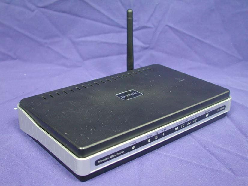
Click to zoom
Application Details
- Equipment Class
- DTS - Digital Transmission System
- Date of Grant
- Apr 01, 2007
- Application Purpose
- Original Equipment
- Date of Application
- Apr 01, 2007
- Equipment Note
- IEEE802.11 B/G Access Point
- Frequency Range
- 2412.00000000 - 2462.00000000
- Company
- D-Link Corporation
- Country
- United States
Documents & Files
Document Text
Text extracted from the exhibit documents filed with the FCC. Open a document above to read the original.
Users Manual
D-Link DSL-2640U Wireless ADSL2/2+ Ethernet Router User Manual Version 1.2 Version Date: October 12, 2006 Document #: BD-ZU0026-12 FEDERAL COMMUNICATIONS COMMISSION INTERFERENCE STATEMENT This equipment has been tested and found to comply with the limits for a Class B digital device, pursuant to part 15 of the FCC Rules. These limits are designed to provide reasonable protection against harmful interference in a residential installation. This equipment generates, uses and can radiate radio frequency energy and, if not installed and used in accordance with the instructions, may cause harmful interference to radio communications. However, there is no guarantee that interference will not occur in a particular installation. If this equipment does cause harmful interference to radio or television reception, which can be determined by turning the equipment off and on, the user is encouraged to try to correct the interference by one or more of the following measures: -Reorient or relocate the receiving antenna. -Increase the separation between the equipment and receiver. -Connect the equipment into an outlet on a circuit different from that to which the receiver is connected. -Consult the dealer or an experienced radio/ TV technician for help. This device complies with Part 15 of the FCC Rules. Operation is subject to the following two conditions: (1) This device may not cause harmful interference, and (2) this device must accept any interference received, including interference that may cause undesired operation. CAUTION: Any changes or modifications not expressly approved by the grantee of this device could void the user's authority to operate the equipment. RF exposure warning · This equipment must be installed and operated in accordance with provided instructions and the antenna(s) used for this transmitter must be installed to provide a separation distance of at least 20 cm from all persons and must not be co-located or operating in conjunction with any other antenna or transmitter. End-users and installers must be provide with antenna installation instructions and transmitter operating conditions for satisfying RF exposure compliance. D-Link Wireless ADSL2/2+ 4-port Ethernet Router 2007/3/22PM 04:50 User Manual Version 1.2 Document #: BD-ZU0026-12 1 Table of Contents . G ENERAL INFORMATION.......................................................................... 3 Package Contents ........................................................................ 3 Important Safety Instructions .......................................................... 3 Front Panel View ......................................................................... 4 Back Panel View .......................................................................... 5 C ONNECTING THE ROUTER TO YOUR COMPUTER.................................................. 6 Connect the Telephone Cable ...................................................... 6 Connect the Ethernet Cable ........................................................ 6 Connect the Power Adapter ........................................................ 6 C ONFIGURING THE ROUTER...................................................................... 7 H OME........................................................................................... 8 Wizard ..................................................................................... 8 ATM PVC Configuration........................................................... 8 Connection Type .................................................................10 PPP Username and Password ...................................................11 Network Address Translation Settings ........................................11 Device Setup ......................................................................12 Wireless............................................................................13 Setup - Summary.................................................................14 Wireless...................................................................................15 Wireless -- Basic..................................................................15 Wireless – Security ...............................................................16 WAN .......................................................................................17 LAN ........................................................................................24 DNS ........................................................................................26 DNS Server Configuration .......................................................26 Dynamic DNS .............................................................................27 Logout.....................................................................................28 A DVANCED SETUP...............................................................................30 ADSL .......................................................................................30 ADSL Settings .....................................................................31 ADSL Tone Settings ..............................................................31 Virtual Server ............................................................................32 NAT—Virtual Servers Setup .....................................................32 DMZ ........................................................................................34 SNMP ......................................................................................35 SNMP—Configuration.............................................................35 IP Filter ...................................................................................35 Incoming IP Filtering Setup .....................................................36 Outgoing IP Filtering Setup .....................................................38 Bridge Filters.............................................................................40 MAC Filtering Setu…
Text truncated - open the document above for the full version.
Users Manual
D-Link Wireless ADSL2/2+ 4-port Ethernet Router 2007/3/22PM 04:50 User Manual Version 1.2 Document #: BD-ZU0026-12 61 Wireless—Bridge In this next screen, you can select which mode you want the router to be in, either access point or wireless bridge. If you enable bridge restrict, then enter the MAC addresses of the remote bridges. If you disable the bridge restrict function, then there are no MAC addresses to enter. Click on Save / Apply to save and continue. D-Link Wireless ADSL2/2+ 4-port Ethernet Router 2007/3/22PM 04:50 User Manual Version 1.2 Document #: BD-ZU0026-12 62 Wireless—QoS WMM (Wi-Fi Multimedia) technology is available on the wireless router, allowing you to give multimedia applications a higher quality of service and priority in a wireless network so applications such as videos will be of higher quality. Enabling WMM may delay the network traffic of other lower assigned quality applications. WMM No Acknowledgement can be enabled if you enable WMM which refers to the acknowledgement policy used at the MAC level. To create a QoS entry, click the Add QoS Entry button to proceed to add or remove traffic class rules for your network. Click on Save/Apply WME Settings. D-Link Wireless ADSL2/2+ 4-port Ethernet Router 2007/3/22PM 04:50 User Manual Version 1.2 Document #: BD-ZU0026-12 63 Tools The tools section contains various administrator functions to maintain your router. Sections include the following—Admin, Time, Remote Log, System, Firmware, and Test. • Admin: Allows you to change the password for the various user names available • Time: Allows you to set the router’s time • Remote Log: Allows you to view logs of the router’s activities • System: Allows you to perform functions such as save / reboot, backup, update settings, and restore default settings • Firmware: Allows you to upgrade your router with new available firmware versions • Test: Allows you to view test information for your Internet connection Access Control You can enable or disable some services of your router by LAN or WAN. If no WAN connection is defined, only the LAN side can be configured. D-Link Wireless ADSL2/2+ 4-port Ethernet Router 2007/3/22PM 04:50 User Manual Version 1.2 Document #: BD-ZU0026-12 64 Access Control—Admin Three user names and passwords—admin, support, and user—can be used to control your router. The passwords for these user names can be changed on the following screen. Enter the user name followed by the old password and the new password that you wish to change to. D-Link Wireless ADSL2/2+ 4-port Ethernet Router 2007/3/22PM 04:50 User Manual Version 1.2 Document #: BD-ZU0026-12 65 Access Control—Services Services that can be enabled / disabled on the LAN / WAN are FTP, HTTP, ICMP, SNMP, Telnet, and TFTP. Access Control—IP Address Web access to the router can be limited when Access Control Mode is enabled. The IP addresses of allowed hosts can be added using Access Control IP Address. → Add the IP address to the IP address list by clicking on the Add button, then select “Enabled” to enable Access Control Mode. D-Link Wireless ADSL2/2+ 4-port Ethernet Router 2007/3/22PM 04:50 User Manual Version 1.2 Document #: BD-ZU0026-12 66 To assign the IP address of the management station that is permitted to access the local management services, enter the IP address in the box and click on the Apply button. D-Link Wireless ADSL2/2+ 4-port Ethernet Router 2007/3/22PM 04:50 User Manual Version 1.2 Document #: BD-ZU0026-12 67 Time The Time Settings page allows you to automatically synchronize your time with a time server on the Internet. If you choose to set the router’s time, click on the “automatically synchronize with Internet time servers” checkbox and the below fields appear. D-Link Wireless ADSL2/2+ 4-port Ethernet Router 2007/3/22PM 04:50 User Manual Version 1.2 Document #: BD-ZU0026-12 68 Select from the list of NTP (Network Time Protocol) time servers. Then select the time zone that you are in and click on Apply to save. Remote Log The Log dialog allows you to view and configure the log. To view the log, click on the View System Log button. Below is the System Log screen which shows the date/time of the log, the facility that was logged, the severity level and the log message. Click on Refresh to view any new information that is logged. D-Link Wireless ADSL2/2+ 4-port Ethernet Router 2007/3/22PM 04:50 User Manual Version 1.2 Document #: BD-ZU0026-12 69 To configure the system log settings, click on the Configure System Log button to view the following screen. NOTE: When you click on the View System Log button, the System Log screen that you access will be located under the Status section (see screen on left). To return to the previous screen to configure system log, remember to click on the Tools tab (located on top row) first and then click on Remotelog. System Log when log mode is ENABLED System Log when log mode is DISABLED D-Link Wireless ADSL2/2+ 4-port Ethernet Router 2007/3/22PM 04:50 User Manual Version 1.2 Document #: BD-ZU0026-12 70 If the log is enabled, the system will log selected events including Emergency, Alert, Critical, Error, Warning, Notice, Informational, and Debugging. All events above or equal to the selected log level will be logged and displayed. If the selected mode is “Remote” or “Both”, events will be sent to the specified IP address and UDP port of a remote system log server. If the selected mode is “Local” or “Both”, events will be recorded in the local memory. Select the desired values and click on Apply to configure the system log options. TR-069 Client The router includes a TR-069 client, a WAN management protocol. All the values are already filled in. If you wish to enable this protocol, then select enable. You must click on the Apply button for the setting to take place. D-Link Wireless ADSL2/2+ 4-port Ethernet Router 2007/3/22PM 04:50 User Manual Version 1.2 Document #: BD-ZU0026-12 71 System The system section includes several tools on one page, including…
Text truncated - open the document above for the full version.
External Photos
Report No.: 06BL040-RF-US-P05V01 Page : 1 of 10 Version:1.0 Attachment 2 : EUT Detailed Photographs (1) EUT Photo (2) EUT Photo
ID Label/Location Info
D-Link Corporation FCC ID.: KA2SL2600UT 17595 Mt.Herrmann Street , Fountain Valley, CA 92708 nited States . Tel : 886-2-66000123 # 5611 FCC ID Label The FCC ID will be placed on the equipment as shown in the photograph below.
Internal Photos
Report No.: 06BL040-RF-US-P05V01 Page : 2 of 10 Version:1.0 (3) EUT Photo (4) EUT Photo Report No.: 06BL040-RF-US-P05V01 Page : 3 of 10 Version:1.0 (5) EUT Photo (6) EUT Photo Report No.: 06BL040-RF-US-P05V01 Page : 4 of 10 Version:1.0 (7) EUT Photo (8) EUT Photo Report No.: 06BL040-RF-US-P05V01 Page : 5 of 10 Version:1.0 (9) EUT Photo (10) EUT Photo Report No.: 06BL040-RF-US-P05V01 Page : 6 of 10 Version:1.0 (11) EUT Photo (12) EUT Photo Report No.: 06BL040-RF-US-P05V01 Page : 7 of 10 Version:1.0 (13) EUT Photo (14) EUT Photo Report No.: 06BL040-RF-US-P05V01 Page : 8 of 10 Version:1.0 (15) EUT Photo (16) EUT Photo Report No.: 06BL040-RF-US-P05V01 Page : 9 of 10 Version:1.0 (17) EUT Photo (18) EUT Photo Report No.: 06BL040-RF-US-P05V01 Page : 10 of 10 Version:1.0 (19) EUT Photo
Operational Description
Report No. 06BL040-RF-US-P05V01 Page: 6 of 61 Version:1.0 1.2. Operational Description The EUT is an Wireless ADSL2/2+ Ethernet Router with a built-in 2.4GHz transceiver. There are 11 channels in 2412 – 2462MHz. The channels are separated by 5MHz. This device supports the data rates of 1, 2, 5.5, 11Mbps in 802.11b mode and 6, 9, 12, 18, 24, 36, 48, 54Mbps in 802.11g mode. The signals are modulated by DSSS in 802.11b mode and OFDM in 802.11g mode. The antenna is dipole. This Wireless ADSL2/2+ Ethernet Router, complied with IEEE 802.11b and IEEE 802.11g, is a high-efficiency Wireless ADSL router. It allows computers connecting to wired networks and Internet wirelessly and sharing network resources, such as files or printers. Wired Equivalent Protection (WEP) algorithm is used. In addition, its standard compliance ensures that it can communicate with any IEEE 802.11b and IEEE 802.11g network.
RF Exposure Info
Report No. 06BL040-RF-US-P05V01 Page: 1 of 3 Version: 1.0 RF Exposure Evaluation declaration Product Name : Wireless ADSL2/2+ Ethernet Router Model No. : DSL-2600B, DSL-2640B, DSL-2600U, DSL-2640U FCC ID KA2SL2600UT Applicant : D-Link Corporation Address : No. 289, Sinhu 3rd Road, Nei-Hu District, Taipei City, 114, Taiwan. R.O.C. Date of Receipt : Nov. 02, 2006 Date of Declaration: Dec. 11, 2006 Report No. : 06BL040-RF-US-P05V01 The declaration results relate only to the samples calculated. The declaration shall not be reproduced except in full without the written approval of QuieTek Corporation. This report must not be used to claim product endorsement by NVLAP any agency of the U.S. Government Report No. 06BL040-RF-US-P05V01 Page: 2 of 3 Version: 1.0 1. RF Exposure Evaluation 1.1. Limits According to FCC 1.1310: The criteria listed in the following table shall be used to evaluate the environment impact of human exposure to radio frequency (RF) radiation as specified in 1.1307(b) LIMITS FOR MAXIMUM PERMISSIBLE EXPOSURE (MPE) Frequency Range (MHz) Electric Field Strength (V/m) Magnetic Field Strength (A/m) Power Density (mW/cm 2 ) Average Time (Minutes) (A) Limits for Occupational/ Control Exposures 300-1500 -- -- F/300 6 1500-100,000 -- -- 5 6 (B) Limits for General Population/ Uncontrolled Exposures 300-1500 -- -- F/1500 6 1500-100,000 -- -- 1 30 F= Frequency in MHz Friis Formula Friis transmission formula: Pd = (Pout*G)/(4*pi*r 2 ) Where Pd = power density in mW/cm 2 Pout = output power to antenna in mW G = gain of antenna in linear scale Pi = 3.1416 R = distance between observation point and center of the radiator in cm Pd id the limit of MPE, 1 mW/cm 2 . If we know the maximum gain of the antenna and the total power input to the antenna, through the calculation, we will know the distance r where the MPE limit is reached. 1.2. Test Procedure Software provided by client enabled the EUT to transmit and receive data at lowest, middle and highest channel individually. The temperature and related humidity: 18°Cand 78% RH. Report No. 06BL040-RF-US-P05V01 Page: 3 of 3 Version: 1.0 1.3. Test Result of RF Exposure Evaluation Product : Wireless ADSL2/2+ Ethernet Router Test Item : RF Exposure Evaluation Test Site : No.3 OATS Antenna Gain Antenna Gain: The maximum Gain measured in fully anechoic chamber is 1.8dBi in linear scale. 802.11b Output Power Into Antenna & RF Exposure Evaluation Distance (1.8dBi): Channel Frequency (MHz) Output Power to Antenna (mW) Power Density at R = 20 cm (mW/cm2) 1 2412.00 22.4388 0.4324 6 2437.00 22.4388 0.4324 11 2462.00 23.1739 0.4466 802.11g Output Power Into Antenna & RF Exposure Evaluation Distance (1.8dBi): Channel Frequency (MHz) Output Power to Antenna (mW) Power Density at R = 20cm (mW/cm2) 1 2412.00 26.8534 0.5175 6 2437.00 25.9418 0.4999 11 2462.00 25.1768 0.4852 The distance r (4 th column) calculated from the Fries transmission formula is far shorter than 20 cm separation requirement.
Test Report
Report No. 06BL040-RF-US-P05V01 Page: 1 of 61 Version:1.0 Test Report Product Name Wireless ADSL2/2+ Ethernet Router Model No. DSL-2600B, DSL-2640B, DSL-2600U, DSL-2640U FCC ID KA2SL2600UT Applicant D-Link Corporation Address 17595 Mt.Herrmann Street , Fountain Valley, CA 92708 nited States Date of Receipt Nov. 02, 2006 Issued Date Dec. 11, 2006 Report No. 06BL040-RF-US-P05V01 The test results relate only to the samples tested. The test report shall not be reproduced except in full without the written approval of QuieTek Corporation. This report must not be used to claim product endorsement by NVLAP any agency of the U.S. Government Report No. 06BL040-RF-US-P05V01 Page: 2 of 61 Version:1.0 Test Report Certification Issued Date: Dec. 11, 2006 Report No.: 06BL040-RF-US-P05V01 Test results relate only to the samples tested. The test report shall not be reproduced except in full without the written approval of QuieTek Corporation. This report must not be used to claim product endorsement by NVLAP any agency of the U.S. Government Product Name Wireless ADSL2/2+ Ethernet Router Applicant D-Link Corporation Address 17595 Mt.Herrmann Street , Fountain Valley, CA 92708 nited States Manufacturer D-Link Corporation Model No. DSL-2600B, DSL-2640B, DSL-2600U, DSL-2640U Rated Voltage AC 120V/60Hz Working Voltage AC 120V/60Hz Trade Name D-LINK Applicable Standard FCC CFR Title 47 Part 15 Subpart C: 2005 CISPR 22: 2005 ANSI C63.4: 2003 Test Result Complied Documented By : ( Michelle Lin ) Tested By : ( Dino Chen ) Approved By : ( George Chen ) Accredited by NIST (NVLAP) NVLAP Lab Code: 200533-0 0914 Report No. 06BL040-RF-US-P05V01 Page: 3 of 61 Version:1.0 TABLE OF CONTENTS Description Page 1. GENERAL INFORMATION............................................................................................5 1.1. EUT Description.................................................................................................................5 1.2. Operational Description.......................................................................................................6 1.3. Tested System Datails..........................................................................................................7 1.4. Configuration of Test System...............................................................................................7 1.5. EUT Exercise Software........................................................................................................7 1.6. Test Facility........................................................................................................................8 2. Conducted Emission..........................................................................................................9 2.1. Test Equipment...................................................................................................................9 2.2. Test Setup...........................................................................................................................9 2.3. Limits.................................................................................................................................9 2.4. Test Procedure....................................................................................................................10 2.5. Uncertainty........................................................................................................................10 2.6. Test Result of Conducted Emission......................................................................................11 3. Peak Power Output.........................................................................................................19 3.1. Test Equipment..................................................................................................................19 3.2. Test Setup..........................................................................................................................19 3.3. Limits................................................................................................................................19 3.4. Uncertainty........................................................................................................................19 3.5. Test Result of Peak Power Output........................................................................................20 4. Radiated Emission...........................................................................................................24 4.1. Test Equipment..................................................................................................................24 4.2. Test Setup..........................................................................................................................25 4.3. Limits................................................................................................................................25 4.4. Test Procedure....................................................................................................................26 4.5. Uncertainty........................................................................................................................26 4.6. Test Result of Radiated Emission.........................................................................................27 5. Band Edge.......................................................................................................................35 5.1. Test Equipment..................................................................................................................35 5.2. Test Setup..........................................................................................................................35 5.3. Limits................................................................................................................................36 5.4. Test Procedure.......................................................................................…
Text truncated - open the document above for the full version.
Test Setup Photos
Report No.: 06BL040-RF-US-P05V01 Page : 1 of 3 Version:1.0 Attachment 1: EUT Test Setup Photographs Front View of Conducted Test Back View of Conducted Test Report No.: 06BL040-RF-US-P05V01 Page : 2 of 3 Version:1.0 Front View of Radiated Test Back View of Radiated Test Report No.: 06BL040-RF-US-P05V01 Page : 3 of 3 Version:1.0 Front View of Radiated Test (Horn) Back View of Radiated Test (Horn)
Contact Information
Applicant
Brett Adair(General Counsel)
Technical Contact
QuieTek CorporationNatasha Tai
[email protected]886 0 8792 6808
2F, No 345, Xinhu 2d Road · Taipei · Taiwan
Test Firm
DEKRA TESTING AND CERTIFICATION CO., LTD. LinKouMirenda Liao
Technical Specifications
| # | Rule Parts | Frequency Range | Power Output |
|---|---|---|---|
| 1 | 15C | 2.41 GHz - 2.46 GHz | 26.80 mW |
Other Applications from D-Link Corporation

KA2CS6012A1
Jul 07, 20262K Fixed Indoor Cloud Camera, 2K Fixed Indoor Wi-Fi Camera
Equipment Class
DTS - Digital Transmission SystemKA2AE65UA1
Mar 02, 2026Wi-Fi 7 BE6500 USB 3.0 Dongle
Equipment Class
NII - Unlicensed National Information Infrastructure TXKA2APE9560A1
Nov 17, 2025BE9500 Celling mount Access Point
Equipment Class
6ID - 15E 6 GHz Low Power Indoor Access PointKA2AX9UA1
Dec 04, 2024AX900 Wi-Fi 6 USB Adapter, Wi-Fi 6 AX900 USB 2.0 Dongle
Equipment Class
DSS - Part 15 Spread Spectrum TransmitterKA2AC13UA1
Dec 04, 2024AC1300 Wi-Fi 5 USB Adapter, Wi-Fi 5 AC1300 USB 2.0 Dongle
Equipment Class
DTS - Digital Transmission System