KA2SL2640TDIGITAL TRANSMISSION SYSTEM
D-Link Corporation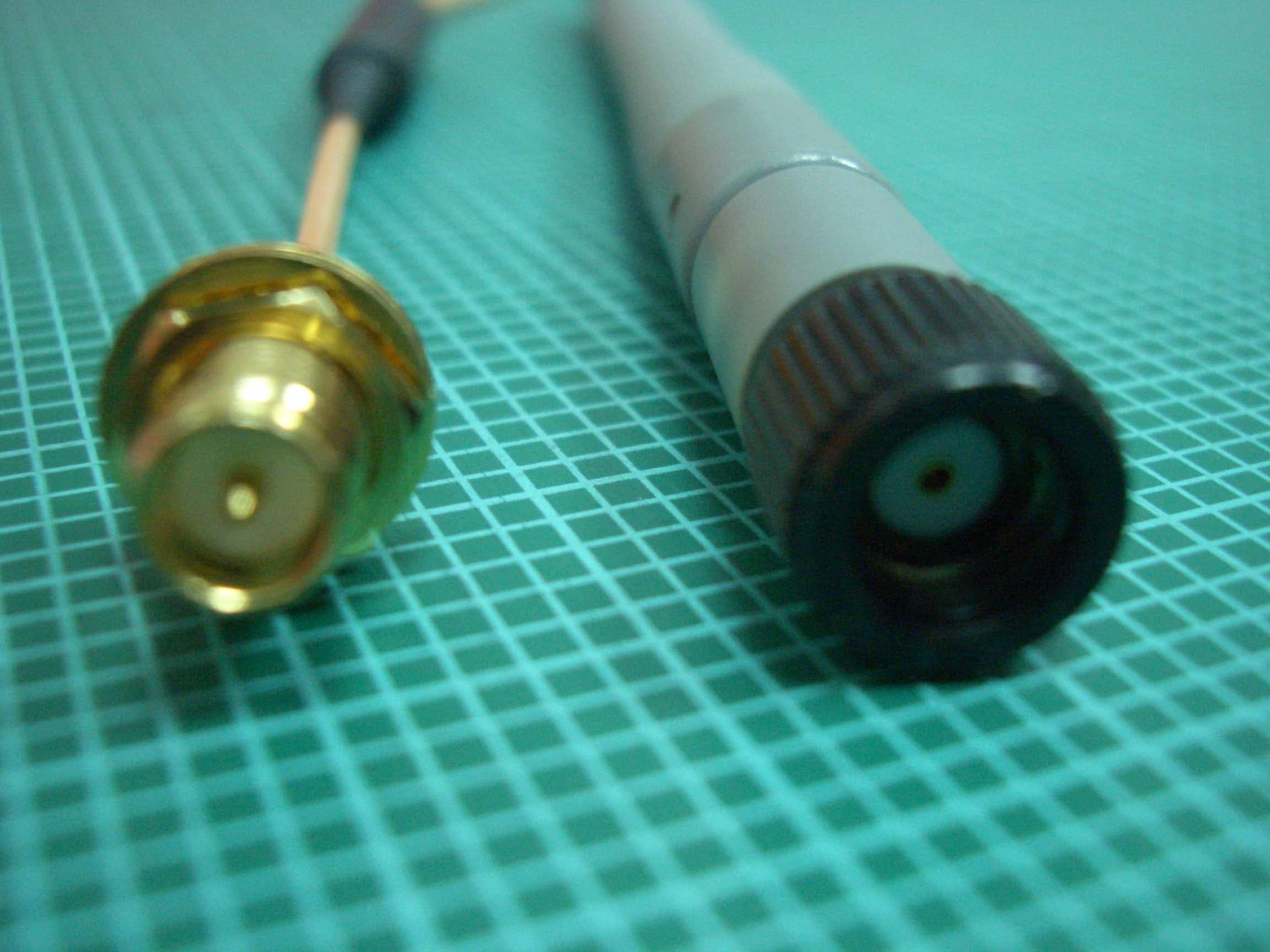
Click to zoom
Application Details
- Equipment Class
- DTS - Digital Transmission System
- Date of Grant
- Jul 05, 2006
- Application Purpose
- Original Equipment
- Date of Application
- Jul 05, 2006
- Equipment Note
- DIGITAL TRANSMISSION SYSTEM
- Frequency Range
- 2412.00000000 - 2462.00000000
- Company
- D-Link Corporation
- Country
- United States
Documents & Files
Document Text
Text extracted from the exhibit documents filed with the FCC. Open a document above to read the original.
Users Manual
Before You Begin Make sure you have all the necessary information and equipment on hand before beginning the installation. Check Your Package Contents If any of the items above are missing, please contact your reseller. This product can be set up using any current web browser, e.g., Internet Explorer 6 or Netscape Navigator 6.2.3. Using a power supply with a different voltage rating will damage and void the warranty for this product. DSL-2640T Wireless ADSL Router CD-ROM (containing Manual) Ethernet (CAT5 UTP) Cable Telephone Cable Power Adapter 2 Connecting the Router to Your Computer A. First, connect the power adapter to the receptor at the back panel of the DSL-2640T and then plug the other end of the power adapter to a wall outlet or power strip. The Power LED will turn on to indicate proper operation. B. Insert one end of the cable into the Ethernet port on the back panel of the DSL-2640T and the other end of the cable to an Ethernet Adapter or available Ethernet port on your computer. ADSL Port Connect to ADSL line Ethernet Ports Connect to Ethernet cable Power Input Connect to power adapter 3 Configuring the Router To use your Web browser to access the web pages used to set up the Router, your computer must be configured to “Obtain an IP address automatically,” that is, you must change the IP network settings of your computer so that it is a DHCP Client. If you are using Windows XP and do not know how to change your network settings, skip ahead to Appendix A and read the instructions provided. You may also read the User Manual for instructions on changing IP settings for computers running Windows operating systems. The logon pop-up screen will appear. Open your Web browser and type “http://192.168.1.1” into the URL address box. Then press the Enter or Return key. The login dialog appears. Type “admin” for the User Name and “admin” in the Password field. Click OK. 4 Configuring the Router (continued) Once you have logged in, the Home directory tab featuring the Setup Wizard window opens. Most users will be able to use the Setup Wizard to establish the ADSL connection to your ISP. To begin using the Setup Wizard, click on the Run Wizard button in the middle of the web page. The first pop-up Setup Wizard window opens. Click on the Run Wizard button. 5 Configuring the Router (continued) The Setup Wizard procedure consists of these general steps: 1. Set the time zone 2. Set the Internet connection 3. Set the Wireless configuration 4. Restart the Router When you setup the Internet connection, you will need to enter information provided by your ISP. If you have not been given information about the connection type, the VPI and VCI numbers, as well as other information related to the connection type, you will not be able to complete the setup. The first Setup Wizard window lists a summary of the steps required to complete the setup. Click the Next button to begin setup. Click the Next button. 6 Configuring the Router (continued) The initial step is to configure the Time Zone used for the Router’s system clock. Select the appropriate time zone for your location. Click the Next button when you have made your choice. Select the Time Zone. Click the Next button. 7 Configuring the Router (continued) Next you will Select the Internet Connection Type for the WAN interface. Your ISP has given this information to you. If you do not know what type of connection to use, exit the Setup Wizard and contact your ISP for the information. The Setup Wizard window that appears when you click the Next button depends on what connection type you select. The connection types available in the Setup Wizard window are PPPoE/PPPoA , Dynamic IP Address, Static IP Address, and Bridge Mode. Follow the instructions below for the type of connection you are using. Select the Connection Type used for your ADSL service. Click the Next button. 8 Configuring the Router (continued) PPPoE/PPPoA Connections If you selected the PPPoE/PPPoA connection type in the previous window, you will see the Setup Wizard window pictured here. Type in the Username and Password used to identify and verify your account to the ISP. If you have been instructed to change the VPI number and VCI number, type in the new values. Select the Connection Type used for encapsulation specific to your service. Click Next when you are ready to continue to the Setup Completed window. Type the User Name and Password for your ISP account. Change the VPI and VCI numbers as instructed by your ISP. Type the new values in the spaces provided here. Select the Connection Type as instructed by your ISP. Click the Next button. Skip ahead to the Setup Completed window below. 9 Configuring the Router (continued) Dynamic IP Address Connections If you selected the Dynamic IP Address connection type, select the Connection Type used for encapsulation. If you have been instructed to change the VPI number and VCI number, type in the new values. Click Next when you are ready to continue the Setup Completed window. Note An option for Dynamic IP Address connections is to use the MAC address from your computer in place of the Router’s actual MAC address for the purpose of Address Resolution by the ISP’s DHCP server. To implement this feature click on the Clone MAC Address button before continuing to the next window. Change the VPI and VCI numbers as instructed by your ISP. Type the new values in the spaces provided here. Select the Connection Typeas instructed by your ISP. Click the Next button. Skip ahead to the Setup Completedwindow below. 10 Configuring the Router (continued) Static IP Address Connections If you selected the Static IP Address connection type, change the WAN IP Address, Subnet Mask, ISP Gateway Address, Primary DNS (Server IP) Address and (if available) Secondary DNS (Server IP) Address as instructed by your ISP. Select the Connection Type used for encapsulation. If you have been instructed to change the VPI number and VCI number, type in the new values. Click Ne…
Text truncated - open the document above for the full version.
External Photos
Photo 1: External photo of EUT DSL-2640T Photo 2: External photo of EUT DSL-2640T Photo 3: External photo of adapter Photo 4: External photo of adapter Photo 6: External photo of antenna DSL-2640T
ID Label/Location Info
FCC ID Location 3.3 CM 6.3 CM
Internal Photos
Photo 1: Internal photo of EUT DSL-2640T Photo 2: Internal photo of EUT DSL-2640T
RF Exposure Info
FCC ID. : KA2SL2640T Report No.: EME-060497 Page 1 of 5 Maximum Permissible Exposure (MPE) Evaluation Report Report No. : EME-060497 Model No. : DSL-2640T, DSL-2540T Issued Date : Jun. 16, 2006 Applicant : D-Link Corporation No. 289, Shinhu 3 rd Rd., Neihu District, Taipei City 114, Taiwan, R.O.C. Test By : Intertek Testing Services Taiwan Ltd. No. 11, Lane 275, Ko-Nan 1 Street, Chia-Tung Li, Shiang-Shan District, Hsinchu City, Taiwan This test report consists of 5 pages in total. It may be duplicated completely for legal use with the allowance of the applicant. It shall not be reproduced except in full, without the written approval of Intertek Laboratory. The test result(s) in this report only applies to the tested sample(s). Kevin Chen Project Engineer Reviewed By Jerry Liu FCC ID. : KA2SL2640T Report No.: EME-060497 Page 2 of 5 Table of Contents Summary of Tests ............................................................................................................. 3 1. Introduction .................................................................................................................. 4 2. RF Exposure Limit ....................................................................................................... 4 3. RF Exposure calculations ............................................................................................. 5 4. Test results .................................................................................................................... 5 FCC ID. : KA2SL2640T Report No.: EME-060497 Page 3 of 5 Summary of Tests MPE Evaluation meet FCC OET No. 65: 1997/ IEEE C95.1-1999 Wireless ADSL2+ Router -Model: DSL-2640T FCC ID: KA2SL2640T Test Reference Results MPE Evaluation FCC Guidelines for Human Exposure IEEE C95.1 Pass FCC ID. : KA2SL2640T Report No.: EME-060497 Page 4 of 5 1. Introduction The EUT operates in the 2.4GHz ISM band. Due to the EUT (include antenna) at its normal operation distance is at least 20 cm from the human body, the EUT was defined as a Mobile Device. The reason to do the MPE Evaluation is to avoid the RF hazard to human body. The maximum output power and gain of the antenna were used to calculate the limited Power density (S) at 20cm distance away from the product. The limit for Maximum Permissible Exposure (MPE) specified in FCC 1.1310 is followed. According to 1.1307 (b)(1), systems operating under the provisions of this section shall be operated in a manner that ensure that the public is not exposed to radio frequency energy level in excess of the Commission’s guideline. 2. RF Exposure Limit According to FCC 1.1310: The criteria listed in the following table shall be used to evaluate the environmental impact of human exposure to radio-frequency (RF) radiation as specified in 1.1307(b). Limits for Maximum Permissible Exposure (MPE) Frequency Range (MHz) Electric Field Strength (V/m) Magnetic Field Strength (A/m) Power Density (mW/cm 2 ) Average Time (minutes) (A) Limits for Occupational / Control Exposures 30-300 61.4 0.163 1.0 6 300-1500 - - F/300 6 1500-100,000 - - 5 6 (B) Limits for General Population / Uncontrolled Exposure 30-300 27.5 0.073 0.2 30 300-1500 - - F/1500 30 1500-100,000 - - 1.0 30 F= Frequency in MHz FCC ID. : KA2SL2640T Report No.: EME-060497 Page 5 of 5 3. RF Exposure calculations From FCC 1.1310 table 1, the maximum permissible RF exposure for an uncontrolled environment is 1mW/(cm 2 ) Power density (S) is calculated by the following formula: S = (P * G)/4πR 2 where, S = Power density (mW/cm 2 ) P = Output power to antenna (mW) R = Distance between radiating structure and observation point (cm) G = Gain of antenna in numeric π = 3.1416 Example: Assume a mobile device operates at 2412MHz and its maximum output power is 50mW, and the maximum gain of antenna is 1 (numeric) /0dBi. then the power density (S) = (50 * 1)/4*π*20 2 = 0.00995 (mW/cm 2 ) 4. Test results Test Mode: 802.11b (DSSS Modulation) operating mode Channel Channel Frequency (MHz) Maximum antenna gain (numeric) Output power to antenna (mW) Power density (mW/cm 2 ) Limit of power density (mW/cm 2 ) 1 (lowest) 2412 1.58 61.940.01953 1.0 6 (middle) 2437 1.58 74.990.02364 1.0 11 (highest) 2462 1.58 57.940.18270 1.0 Test Mode: 802.11g (OFDM Modulation) operating mode Channel Channel Frequency (MHz) Maximum antenna gain (numeric) Output power to antenna (mW) Power density (mW/cm 2 ) Limit of power density (mW/cm 2 ) 1 (lowest) 2412 1.58 263.630.08312 1.0 6 (middle) 2437 1.58 325.090.10250 1.0 11 (highest) 2462 1.58 260.020.81984 1.0 The Notice in Installation Manual has been stated as below: While installing and operating this transmitter, the radio frequency exposure limit of 1mW/(cm*cm) may be exceeded at distances close to the transmitter. therefore, the user must maintain a minimum distance of 20 cm from the device at all time.
Test Report
FCC ID. : KA2SL2640T Report No.: EME-060497 Page 1 of 62 EMC TEST REPORT Report No. : EME-060497 Model No. : DSL-2640T, DSL-2540T Issued Date : Jun. 16, 2006 Applicant : D-Link Corporation No. 289, Shinhu 3 rd Rd., Neihu District, Taipei City 114, Taiwan, R.O.C. Test By : Intertek Testing Services Taiwan Ltd. No. 11, Lane 275, Ko-Nan 1 Street, Chia-Tung Li, Shiang-Shan District, Hsinchu City, Taiwan This test report consists of 62 pages in total. It may be duplicated completely for legal use with the allowance of the applicant. It shall not be reproduced except in full, without the written approval of Intertek Laboratory. The test result(s) in this report only applies to the tested sample(s). Kevin Chen Project Engineer Reviewed By Jerry Liu FCC ID. : KA2SL2640T Report No.: EME-060497 Page 2 of 62 Table of Contents Summary of Tests ..............................................................................................................4 1. General information ......................................................................................................5 1.1 Identification of the EUT ........................................................................................5 1.2 Additional information about the EUT....................................................................5 1.3 Antenna description.................................................................................................6 1.4 Peripherals equipment .............................................................................................6 2. Test specifications .........................................................................................................7 2.1 Test standard............................................................................................................7 2.2 Operation mode .......................................................................................................7 2.3 Test equipment ........................................................................................................8 3. Minimum 6dB Bandwidth test ......................................................................................9 3.1 Operating environment............................................................................................9 3.2 Test setup & procedure ............................................................................................9 3.3 Measured data of Minimum 6dB Bandwidth test results ........................................9 4. Maximum Output Power test ......................................................................................16 4.1 Operating environment..........................................................................................16 4.2 Test setup & procedure ..........................................................................................16 4.3 Measured data of Maximum Output Power test results ........................................16 5. RF Antenna Conducted Spurious test..........................................................................17 5.1 Operating environment..........................................................................................17 5.2 Test setup & procedure ..........................................................................................17 5.3 Measured data of the highest RF Antenna Conducted Spurious test result ..........17 6. Radiated Emission test ................................................................................................32 6.1 Operating environment..........................................................................................32 6.2 Test setup & procedure ..........................................................................................32 6.3 Emission limits ......................................................................................................33 6.4 Radiated spurious emission test data.....................................................................34 6.4.1 Measurement results: frequencies equal to or less than 1 GHz..........................34 6.4.2 Measurement results: frequency above 1GHz ...................................................35 7. Power Spectrum Density test ......................................................................................41 7.1 Operating environment..........................................................................................41 7.2 Test setup & procedure ..........................................................................................41 7.3 Measured data of Power Spectrum Density test results ........................................41 FCC ID. : KA2SL2640T Report No.: EME-060497 Page 3 of 62 8. Emission on the band edge..........................................................................................48 8.1 Operating environment..........................................................................................48 8.2 Test setup & procedure ..........................................................................................48 8.3 Test Result .............................................................................................................49 8.3.1 Conducted Method .............................................................................................49 8.3.2 Radiated Method ................................................................................................57 9. Power Line Conducted Emission test §FCC 15.207 ...................................................59 9.1 Operating environment..........................................................................................59 9.2 Test setup & procedure ..........................................................................................59 9.3 Emission limit .......................................................................................................60 9.4 Uncertainty of Conducted Emission ............................................…
Text truncated - open the document above for the full version.
Test Setup Photos
Photo 1: Conducted Emission Test Set-up DSL-2640T Photo 2: Conducted Emission Test Set-up DSL-2640T
Test Setup Photos
Photo 1: Radiated Emission Test Set-up DSL-2640T Photo 2: Radiated Emission Test Set-up DSL-2640T Photo 3: Radiated Emission Test Set-up DSL-2640T Photo 4: Radiated Emission Test Set-up DSL-2640T
Contact Information
Applicant
Brett Adair(General Counsel)
Test Firm
Intertek Testing Services Taiwan Ltd.Alpha Liu
Technical Specifications
| # | Rule Parts | Frequency Range | Power Output |
|---|---|---|---|
| 1 | 15C | 2.41 GHz - 2.46 GHz | 325.00 mW |
Other Applications from D-Link Corporation

KA2CS6012A1
Jul 07, 20262K Fixed Indoor Cloud Camera, 2K Fixed Indoor Wi-Fi Camera
Equipment Class
DTS - Digital Transmission SystemKA2AE65UA1
Mar 02, 2026Wi-Fi 7 BE6500 USB 3.0 Dongle
Equipment Class
NII - Unlicensed National Information Infrastructure TXKA2APE9560A1
Nov 17, 2025BE9500 Celling mount Access Point
Equipment Class
6ID - 15E 6 GHz Low Power Indoor Access PointKA2AX9UA1
Dec 04, 2024AX900 Wi-Fi 6 USB Adapter, Wi-Fi 6 AX900 USB 2.0 Dongle
Equipment Class
DSS - Part 15 Spread Spectrum TransmitterKA2AC13UA1
Dec 04, 2024AC1300 Wi-Fi 5 USB Adapter, Wi-Fi 5 AC1300 USB 2.0 Dongle
Equipment Class
DTS - Digital Transmission System