KA2SL2642BWireless ADSL Router
D-Link Corporation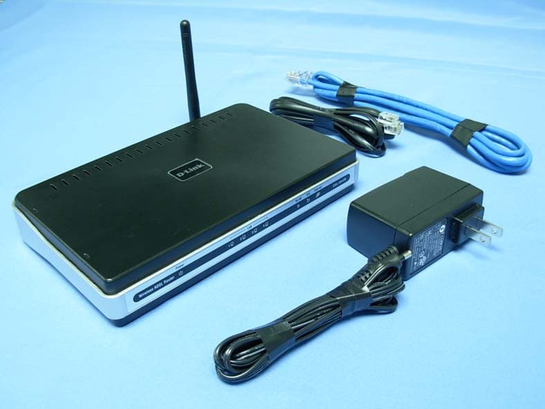
Click to zoom
Application Details
- Equipment Class
- DTS - Digital Transmission System
- Date of Grant
- Apr 06, 2008
- Application Purpose
- Original Equipment
- Date of Application
- Apr 06, 2008
- Equipment Note
- Wireless ADSL Router
- Frequency Range
- 2412.00000000 - 2462.00000000
- Company
- D-Link Corporation
- Country
- United States
Documents & Files
Document Text
Text extracted from the exhibit documents filed with the FCC. Open a document above to read the original.
Users Manual
Table of Contents 1 D-Link DSL-2642B User Manual Table of Contents TABLE OF CO NTENTS........................................................................................ 1 P ACKAGE C ONTENTS .......................................................................................... 2 S YSTEM R EQUIREMENTS ..................................................................................... 2 F EATURES .......................................................................................................... 3 H ARDWARE O VERVIEW ........................................................................................ 4 Connections ................................................................................................. 4 LEDs............................................................................................................. 5 INSTALLATION .................................................................................................... 6 B EFORE Y OU B EGIN ............................................................................................ 6 I NSTALLATION N OTES .......................................................................................... 7 D EVICE I NSTALLATION ....................................................................................... 13 Power on Ro uter ........................................................................................ 13 Factory Reset Button.................................................................................. 14 Network Con nections ................................................................................. 14 CONFIGURATION .............................................................................................. 16 W EB - BASED C ONFIGURATION U TILITY ................................................................ 16 Q UICK S ETUP ................................................................................................... 17 DEVICE INFO ..................................................................................................... 40 S UMMARY ......................................................................................................... 41 WAN................................................................................................................ 41 S TATIS TICS ....................................................................................................... 42 R OUTE ............................................................................................................. 44 ARP ................................................................................................................ 44 DHCP .............................................................................................................. 44 ADVANCED SETUP ........................................................................................... 45 WAN................................................................................................................ 45 LAN ................................................................................................................. 48 NAT ................................................................................................................. 49 Virtual Servers ............................................................................................ 49 Port Triggering ............................................................................................ 51 DMZ Host ................................................................................................... 53 S ECURITY ......................................................................................................... 53 IP Filtering .................................................................................................. 53 MAC Filtering .............................................................................................. 56 Parental Co ntrol.......................................................................................... 57 Q UALITY OF S ERVICE ......................................................................................... 59 Queue Co nfig.............................................................................................. 60 QoS Classification ...................................................................................... 61 QoS Downstream ....................................................................................... 63 R OUTING .......................................................................................................... 64 Default Ga teway ......................................................................................... 64 Static Route ................................................................................................ 64 DNS................................................................................................................. 65 DNS Server................................................................................................. 65 Dynamic DNS ............................................................................................. 66 DSL ................................................................................................................. 67 P ORT M APPING ................................................................................................. 69 PPTP ............................................................................................................... 71 WIRELESS.......................................................................................................... 72 DIAGNOSTICS ................................................................................................... 75 MANAGEME NT .................................................................................................. 76 S ETTINGS ..................................................................................................…
Text truncated - open the document above for the full version.
Users Manual
Section 3 – Configuration D-Link DSL-2642B User Manual 61 QoS Classification Choose Add or Remove to configure network traffic classes. Section 3 – Configuration D-Link DSL-2642B User Manual 62 Use this window to create a traffic cl ass rule to classify the upstream traffic, assign a queue that defines t he precedence and the interface, and optionally overwrite the IP header DSCP byte. A rule consists of a class name and at least one condition. Please re member that all of the specified conditions on this window must be me t for the rule to take effect. Click the Save/Apply button to save and activate this rule. Section 3 – Configuration D-Link DSL-2642B User Manual 63 QoS Downstream Tick Enable and enter Downstream limit in kbps to classify downstream speed. Section 3 – Configuration D-Link DSL-2642B User Manual 64 Routing To access the Routing windows, click the Routing button in the Advanced Setup directory. Default Gateway If the Enable Automatic Assigned Default Gateway checkbox is ticked, the Router will accept the first default gateway assignment received from one of the enabled PPPoA, PPPoE, or MER/DHCP enabled PVC(s). If this checkbox is not ticked, enter the static default gateway and/or a WAN interface. Click the Save/Apply button when you are finished. Static Route Click the Add button on the Routing – Static Route window to access the following window displayed on the next page. Section 3 – Configuration D-Link DSL-2642B User Manual 65 Enter the static routing information for an entry to the routing table. Click the Save/Apply button when you are finished. DNS To access the DNS windows, click the DNS button in the Advanced Setup directory. The NAT button appears when configuring WAN interface in PPPoA, PPPoE, MER or IPoA. DNS Server If you have not been given specific DNS server IP addresses or if the Router is not pre-configured with DNS server information, tick the Enable Automatic Assigned DNS checkbox. Auto discovery DNS instructs the Router to automatically obtain the DNS IP address from the ISP through DHCP. If your WAN connection uses a Static IP address, auto discovery for DNS cannot be used. If you have DNS IP addresses provided by your ISP, deselect the Enable Automatic Assigned DNS checkbox and enter these IP addresses in the available entry fields for the Prim ary DNS Server and the Secondary DNS Server. Click the Save button when you are finished. Section 3 – Configuration D-Link DSL-2642B User Manual 66 Dynamic DNS The Router supports Dynamic DNS (Dynamic Domain Name Service). The Dynamic DNS service allows a dynamic public IP address to be associated with a static host name in any of the many domains, allowing access to a specified host from various locations on the Internet. This is enabled to allow remote access to a host by clicking a hyperlinked URL in the form hostname.dyndns.org , Many ISPs assign public IP addresses using DHCP, this can make it difficult to locate a specific host on the LAN using standard DNS. If for example you ar e running a public web server or VPN server on your LAN, this ensures that the host can be located from the Internet if the public IP addr ess changes. DDNS requires that an account be setup with one of the supported DDNS providers. Click Add to see the Add DDNS Settings section. Enter the required DDNS information, click the Save/Apply button to save the information. Note DDNS requires that an account be setup with one of the supported DDNS servers prior to engaging it on the Router. This function will not work without an accepted account with a DDNS server. Section 3 – Configuration D-Link DSL-2642B User Manual 67 DSL To access the DSL Settings window, click the DSL Setup button in the Advanced Setup directory. This window allows you to select the desired modulatio n, phone line pair, and capability. Click the Save/Apply button when you are finished. Click the Advanced Settings button to select a DSL test mode. Section 3 – Configuration D-Link DSL-2642B User Manual 68 Select the desired DSL test mode and then click the Apply button. Click the Tone Selection button to modify the upstream and downstream tones. Select the appropriate upstream and downstream tones for your ADSL connection. Click the Apply button to let your settings take effect . Section 3 – Configuration D-Link DSL-2642B User Manual 69 Port Mapping To access the Port Mapping window, click the Port Mapping button in the Advanced Setup directory. Use this window to enable port mapping. Tick Enable virtual ports on and enter If you are setting up the m apping groups, click the Add button. Section 3 – Configuration D-Link DSL-2642B User Manual 70 To create a new mapping group, enter Group Name , add interfaces to Grouped Interfaces . Click Save/Apply to save the changes. Section 3 – Configuration D-Link DSL-2642B User Manual 71 PPTP To access the PPTP Setting window, click the PPTP button in the Advanced Setup directory. To set up Point-to-Point Tunnel Prot ocol, tick the Enabl e check box, enter the appropriate information in the fields offered, and then click the Save/Apply button when you are finished. Section 3 – Configuration D-Link DSL-2642B User Manual 72 Wireless To access the Wireless window, click the Wireless button in the Advanced Setup directory. Basic This page is to configure basic settings of wireless LAN. Click Enable Wireless , enter a wireless networ k name (SSID) and select a country to active the wireless LAN. You can also hide the network (Hide Access Point), isolate users (Clients Isolation). Click Save/Apply to save the settings. Security In order to protect the privacy, you can setup the wireless security. Available Network Authentication methods are Open , Shared , 802.1X , WPA , WPA-PSK , WPA2 , WPA2-PSK , Mixed WPA2/WPA and Mixed WPA2/WPA-PSK . Click Save/Apply to save the settings. Section 3 – Configuration D-Link DSL-2642B User Manual 73 MAC Filter This page can help you to allow or deny certain MAC addresses to pass through or block …
Text truncated - open the document above for the full version.
Cover Letter(s)
Declaration of Authorization We Name: D-Link Corporation Address: No.289, Sinhu 3rd Rd, Neihu District, City: Taipei 114, Country: Taiwan, R.O.C Declare that: Name Representative of agent: Gene Chang Agent Company name: QuieTek Corporation Address: 2F, No. 345, Xinhu 2nd Rd., Neihu District, City: Taipei City 114, Country: Taiwan, R.O.C. is authorized to apply for Certification of the following product(s): Product description: Wireless ADSL Router Type designation: DSL-2642B, DSL-2643B, DSL-2640U, DSL-2641U Trademark: D-Link FCC ID: KA2SL2642B on our behalf. Date: 2008/03/11 City: Taipei Signature:
Cover Letter(s)
Attestation for FCC Declaration of Conformity FCC ID: KA2SL2642B Data: Mar. 11, 2008 Please be notified that we, the undersigned, D-Link Corporation declares that the product which bears the above FCC ID is also compliant with the FCC requirements for DoC. The test report number supporting the DoC is DOCTR0001. Testing in regards to this report was done by QuieTek Corporation, located at 2F, No.345, Xinhu 2nd Rd., Neihu District,, Taipei Taiwan, which has been accredited in accordance to all of the requirements of 47CFR 2.948 (d) and (e) of the FCC rules and KDB349827. Sincerely,
External Photos
Report No: 082286R-RFUSP05V01 Page: 105 of 111 Attachement ¾ EUT Photograph (1) EUT Photo (AC-DC) (2) EUT Photo Report No: 082286R-RFUSP05V01 Page: 106 of 111 (3) EUT Photo (AC-AC) (4) EUT Photo
ID Label/Location Info
FCC ID.: KA2SL2642B FCC ID AND DoC Label The FCC ID and DoC Label will be placed on the equipment as shown in the photograph below. Wireless ADSL Router Model No.: DSL-2642B, DSL-2643B, DSL-2640U, DSL-2641U F F C C C C I I D D : : KA2SL2642B This device complies with Part 15 of the FCC Rules. Operation is subject to the following two conditions: (1) this device may not cause harmful interference and (2) this device must accept any interference received, including interference that may cause undesired operation. S/N: Made in Taiwan Trade name: D-Link Model number.: DSL-2642B, DSL-2643B, DSL-2640U, DSL-2641U
Internal Photos
Report No: 082286R-RFUSP05V01 Page: 107 of 111 (5) EUT Photo (6) EUT Photo Report No: 082286R-RFUSP05V01 Page: 108 of 111 (7) EUT Photo (8) EUT Photo Report No: 082286R-RFUSP05V01 Page: 109 of 111 (9) EUT Photo Report No: 082286R-RFUSP05V01 Page: 110 of 111 (10) EUT Photo Report No: 082286R-RFUSP05V01 Page: 111 of 111 (11) EUT Photo
RF Exposure Info
Report No. 082286R-RF-US-Exp Page: 1 of 3 RF Exposure Evaluation declaration Product Name :Wireless ADSL Router Model No. :DSL-2642B, DSL-2643B, DSL-2640U, DSL-2641U FCC ID. :KA2SL2642B Applicant : D-Link Corporation Address : No.289, Sinhu 3rd Rd., Neihu Distrct, Taipei City 114, Taiwan, R.O.C. Date of Receipt : 2008/02/25 Date of Declaration : 2008/03/12 Report No. : 082286R-RF-US-Exp Version : V1.0 The declaration results relate only to the samples calculated. The declaration shall not be reproduced except in full without the written approval of QuieTek Corporation. Report No. 082286R-RF-US-Exp Page: 2 of 3 1. RF Exposure Evaluation 1.1. Limits According to FCC 1.1310: The criteria listed in the following table shall be used to evaluate the environment impact of human exposure to radio frequency (RF) radiation as specified in 1.1307(b) LIMITS FOR MAXIMUM PERMISSIBLE EXPOSURE (MPE) Frequency Range (MHz) Electric Field Strength (V/m) Magnetic Field Strength (A/m) Power Density (mW/cm 2 ) Average Time (Minutes) (A) Limits for Occupational/ Control Exposures 300-1500 -- -- F/300 6 1500-100,000 -- -- 5 6 (B) Limits for General Population/ Uncontrolled Exposures 300-1500 -- -- F/1500 6 1500-100,000 -- -- 1 30 F= Frequency in MHz Friis Formula Friis transmission formula: Pd = (Pout*G)/(4*pi*r 2 ) Where Pd = power density in mW/cm 2 Pout = output power to antenna in mW G = gain of antenna in linear scale Pi = 3.1416 R = distance between observation point and center of the radiator in cm Pd id the limit of MPE, 1 mW/cm 2 . If we know the maximum gain of the antenna and the total power input to the antenna, through the calculation, we will know the distance r where the MPE limit is reached. 1.2. Test Procedure Software provided by client enabled the EUT to transmit and receive data at lowest, middle and highest channel individually. The temperature and related humidity: 18°Cand 78% RH. Report No. 082286R-RF-US-Exp Page: 3 of 3 1.3. Test Result of RF Exposure Evaluation Product Wireless ADSL Router Test Mode Mode 1: Transmit Test Condition RF Exposure Evaluation Antenna Gain Antenna Gain: The maximum Gain measured in fully anechoic chamber is 2dBi or 1.58 in linear scale. Output Power into Antenna & RF Exposure Evaluation Distance: IEEE 802.11b Bluetooth Function Channel Channel Frequency (MHz) Output Power to Antenna (mW) Power Density at R = 20 cm (mW/cm 2 ) 1 2412.00 52.6017 0.01659 6 2437.00 47.3151 0.01492 11 2462.00 49.6592 0.01566 IEEE 802.11g Bluetooth Function Channel Channel Frequency (MHz) Output Power to Antenna (mW) Power Density at R = 20 cm (mW/cm 2 ) 1 2412.00 111.4295 0.03513 6 2437.00 120.7814 0.03808 11 2462.00 110.9175 0.03497 The power density Pd (4th column) at a distance of 20 cm calculated from the Friis transmission formula is far below the limit of 1 mW/cm 2 .
Test Report
Report No: 082286R-RFUSP05V01 Page: 1 of 111 Test Report Product Name :Wireless ADSL Router Model No. :DSL-2642B, DSL-2643B, DSL-2640U, DSL-2641U FCC ID. :KA2SL2642B Applicant: D-Link Corporation Address : No.289, Sinhu 3rd Rd., Neihu Distrct, Taipei City 114, Taiwan, R.O.C. Date of Receipt:2008/02/25 Issued Date :2008/03/12 Report No. :082286R-RFUSP05V01 Version :V1.0 The test results relate only to the samples tested. The test report shall not be reproduced except in full without the written approval of QuieTek Corporation. Report No: 082286R-RFUSP05V01 Page: 2 of 111 Test Report Certification Issued Date : 2008/03/12 Report No. : 082286R-RFUSP05V01 Product Name : Wireless ADSL Router Applicant : D-Link Corporation Address : No.289, Sinhu 3rd Rd., Neihu Distrct, Taipei City 114, Taiwan, R.O.C. Manufacturer : Alpha Networks Inc. Model No. : DSL-2642B, DSL-2643B, DSL-2640U, DSL-2641U FCC ID. : KA2SL2640RD Rated Voltage : AC 120 V / 60 Hz EUT Voltage : AC 120 V / 60 Hz Trade Name : D-Link Applicable Standard : FCC CFR Title 47 Part 15 Subpart C Section 15.247 Test Result : Complied The test results relate only to the samples tested. The test report shall not be reproduced except in full without the written approval of QuieTek Corporation. Documented By : (Carol Tsai / Senior Engineering Adm. Specialist ) Reviewed By : ( Lucia Lu / Assistant Engineer ) Approved By : ( Roy Wang / Manager ) Report No: 082286R-RFUSP05V01 Page: 3 of 111 TABLE OF CONTENTS Description Page 1. General Information ..................................................................................................... 5 1.1. EUT Description ............................................................................................................. 5 1.2. Operational Description .................................................................................................. 7 1.3. Test Mode .......................................................................................................................8 1.4. Tested System Details .................................................................................................... 9 1.1. Configuration of Tested System ............................................................................... 10 1.5. EUT Exercise Software ................................................................................................ 11 1.6. Test Facility...................................................................................................................12 2. Conducted Emission.................................................................................................. 13 2.1. Test Equipment............................................................................................................. 13 2.2. Test Setup .................................................................................................................... 13 2.3. Limits ............................................................................................................................ 14 2.4. Test Procedure ............................................................................................................. 14 2.5. Uncertainty ................................................................................................................... 14 2.6. Test Result....................................................................................................................15 2.7. Test Photo .................................................................................................................... 31 3. Peak Power Output .................................................................................................... 33 3.1. Test Equipment............................................................................................................. 33 3.2. Test Setup .................................................................................................................... 33 3.3. Test procedures ............................................................................................................ 33 3.4. Limits ............................................................................................................................ 33 3.5. Uncertainty ................................................................................................................... 33 3.6. Test Result....................................................................................................................34 4. Radiated Emission ..................................................................................................... 42 4.1. Test Equipment............................................................................................................. 42 4.2. Test Setup .................................................................................................................... 42 4.3. Limits ............................................................................................................................ 43 4.4. Test Procedure ............................................................................................................. 43 4.5. Uncertainty ................................................................................................................... 43 4.6. Test Result....................................................................................................................44 4.7. Test Photo .................................................................................................................... 64 5. RF antenna conducted test ....................................................................................... 67 5.1. Test Equipment............................................................................................................. 67 5.2. Test Setup .................................................................................................................... 67 5.…
Text truncated - open the document above for the full version.
Test Setup Photos
Report No: 082286R-RFUSP05V01 Page: 31 of 111 2.7. Test Photo Test Mode : Mode 1: Transmit (AC-DC) Description: Front View of Conducted Emission Test Setup Test Mode : Mode 1: Transmit (AC-DC) Description: Back View of Conducted Emission Test Setup Report No: 082286R-RFUSP05V01 Page: 32 of 111 Test Mode : Mode 2: Transmit (AC-AC) Description: Front View of Conducted Emission Test Setup Test Mode : Mode 2: Transmit (AC-AC) Description: Back View of Conducted Emission Test Setup Report No: 082286R-RFUSP05V01 Page: 64 of 111 4.7. Test Photo Test Mode : Mode 1: Transmit (AC-DC) Description: Front View of Radiated Emission Test Setup (Bilog) Test Mode : Mode 1: Transmit (AC-DC) Description: Back View of Radiated Emission Test Setup (Bilog) Report No: 082286R-RFUSP05V01 Page: 65 of 111 Test Mode : Mode 2: Transmit (AC-AC) Description: Front View of Radiated Emission Test Setup (Bilog) Test Mode : Mode 2: Transmit (AC-AC) Description: Back View of Radiated Emission Test Setup (Bilog) Report No: 082286R-RFUSP05V01 Page: 66 of 111 Test Mode : Mode 1: Transmit (AC-DC) Description: Front View of Radiated Emission Test Setup (Horn)
Contact Information
Applicant
Brett Adair(General Counsel)
Technical Contact
Qui Tek Corp.Emily Chen
[email protected]886-2-8792-6808
2F No. 345, Xinhu 2nd Rd. Neihu District · Taipei · Taiwan
Test Firm
DEKRA TESTING AND CERTIFICATION CO., LTD. LinKouMirenda Liao
Technical Specifications
| # | Rule Parts | Frequency Range | Power Output |
|---|---|---|---|
| 1 | 15C | 2.41 GHz - 2.46 GHz | 121.00 mW |
Other Applications from D-Link Corporation

KA2CS6012A1
Jul 07, 20262K Fixed Indoor Cloud Camera, 2K Fixed Indoor Wi-Fi Camera
Equipment Class
DTS - Digital Transmission SystemKA2AE65UA1
Mar 02, 2026Wi-Fi 7 BE6500 USB 3.0 Dongle
Equipment Class
NII - Unlicensed National Information Infrastructure TXKA2APE9560A1
Nov 17, 2025BE9500 Celling mount Access Point
Equipment Class
6ID - 15E 6 GHz Low Power Indoor Access PointKA2AX9UA1
Dec 04, 2024AX900 Wi-Fi 6 USB Adapter, Wi-Fi 6 AX900 USB 2.0 Dongle
Equipment Class
DSS - Part 15 Spread Spectrum TransmitterKA2AC13UA1
Dec 04, 2024AC1300 Wi-Fi 5 USB Adapter, Wi-Fi 5 AC1300 USB 2.0 Dongle
Equipment Class
DTS - Digital Transmission System