KA2SM380A1Boxee Box
D-Link Corporation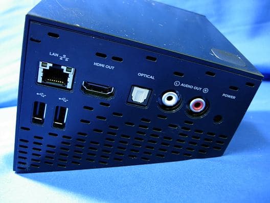
Click to zoom
Application Details
- Equipment Class
- DXT - Part 15 Low Power Transceiver, Rx Verified
- Date of Grant
- Sep 23, 2010
- Application Purpose
- Original Equipment
- Date of Application
- Sep 23, 2010
- Equipment Note
- Boxee Box
- Frequency Range
- 2402.00000000 - 2480.00000000
- Company
- D-Link Corporation
- Country
- United States
Documents & Files
Document Text
Text extracted from the exhibit documents filed with the FCC. Open a document above to read the original.
Users Manual
CE Mark Warning: This is a Class B product. In a domestic environment, this product may cause radio interference, in which case the user may be required to take adequate measures. FCC Statement: This equipment has been tested and found to comply with the limits for a Class B digital device, pursuant to part 15 of the FCC Rules. These limits are designed to provide reasonable protection against harmful interference in a residential installation. This equipment generates, uses, and can radiate radio frequency energy and, if not installed and used in accordance with the instructions, may cause harmful interference to radio communication. However, there is no guarantee that interference will not occur in a particular installation. If this equipment does cause harmful interference to radio or television reception, which can be determined by turning the equipment off and on, the user is encouraged to try to correct the interference by one or more of the following measures: • Reorient or relocate the receiving antenna. • Increase the separation between the equipment and receiver. • Connect the equipment into an outlet on a circuit different from that to which the receiver is connected. • Consult the dealer or an experienced radio/TV technician for help. FCC Caution: Any changes or modifications not expressly approved by the party responsible for compliance could void the user’s authority to operate this equipment. This device complies with Part 15 of the FCC Rules. Operation is subject to the following two conditions: (1) This device may not cause harmful interference, and (2) this device must accept any interference received, including interference that may cause undesired operation. IMPORTANT NOTICE: FCC Radiation Exposure Statement: This equipment complies with FCC radiation exposure limits set forth for an uncontrolled environment. This equipment should be installed and operated with minimum distance 20cm between the radiator & your body. This transmitter must not be co-located or operating in conjunction with any other antenna or transmitter. The availability of some specific channels and/or operational frequency bands are country dependent and are firmware programmed at the factory to match the intended destination. The firmware setting is not accessible by the end user. For detailed warranty information applicable to products purchased outside the United States, please contact the corresponding local D-Link office. Industry Canada Notice: This device complies with RSS-210 of the Industry Canada Rules. Operation is subject to the following two conditions: (1) This device may not cause harmful interference, and (2) this device must accept any interference received, including interference that may cause undesired operation. IMPORTANT NOTE: Radiation Exposure Statement: This equipment complies with IC radiation exposure limits set forth for an uncontrolled environment. This equipment should be installed and operated with minimum distance 20cm between the radiator & your body. This device has been designed to operate with an antenna having a maximum gain of 2dB. Antenna having a higher gain is strictly prohibited per regulations of Industry Canada. The required antenna impedance is 50 ohms.
External Photos
Report No.: 108137R-RFUSP42V01 Page : 1 of 11 Attachment 2 : EUT Detailed Photographs (1) EUT Photo (2) EUT Photo Report No.: 108137R-RFUSP42V01 Page : 2 of 11 (3) EUT Photo (4) EUT Photo
ID Label/Location Info
D-Link Corporation FCC ID.: KA2SM380A1 17595 Mt. Herrmann, Fountain Valley, California, United States..Tel : 714-885-6105 FCC ID Label The FCC ID and DoC Label will be placed on the equipment as shown in the photograph below.
ID Label/Location Info
D-Link Corporation FCC ID.: KA2SM380A1 17595 Mt. Herrmann, Fountain Valley, California, United States..Tel : 714-885-6105 FCC ID Label The FCC ID and DoC Label will be placed on the equipment as shown in the photograph below.
Internal Photos
Report No.: 108137R-RFUSP42V01 Page : 3 of 11 (5) EUT Photo (6) EUT Photo Report No.: 108137R-RFUSP42V01 Page : 4 of 11 (7) EUT Photo (8) EUT Photo Report No.: 108137R-RFUSP42V01 Page : 5 of 11 (9) EUT Photo (10) EUT Photo Report No.: 108137R-RFUSP42V01 Page : 6 of 11 (11) EUT Photo (12) EUT Photo Report No.: 108137R-RFUSP42V01 Page : 7 of 11 (13) EUT Photo (14) EUT Photo Report No.: 108137R-RFUSP42V01 Page : 8 of 11 (15) EUT Photo (16) EUT Photo Report No.: 108137R-RFUSP42V01 Page : 9 of 11 (17) EUT Photo (18) EUT Photo Antenna WLAN Aux Antenna WLAN Main Antenna Report No.: 108137R-RFUSP42V01 Page : 10 of 11 (19) EUT Photo (20) EUT Photo Report No.: 108137R-RFUSP42V01 Page : 11 of 11 (21) EUT Photo
Operational Description
Report No. 108137R-RFUSP42V01 Page: 5 of 43 1.2. Operational Description The EUT is Boxee Box built-in 2.4GHz transceiver. The operation frequency is from 2402 MHz to 2480MHz with GFSK modulation. The signal will be transmitted through 2.4 GHz RF signal from the Printed on PCB antenna. The assistant remote control can control device via 2.4GHz GFSK transceiver. AC 100-240V, 50-60Hz shall be provided for EUT operation. Test Mode Mode 1: Transmit
Test Report
Report No. 108137R-RFUSP42V01 Page: 1 of 43 Test Report Product Name Boxee Box Model No. DSM-380, DSM-380A1 FCC ID KA2SM380A1 Applicant D-Link Corporation Address No. 289, Shihu 3rd Rd., Neihu District, Taipei City 114, Taiwan, R.O.C. Date of Receipt Sep. 02, 2010 Issued Date Sep. 21, 2010 Report No. 108137R-RFUSP42V01 Report Version V1.0 The test results relate only to the samples tested. The test report shall not be reproduced except in full without the written approval of QuieTek Corporation. This report must not be used to claim product endorsement by NVLAP any agency of the U.S. Government Report No. 108137R-RFUSP42V01 Page: 2 of 43 Test Report Certification Issued Date: Sep. 21, 2010 Report No.: 108137R-RFUSP42V01 Test results relate only to the samples tested. The test report shall not be reproduced except in full without the written approval of QuieTek Corporation. This report must not be used to claim product endorsement by NVLAP any agency of the U.S. Government Product Name Boxee Box Applicant D-Link Corporation Address No. 289, Shihu 3rd Rd., Neihu District, Taipei City 114, Taiwan, R.O.C. Manufacturer TATUNG CO. Model No. DSM-380, DSM-380A1 EUT Rated Voltage AC 100-240V, 50-60Hz EUT Test Voltage AC 120V/60Hz Trade Name D-Link Applicable Standard FCC CFR Title 47 Part 15 Subpart C: 2009 ANSI C63.4: 2003 Test Result Complied Documented By : ( Senior Adm. Specialist / Rita Huang ) Tested By : ( Engineer / Vincent Chu ) Approved By : ( Manager / Vincent Lin) Report No. 108137R-RFUSP42V01 Page: 3 of 43 TABLE OF CONTENTS Description Page 1. GENERAL INFORMATION .....................................................................................................4 1.1. EUT Description............................................................................................................................4 1.2. Operational Description ................................................................................................................5 1.3. Tested System Datails....................................................................................................................6 1.4. Configuration of Test System ........................................................................................................7 1.5. EUT Exercise Software .................................................................................................................7 1.6. Test Facility ...................................................................................................................................8 2. Conducted Emission....................................................................................................................9 2.1. Test Equipment..............................................................................................................................9 2.2. Test Setup ......................................................................................................................................9 2.3. Limits ............................................................................................................................................9 2.4. Test Procedure .............................................................................................................................10 2.5. Uncertainty ..................................................................................................................................10 2.6. Test Result of Conducted Emission.............................................................................................11 3. Radiated Emission .....................................................................................................................13 3.1. Test Equipment............................................................................................................................13 3.2. Test Setup ....................................................................................................................................14 3.3. Limits ..........................................................................................................................................15 3.4. Test Procedure .............................................................................................................................15 3.5. Uncertainty ..................................................................................................................................16 3.6. Test Result of Radiated Emission................................................................................................17 4. Band Edge ..................................................................................................................................31 4.1. Test Equipment............................................................................................................................31 4.2. Test Setup ....................................................................................................................................32 4.3. Limits ..........................................................................................................................................33 4.4. Test Procedure .............................................................................................................................33 4.5. Uncertainty ..................................................................................................................................33 4.6. Test Result of Band Edge ............................................................................................................34 5. Duty Cycle ..................................................................................................................................38 5.1. Test Equipment............................................................................................................................38 5.2. Test Setup ...........................................…
Text truncated - open the document above for the full version.
Test Setup Photos
Report No.: 108137R-RFUSP42V01 Page : 1 of 3 Attachment 1: EUT Test Setup Photographs Front View of Conducted Test Back View of Conducted Test Report No.: 108137R-RFUSP42V01 Page : 2 of 3 Front View of Radiated Test Back View of Radiated Test Report No.: 108137R-RFUSP42V01 Page : 3 of 3 Front View of Radiated Test (Horn) Back View of Radiated Test (Horn)
Contact Information
Applicant
Brett Adair(General Counsel)
Technical Contact
QuieTek CorporationSabina Chen
[email protected]886-2-8601-3788
No. 5-22, Ruei-Shu Valley, Ruei-Ping Tsuen, Lin- · Taipei County · Taiwan
Test Firm
Quietek Linkou EMC LabotortyJames Chang
Technical Specifications
| # | Rule Parts | Frequency Range | Power Output |
|---|---|---|---|
| 1 | 15C | 2.40 GHz - 2.48 GHz | - |
Other Applications from D-Link Corporation

KA2CS6012A1
Jul 07, 20262K Fixed Indoor Cloud Camera, 2K Fixed Indoor Wi-Fi Camera
Equipment Class
DTS - Digital Transmission SystemKA2AE65UA1
Mar 02, 2026Wi-Fi 7 BE6500 USB 3.0 Dongle
Equipment Class
NII - Unlicensed National Information Infrastructure TXKA2APE9560A1
Nov 17, 2025BE9500 Celling mount Access Point
Equipment Class
6ID - 15E 6 GHz Low Power Indoor Access PointKA2AX9UA1
Dec 04, 2024AX900 Wi-Fi 6 USB Adapter, Wi-Fi 6 AX900 USB 2.0 Dongle
Equipment Class
DSS - Part 15 Spread Spectrum TransmitterKA2AC13UA1
Dec 04, 2024AC1300 Wi-Fi 5 USB Adapter, Wi-Fi 5 AC1300 USB 2.0 Dongle
Equipment Class
DTS - Digital Transmission System