KA2SR250NA1Wireless N Service Router
D-Link Corporation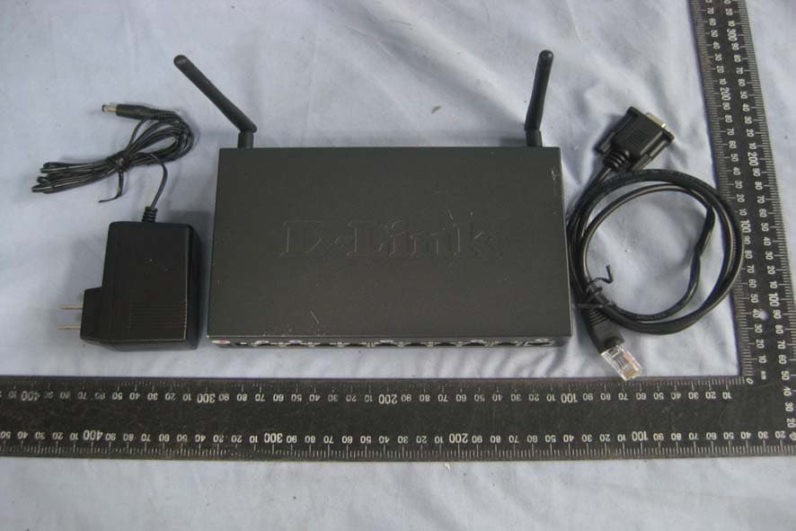
Click to zoom
Application Details
- Equipment Class
- DTS - Digital Transmission System
- Date of Grant
- Jun 25, 2011
- Application Purpose
- Original Equipment
- Date of Application
- Jun 25, 2011
- Equipment Note
- Wireless N Service Router
- Frequency Range
- 2422.00000000 - 2452.00000000
- Company
- D-Link Corporation
- Country
- United States
Documents & Files
Document Text
Text extracted from the exhibit documents filed with the FCC. Open a document above to read the original.
Users Manual
À≤∑∫∑ªº ժƙ∑Ωª≠ Œ± ́ ̈ªÆ À≠ªÆ ”ø≤ ́ø¥ ‹ÕŒÛÓΓ Ò Î Ò Î“ Ò Ô Ò Ô“ ªÆÚ ÔÚÌ ∏ ̈ ̈∞ÊÒÒ≠ªΩ ́Æ∑ ̈ßÚº¥∑≤μÚΩ±≥ fi ́∑¥º∑≤𠓪 ̈©±Æμ≠ ∫±Æ –ª±∞¥ª Õ≥ø¥¥ fi ́≠∑≤ª≠≠ Ÿø ̈ª©øß Õ±¥ ́ ̈∑±≤ User Manual Unified Services Router D-Link Corporation Copyright © 2011. http://www.dlink.com Unified Services Router User Manual 1 User Manual DSR-250N / DSR-500 / 500N / 1000 / 1000N Unified Services Router Version 1.03 Copyright © 2011 Copyright Notice This publication, including all photographs, illustrations and software, is protected under international copyright laws, with all rights reserved. Neither this manual, nor any of the material contained herein, may be reproduced without written consent of the author. Disclaimer The information in this document is subject to change without notice. The manufacturer makes no representations or warranties with respect to the contents hereof and specifically disclaim any implied warranties of merchantability or fitness for any particular purpose. The manufacturer reserves the right to revise this publication and to make changes from time to time in the content hereof without obligation of the manufacturer to notify any person of such revision or changes. Limitations of Liability UNDER NO CIRCUMSTANCES SHALL D-LINK OR ITS SUPPLIERS BE LIABLE FOR DAMAGES OF ANY CHARACTER (E.G. DAMAGES FOR LOSS OF PROFIT, SOFTWARE RESTORATION, WORK STOPPAGE, LOSS OF SAVED DATA OR ANY OTHER COMMERCIAL DAMAGES OR LOSSES) RESULTING FROM THE APPLICATION OR IMPROPER USE OF THE D-LINK PRODUCT OR FAILURE OF THE PRODUCT, EVEN IF D-LINK IS INFORMED OF THE POSSIBILITY OF SUCH DAMAGES. FURTHERMORE, D- LINK WILL NOT BE LIABLE FOR THIRD-PARTY CLAIMS AGAINST CUSTOMER FOR LOSSES OR DAMAGES. D-LINK WILL IN NO EVENT BE LIABLE FOR ANY DAMAGES IN EXCESS OF THE AMOUNT D-LINK RECEIVED FROM THE END-USER FOR THE PRODUCT. Unified Services Router User Manual 2 Table of Contents Chapter 1. Introduction ..................................................................................................................... 10 1.1 About this User Manual ..................................................................................... 11 1.2 Typographical Conventions ............................................................................... 11 Chapter 2. Configuring Your Network: LAN Setup ......................................................................... 13 2.1 LAN Configuration .............................................................................................. 13 2.1.1 LAN Configuration in an IPv6 Network ............................................................. 16 2.1.2 Configuring IPv6 Router Advertisements ......................................................... 18 2.2 VLAN Configuration ........................................................................................... 21 2.2.1 Associating VLANs to ports ............................................................................... 22 2.3 Configurable Port: DMZ Setup .......................................................................... 24 2.4 Universal Plug and Play (UPnP) ....................................................................... 25 2.5 Captive Portal ..................................................................................................... 27 Chapter 3. Connecting to the Internet: WAN Setup ....................................................................... 28 3.1 Internet Setup Wizard ........................................................................................ 28 3.2 WAN Configuration ............................................................................................ 29 3.2.1 WAN Port IP address......................................................................................... 30 3.2.2 WAN DNS Servers............................................................................................. 30 3.2.3 DHCP WAN ........................................................................................................ 30 3.2.4 PPPoE ................................................................................................................ 31 3.2.5 Russia L2TP and PPTP WAN ........................................................................... 34 3.2.6 WAN Configuration in an IPv6 Network ........................................................... 35 3.2.7 Checking WAN Status ....................................................................................... 37 3.3 Bandwidth Controls ............................................................................................ 39 3.4 Features with Multiple WAN Links .................................................................... 41 3.4.1 Auto Failover ...................................................................................................... 41 3.4.2 Load Balancing .................................................................................................. 42 3.4.3 Protocol Bindings ............................................................................................... 43 3.5 Routing Configuration ........................................................................................ 44 3.5.1 Routing Mode ..................................................................................................... 44 3.5.2 Dynamic Routing (RIP) ...................................................................................... 46 3.5.3 Static Routing ..................................................................................................... 47 3.6 Configurable Port - WAN Option ....................................................................... 49 3.7 WAN Port Settings ............................................................................................. 51 Chapter 4. Wireless Access Point Setup ........................................................................................ 53 4.1 Wireless Settings Wizard .........................................…
Text truncated - open the document above for the full version.
Users Manual
Unified Services Router User Manual 149 Symptom: Router can obtain an IP address, but PC is unable to load Internet pages. Recommended action: 1. Ask your ISP for the addresses of its designated Domain Name System (DNS) servers. Configure your PC to recognize those addresses. For details, see your operating system documentation. 2. On your PC, configure the router to be its TCP/IP gateway. 11.2 Date and time Symptom: Date shown is January 1, 1970. Possible cause: The router has not yet successfull y reached a network time server (NTS). Recommended action: 1. If you have just configured the router, wait at least 5 minutes, select Administration > Time Zone, and recheck the date and time. 2. Verify your Internet access settings. Symptom: Time is off by one hour. Possible cause: The router does not automatically adjust for Daylight Savings Time. Recommended action: 1. Select Administration > Time Zone and view the current date and time settings. 2. Click to check or uncheck ―Automatically adjust for Daylight Savings Time‖, then click Apply. 11.3 Pinging to Test LAN Connectivity Most TCP/IP terminal devices and firewalls contain a ping utility that sends an ICMP echo-request packet to the designated device. The DSR responds with an echo reply. Troubleshooting a TCP/IP network is made ver y easy by using the ping utility in your PC or workstation. 11.3.1 Testing the LAN path from your PC to your router 1. From the PC‘s Windows toolbar, select Start > Run. 2. Type ping <IP_address> where <IP_address> is the router‘s IP address. Example: ping 192.168.10.1. 3. Click OK. Unified Services Router User Manual 150 4. Observe the display: If the path is working, you see this message sequence: Pinging <IP address> with 32 bytes of data Repl y from <IP address>: bytes=32 time=NN ms TTL=xxx If the path is not working, you see this message sequence: Pinging <IP address> with 32 bytes of data Request timed out 5. If the path is not working, Test the physical connections between PC and router If the LAN port LED is off, go to the ―LED displays‖ section on page B- 1 and follow instructions for ―LAN or Internet port LEDs are not lit.‖ Verify that the corresponding link LEDs are lit for your network interface card and for any hub ports that are connected to your workstation and firewall. 6. If the path is still not up, test the network configuration: Verify that the Ethernet card driver soft ware and TCP/IP software are installed and configured on the PC. Verify that the IP address for the router and PC are correct and on the same subnet. 11.3.2 Testing the LAN path from your PC to a remote device 1. From the PC‘s Windows toolbar, select Start > Run. 2. Type ping -n 10 <IP_address> where -n 10 specifies a maximum of 10 tries and <IP address> is the IP address of a remote device such as your ISP‘s DNS server. Example: ping -n 10 10.1.1.1. 3. Click OK and then observe the display (see the previous procedure). 4. If the path is not working, do the following: Check that the PC has the IP address of your firewall listed as the default gatewa y. (If the IP configuration of your PC is assigned by DHCP, this information is not visible in your PC‘s Network Control Panel.) Unified Services Router User Manual 151 Verify that the network (subnet) address of your PC is different from the network address of the remote device. Verify that the cable or DSL modem is connected and functioning. Ask your ISP if it assigned a hostname to your PC. If yes, select Network Configuration > WAN Settings > Ethernet ISP Settings and enter that hostname as the ISP account name. Ask your ISP i f it rejects the Ethernet MAC addresses of all but one of your PCs. Many broadband ISPs restrict access by allowing traffic from the MAC address of only your broadband modem; but some ISPs additionally restrict access to the MAC address of just a single PC connected to that modem. If this is the case, configure your firewall to clone or spoof the MAC address from the authorized PC. 11.4 Restoring factory-default configuration settings To restore factor y-default configuration settings, do either of the following: 1. Do you know the account password and IP address? If yes, select Administration > Settings Backup & Upgrade and click default. If no, do the following: On the rear panel of the router, press and hold the Reset button about 10 seconds, until the test LED lights and then blinks. Rel ease the button and wait for the router to reboot. 2. If the router does not restart automatically; manually restart it to make the default settings effective. 3. After a restore to factory defaults —whether initiated from the configuration interface or the Reset button — the following settings apply: LAN IP address: 192.168.10.1 Username: admin Password: password DHCP server on LAN: enabled WAN port configuration: Get configuration via DHCP Chapter 12. Credits Microsoft, Windows are registered trademarks of Microsoft Corp. Linux is a registered trademark of Linus Torvalds. UNIX is a registered trademark of The Open Group. Unified Services Router User Manual 154 Appendix A. Glossary ARP Address Resolution Protocol. Broadcast protocol for mapping IP addresses to MAC addresses. CHAP Challenge-Handshake Authentication Protocol. Protocol for authenticating users to an ISP. DDNS Dynamic DNS. System for updating domain names in real time. Allows a domain name to be assigned to a device with a dynamic IP address. DHCP Dynamic Host Configuration Protocol. Protocol for allocating IP addresses dynamically so that addresses can be reused when hosts no longer need them. DNS Domain Name System. Mechanism for translating H.323 IDs, URLs, or e-mail IDs into IP addresses. Also used to assist in locating remote gatekeepers and to map IP addresses to hostnames of administrative domains. FQDN Fully qualified domain name. Complete domain name, including the host portion. Example: serverA.companyA.com. FTP File Transfer Protocol. Protocol for transf…
Text truncated - open the document above for the full version.
Cover Letter(s)
1 Lucy Tsai From:[email protected] Sent: 2011年6月24日星期五 下午 7:42 To: Lucy Tsai Cc: Lucy Tsai Subject: 回信: D Link Corporation, //KA2SR250NA1 //AN11T0374 Dear Lucy Please see my reply, Best regards, 蕭若茵 / Jill Shiau 程智科技股份有限公司 Compliance Certification Services Inc. Tel: 886-3-324-0332#27 Fax: 886-3-324-7460 E-Mail: [email protected] 寄件人: <[email protected]> 收件人: <[email protected]> 副本抄送: <[email protected]> 日期: 2011/06/01 下午 03:46 主旨: D Link Corporation, //KA2SR250NA1 //AN11T0374 Hi, Jill, Please address following issues. Q#1: According to page 13(Part 1) of user manual, only DSR-1000 and DSR-1000N support for the 3G wireless WAN USB dongle. Please explain the function of USB port designed for DSR-250N. 6/20 Jill The USB Port of DSR-250N is only using for USB External HDD or USB external disk. This EUT don't support the 3.5G Function. Q#2: Page 64 (Part 1) of user manual mentioned that channel is selectable which is not acceptable. Please provide an attestation letter to state that only 1-11 channels are available in USA, other channels will be disabled by software. 6/20 Jill Here is channels selection Letter. 2 Q#3: User manual does not include RF exposure statements for model DSR-250N. Please check and update. FYI: As for IC filing, the RSS-GEN rule section quoted in page 114 of user manual (Part 2) are incorrect Please check and update. And, per RSS-GEN Section 5.3 , the related statements or information to user shall be in both English and French. Therefore, the statements in current user manual are not enough to address IC filing. Also, be noted that RF ex posure statements are missing and the antenna gain indicated does not agree with antenna specification. /20 Jill Revised the RF exposure statement in Page 222 of User Manaul. Q#4: Regarding PPSD and conducted s purious emission tests, please take a look to KDB 662911 D01 Multiple Transmitter Output v01 firstly. According to it, test with combiner is no longer acceptable. Instead, it needs to be measured with each individual and sum. Two methods are provided inside the KDB. Looking to the test report, PPSD test has included the combiner mode. Please remove the combiner mode from PPSD test result and sum the total PPSD from each individual chain. As for RF conducted spurious emission test for MIMO mode, it looks like test was done with combiner. Please re-do the test with each individual chain. 6/20 Jill According the KDB, revised PPSD in page 37 ~ 46 of test report.. Q#5: Please provide radiated band edge test data. 6/20 Jill Radiated Band edge test data, please see in page 29 ~ 36 of test report Best Regards, Lucy Tsai/UL CCS The items indicated above must be submitted before processing can continue on the above referenced application. Failure to provide the requested information within 30 days of the original e- mail date may result in application dismissal and forfeiture of the filing fee. Also, please note that partial responses increase processing time and should not be submitted. Any questions about the content of this correspondence should be directed to the e-mail address listed below the name of the sender. Revised documentation should not be emailed , but instead should be submitted through "Add Attachment?function at the UL-CCS website. Please have your Assessment Number and FCC ID/IC Certification number hand y. You may use the following link: https://cert.ccsemc.com/filing/ ______________________________________________________________ This e-mail transmission is confidential and intended solely for being reviewed by the recipient(s) identified above. If you are not an identified recipient, please ensure that this communication remains confidential and promptly return it to the sender. Please contact immediately by phone (Tel: 886-2-2299-9720) for any problem with this transmission. Thank you for your attention.
External Photos
Report No: T110406202 Page 1 / 8 Rev.00 EXTERNAL PHOTOGRAPHS OF EUT Report No: T110406202 Page 2 Rev.00 Report No: T110406202 Page 3 Rev.00
ID Label/Location Info
80.00 mm 3 5 . 0 m m S/N: Model No.: DSR-250N H/W Ver.:A1 F/W Ver.:XXXX MADE IN CHINA QBDM1ym000001 P/N:ISR250NLNA...A1E MAC ID:XXXXXXXXXXXX (C) FCC ID:KA2SR250NA1 IC:4216A-SR250NA1 0984 ACN 052 202 838 Z576 This device complies with part 15 of the FCC Rules. Operation is subject to the following conditions: (1)this device may not cause harmful interference and (2)this device must accept any interference received, including interference that may cause undesired operation.
Internal Photos
Report No: T110406202 Page 4 Rev.00 INTERNAL PHOTOGRAPHS OF EUT Report No: T110406202 Page 5 Rev.00 RF Module Report No: T110406202 Page 6 Rev.00 Report No: T110406202 Page 7 Rev.00 Report No: T110406202 Page 8 Rev.00
Test Report
Compliance Certification Services Inc. Report No.: T110406202-RP1 FCC ID: KA2SR250NA1 Date of Issue: June 24, 2011 Page 1 / 88 Rev.00 SFCC 47 CFR PART 15 SUBPART C TEST REPORT For Wireless N Service Router Model: DSR-250N Trade Name: D-Link Issued to D Link Corporation 17595 Mt. Herrmann , Fountain Valley, California 92708, United States Issued by Compliance Certification Services Inc. No.81-1, Lane 210, Bade 2nd Rd., Lujhu Township, Taoyuan County 33841,Taiwan, R.O.C. TEL: 886-3-324-0332 FAX: 886-3-324-5235 http://www.ccsrf.com [email protected] Note: This report shall not be reproduced except in full, without the written approval of Compliance Certification Services Inc. This document may be altered or revised by Compliance Certification Services Inc. personnel only, and shall be noted in the revision section of the document. The client should not use it to claim product endorsement by TAF, A2LA, NIST or any government agencies. The test results in the report only apply to the tested sample. Compliance Certification Services Inc. Report No.: T110406202-RP1 FCC ID: KA2SR250NA1 Date of Issue: June 22, 2011 Page 2 Rev.00 This report shall not be reproduced except in full, without the written approval of Compliance Certification Services. Revision History Rev. Issue Date Revisions Effect Page Revised By 00 June 22, 2011 Initial Issue ALL Jill Shiau Compliance Certification Services Inc. Report No.: T110406202-RP1 FCC ID: KA2SR250NA1 Date of Issue: June 22, 2011 Page 3 Rev.00 This report shall not be reproduced except in full, without the written approval of Compliance Certification Services. TABLE OF CONTENTS 1. TEST RESULT CERTIFICATION ...........................................................................................4 2. EUT DESCRIPTION................................................................................................................5 3. TEST METHODOLOGY..........................................................................................................6 3.1 EUT CONFIGURATION.....................................................................................................6 3.2 EUT EXERCISE.................................................................................................................6 3.3 GENERAL TEST PROCEDURES .....................................................................................6 3.4 FCC PART 15.205 RESTRICTED BANDS OF OPERATIONS .........................................7 3.5 DESCRIPTION OF TEST MODES ....................................................................................8 4. INSTRUMENT CALIBRATION ...............................................................................................9 4.1 MEASURING INSTRUMENT CALIBRATION ....................................................................9 4.2 MEASUREMENT EQUIPMENT USED ..............................................................................9 4.3 MEASUREMENT UNCERTAINTY...................................................................................10 5. FACILITIES AND ACCREDITATIONS .................................................................................11 5.1 FACILTIES .......................................................................................................................11 5.2 EQUIPMENT....................................................................................................................11 5.3 TABLE OF ACCREDITATIONS AND LISTINGS .............................................................12 6. SETUP OF EQUIPMENT UNDER TEST ..............................................................................13 6.1 SETUP CONFIGURATION OF EUT ................................................................................13 6.2 SUPPORT EQUIPMENT .................................................................................................13 7. FCC PART 15.247 REQUIREMENTS ..................................................................................14 7.1 6 DB BANDWIDTH ............................................................................................................14 7.2 PEAK POWER .................................................................................................................25 7.3 AVERAGE POWER .........................................................................................................27 7.4 BAND EDGES MEASUREMENT.....................................................................................29 7.5 PEAK POWER SPECTRAL DENSITY ............................................................................46 7.6 SPURIOUS EMISSIONS .................................................................................................57 7.7 POWERLINE CONDUCTED EMISSIONS.......................................................................80 8. APPENDIX I RADIO FREQUENCY EXPOSURE .................................................................83 9. APPENDIX II PHOTOGRAPHS OF TEST SETUP...............................................................85 Compliance Certification Services Inc. Report No.: T110406202-RP1 FCC ID: KA2SR250NA1 Date of Issue: June 22, 2011 Page 4 Rev.00 This report shall not be reproduced except in full, without the written approval of Compliance Certification Services. 1. TEST RESULT CERTIFICATION Applicant: D Link Corporation 17595 Mt. Herrmann , Fountain Valley, California 92708, United States Manufacturer: CAMEO Communications, Inc. No. 276, Sinhu 1st Rd., Neihu District, Taipei City 114 Taiwan, R.O.C. Equipment Under Test: Wireless N Service Router Trade Name: D-Link Model: DSR-250N Date of Test: March 23 ~ June 22, 2011 APPLICABLE STANDARDS STANDARD TEST RESULT FCC 47 CFR Part 15 Subpart C No non-compliance noted We hereby certify that: The above equipment was tested by Compliance Certification Services Inc. The test data, data evaluation, test procedures, and equipment configurations shown in this report were made in accordance with the pro…
Text truncated - open the document above for the full version.
Test Setup Photos
Compliance Certification Services Inc. Report No.: T110406202-RP1 FCC ID: KA2SR250NA1 Date of Issue: April 22, 2011 Page 76 Rev.00 This report shall not be reproduced except in full, without the written approval of Compliance Certification Services. 9. APPENDIX II PHOTOGRAPHS OF TEST SETUP Radiated Emission Set up Photos Below 1GHz Compliance Certification Services Inc. Report No.: T110406202-RP1 FCC ID: KA2SR250NA1 Date of Issue: April 22, 2011 Page 77 Rev.00 This report shall not be reproduced except in full, without the written approval of Compliance Certification Services. Above 1GHz Compliance Certification Services Inc. Report No.: T110406202-RP1 FCC ID: KA2SR250NA1 Date of Issue: April 22, 2011 Page 78 Rev.00 This report shall not be reproduced except in full, without the written approval of Compliance Certification Services. Conducted Emission Setup Photos Compliance Certification Services Inc. Report No.: T110406202-RP1 FCC ID: KA2SR250NA1 Date of Issue: April 22, 2011 Page 79 Rev.00 This report shall not be reproduced except in full, without the written approval of Compliance Certification Services. Powerline Conducted Emissions Setup Photos
Contact Information
Applicant
Brett Adair(General Counsel)
Test Firm
Compliance Certification Services Inc.Kurt Chen
Technical Specifications
| # | Rule Parts | Frequency Range | Power Output |
|---|---|---|---|
| 3 | 15C | 2.42 GHz - 2.45 GHz | 354.00 mW |
Other Applications from D-Link Corporation

KA2CS6012A1
Jul 07, 20262K Fixed Indoor Cloud Camera, 2K Fixed Indoor Wi-Fi Camera
Equipment Class
DTS - Digital Transmission SystemKA2AE65UA1
Mar 02, 2026Wi-Fi 7 BE6500 USB 3.0 Dongle
Equipment Class
NII - Unlicensed National Information Infrastructure TXKA2APE9560A1
Nov 17, 2025BE9500 Celling mount Access Point
Equipment Class
6ID - 15E 6 GHz Low Power Indoor Access PointKA2AX9UA1
Dec 04, 2024AX900 Wi-Fi 6 USB Adapter, Wi-Fi 6 AX900 USB 2.0 Dongle
Equipment Class
DSS - Part 15 Spread Spectrum TransmitterKA2AC13UA1
Dec 04, 2024AC1300 Wi-Fi 5 USB Adapter, Wi-Fi 5 AC1300 USB 2.0 Dongle
Equipment Class
DTS - Digital Transmission System