KA2TW1130Wireless VPN Router
D-Link Corporation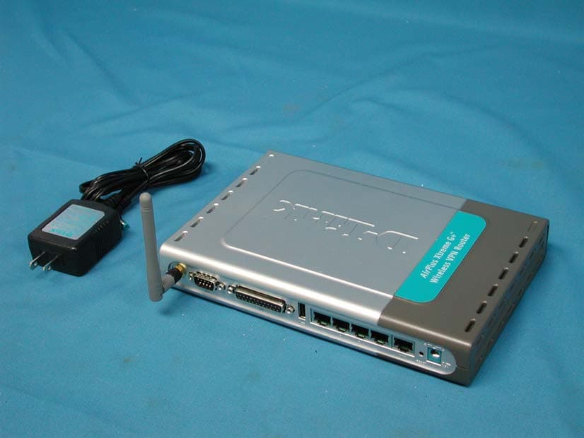
Click to zoom
Application Details
- Equipment Class
- DTS - Digital Transmission System
- Date of Grant
- Feb 23, 2004
- Application Purpose
- Original Equipment
- Date of Application
- Feb 23, 2004
- Equipment Note
- Wireless VPN Router
- Frequency Range
- 2412.00000000 - 2462.00000000
- Company
- D-Link Corporation
- Country
- United States
Documents & Files
Document Text
Text extracted from the exhibit documents filed with the FCC. Open a document above to read the original.
Users Manual
High-Speed Enhanced 2.4 GHz Manual Wireless VPN Router Building Networks for People 10/01/2003 DI-824VUP AirPlus Xtreme G D-Link 2 Contents Package Contents................................................................................ 3 Introduction............................................................................................ 4 Wireless Basics .................................................................................... 6 Getting Started...................................................................................... 9 Using the Configuration Menu.............................................................. 11 Networking Basics.............................................................................. 69 Reset to Factory Default Settings........................................................ 98 Technical Specifications...................................................................... 99 Frequently Asked Questions.............................................................. 100 Contacting Technical Support............................................................ 149 Warranty and Registration.................................................................150 Installing the Print Server Software...................................................... 65 Configuring on Windows 98se/Me Platforms....................................... 67 3 Contents of Package: D-Link AirPlus Xtreme G DI-824VUP High-Speed Enhanced 2.4GHz Wireless VPN Router Power Adapter – 5V DC / 2.5A Manual on CD Quick Installation Guide Package Contents Note: Using a power supply with a different voltage rating than the one included with the DI-824VUP will cause damage and void the warranty for this product. If any of the above items are missing, please contact your reseller. System Requirements For Configuration: Computer with Windows, Macintosh, or Linux-based operating system with an installed Ethernet adapter Internet Explorer version 6.0 or Netscape Navigator version 6.0 and above, with JavaScript enabled Ethernet-Based Cable or DSL Modem 4 Introduction The D-Link AirPlus Xtreme G DI-824VUP Wireless Broadband Router is an enhanced 802.11b high-performance, wireless router with a printer port. It is an ideal way to extend the reach and number of computers connected to your wireless network. Unlike most 802.11g routers, the DI-824VUP is capable of data transfer speeds up to 54 Mbps (compared to the standard 11 Mbps) when used with other D- Link AirPlus Xtreme G products such as the DWL-G650 and DWL-G520 Wireless Adapters. After completing the steps outlined in the Quick Installation Guide (included in your package) you will have the ability to share information and resources, as well as share a printer wirelessly on your network. The DI-824VUP is compatible with most popular operating systems, including Macintosh, Linux and Windows, and can be integrated into a large network. This Manual is designed to help you connect the Router and D-Link AirPlus 2.4GHz Wireless Adapters into a network in Infrastructure mode. Please take a look at the Getting Started section in this manual to see an example of an Infrastructure network using the DI-824VUP. 5 Connections DHCP server support enables all networked computers to automatically receive IP addresses Wireless connection of up to 54Mbps Web-based interface for Management Access Control to manage users on the network Maximum reliability, throughput and connectivity with automatic data rate switching Stronger network security with 256-bit encryption Printer port enables connection to a network printer Connects multiple computers to an Ethernet Broadband (Cable or DSL) modem to share the Internet connection Supports VPN pass-through, providing added security Advanced Firewall features for added network security Features & Benefits Note: Please refer to the Resetting the DI-824VUP to the Factory Defualt Settings section in this manual for instructions on how to use the Reset button. WAN and LAN ports auto detect cable types (straight-through or cross-over) UPnP supported LAN ports provide connections to Ethernet- enabled devices. Pressing the Reset Button restores the router to its original factory default settings. All ports (both LAN and WAN) auto-sense cable types to accomodate straight-through or cross-over cable. Receptor for the Power Adapter. WAN port is the connection for the Ethernet cable to the Cable or DSL modem. COM port is the connection to another COM port or back- up dial-up modem. The LPT port or USB port is used to connect to your local printer. 6 LEDS LED stands for Light-Emitting Diode. The DI-824VUP has the following LEDs as described below: LED LED Activity Power A steady light indicates a connection to a power source WAN A solid light indicates connection on the WAN port. This LED blinks during data transmission WLAN A blinking light indicates that the wireless segment is ready. This LED blinks during wireless data transmission. D-Link AirPlus wireless products are based on industry standards to provide easy-to- use and compatible high-speed wireless connectivity within your home, business, or public access wireless networks. Strictly adhering to the IEEE standard, the D-Link AirPlus wireless family of products will allow you to securely access the data you want, when and where you want it. You will be able to enjoy the freedom that wireless networking delivers. A wireless local area network (WLAN) is a cellular computer network that transmits and receives data with radio signals instead of wires. Wireless LANs are used increasingly in both home and office environments, and public areas such as airports, coffee shops, and universities. Innovative ways to utilize WLAN technology are helping people to work and communicate more efficiently. Increased mobility and the absence of cabling and other fixed infrastructure have proven to be beneficial for many users. Wireless Basics Flashes onc…
Text truncated - open the document above for the full version.
Users Manual
29 Using the Configuration Menu Home > VPN Settings > Tunnel > Manual Remote Subnet The subnet of the remote VPN gateway’s local network. It can be a host, a partial subnet, or a whole subnet. Remote Netmask The subnet of the remote VPN gateway’s local network. It can be a host, a partial subnet, or a whole subnet. Remote Gateway The WAN IP address of remote VPN gateway. Local Subnet The subnet of the VPN gateway’s local network. It can be a host, a partial subnet, or a whole subnet. Local Netmask Local netmask combined with local subnet to form a subnet domain. Aggressive Mode Enabling this mode will accelerate establishing tunnel, but the device will have less security. Tunnel Name Current tunnel name. Remote SPI The value of the remote SPI should be set in hex format. Local SPI The value of the local SPI should be set in hex format. Method The set of rules applied when connecting to the VPN gateway. 30 Using the Configuration Menu Home > VPN Settings > Tunnel > Manual Continued... Encapsulation Protocol There are two protocols that can be selected: ESP and AH. Encryption Algorithm There are two algorithms that can be selected: 3DES and DES. Authentication Algorithm There are two algorithms that can be selected: SHA1 and MD5. Encryption Key For DES, the encryption key is 8 bytes (16 Char.). For 3DES, the encryption key is 24 bytes (48 Char.). Authentication Key For MD5, the authentication algorithm is16 bytes (32 Char.). For SHA1, the authentication algorithm is 20 bytes.(40 Char.). Life Time Enter in the life time value. Life Time Unit There are two units that can be selected: Second and KB. 31 Home > VPN Settings > Dynamic VPN Tunnel Using the Configuration Menu Local Subnet The subnet of the VPN gateway’s local network. It can be a host, a partial subnet, or a whole subnet. Local Netmask The netmask of the VPN gateway’s local network. Aggressive Mode Enabling this mode will accelerate establishing the tunnel, but the device will have less security. Tunnel Name Current tunnel name. This feature works with a VPN software client so the DI- 824VUP does not need to know the IP address of the remote clients. Dynamic VPN There are three parts that are necessary to setup the configuration of IKE for the dedicated tunnel: basic setup, IKE proposal setup, and IPSec proposal setup. Basic setup includes the setting of following items: local subnet, local netmask, remote subnet, remote netmask, remote gateway, and pre-shared key. The tunnel name is derived from the previous page of VPN setting. IKE proposal setup includes the setting of a set of frequent-used IKE proposals and selecting from the set of IKE proposals. VPN Settings - IKE 32 Using the Configuration Menu Home > VPN Settings > Dynamic VPN Tunnel Continued... Preshared Key The first key that supports IKE mechanism of both VPN gateways for negotiating further security keys. The pre- shared key must be the same for both endpoint gateways. IKE Proposal index Click the button to setup a set of frequent-used IKE proposals and select from the set of IKE proposals for the dedicated tunnel. IPSec Proposal index Click the button to setup a set of frequent-used IPSec proposals and select from the set of IKE proposals for the dedicated tunnel. 33 Using the Configuration Menu Home > VPN Settings > Dynamic VPN Tunnel > Set IKE Proposal IKE Proposal index Proposal Name DH Group Encrypt algorithm Auth algorithm A list of selected proposal indexes from the IKE proposal pool listed below. There are three groups that can be selected: group 1 (MODP768), group 2 (MODP1024), and group 5 (MODP1536). There are two algorithms that can be selected: 3DES and DES. It indicates which IKE proposal to be focused. There are two algorithms that can be selected: SHA1 and MD5. 34 Life Time Enter in the life time value. Life Time Unit There are two units that can be selected: second and KB. Proposal ID The identifier of IKE proposal can be chosen for adding the corresponding proposal to the dedicated tunnel. Add to Click it to add the chosen proposal indicated by proposal ID to IKE Proposal index list. Using the Configuration Menu Home > VPN Settings > Dynamic VPN Tunnel > Set IKE Proposal Continued... 35 Using the Configuration Menu Home > VPN Settings > Dynamic VPN Tunnel > Set IPSEC Proposal IPSec Proposal index A list of selected proposal indexes from the IPSec proposal pool listed below. Proposal Name DH Group There are three groups that can be selected: group 1 (MODP768), group 2 (MODP1024), and group 5 (MODP1536). Encap protocol There are two protocols that can be selected: ESP and AH. Encrypt algorithm There are two algorithms that can be selected: 3DES and DES. This is the name used to classify the IPSec proposal. Auth algorithm There are two algorithms that can be selected: SHA1 and MD5. 36 Using the Configuration Menu Home > VPN Settings > Dynamic VPN Tunnel > Set IPSEC Proposal Continued... Life Time Enter in a life time value. Life Time Unit There are two units that can be selected: second and KB. Proposal ID The identifier of IPSec proposal can be chosen for adding the corresponding proposal to the dedicated tunnel. Add to Click it to add the chosen proposal indicated by proposal ID to IPSec Proposal index list. 37 Home > VPN Settings > L2TP Server Setting Using the Configuration Menu Enable L2TP Server Click to enable the L2TP Server function. Virtual IP of L2TP Server Enter your Virtual IP address to access the L2PT server. Authentication Protocol Select one of the following authentication protocols: PAP, CHAP, or MSCHAP. Tunnel Name Current tunnel name. User Name Password Enter in the password for the L2TP account. Enter in the username for the L2TP account. 38 Home > VPN Settings > PPTP Server Setting Using the Configuration Menu Enable PPTP Server Click to enable the PPTP Server function. Virtual IP of PPTP Server Enter your Virtual IP address to access thePPPT server. Authentication Protocol Select one of the following authentication protocols: PAP,…
Text truncated - open the document above for the full version.
Users Manual
53 Using the Configuration Menu Tools > Admin Password Remote Management To change the administrator or user password, enter in the old pass- word and enter the new password twice to confirm. You can change the administrator and user passwords here. It is recommended that you change the administrator password from the default setting.The default password is blank (nothing). Remote Management allows the device to be configured through the WAN (Wide Area Network) port from the Internet using a web browser. A username and password is still required to access the browser-based management interface. IP Address Internet IP Address of the computer that has access to the DI-824VUP. If the IP Address is set to 0.0.0.0, this allows all Internet IP ad- dresses to access the DI-824VUP. Port The port number used to access the DI-824VUP. Example:http:// x.x.x.x:8080, where x.x.x.x. is the WAN IP address of the DI-824VUP+ and 8080 is the port used for the Web Manage- ment interface. 54 Using the Configuration Menu Tools > Time Enable NTP (Network Time Protocol). Select to synchronize the time on the DI-824VUP to an NTP server. Set Device Date and Time You can manually set the time on your network here. You will need to set the time zone corresponding to your location. The time can be set manually or the device can connect to a NTP (Network Time Protocol) server to retrieve the time. NTP is short for Network Time Protocol, an Internet standard protocol that assures accurate synchronization to the millisecond of computer clock times in a network of computers. 55 Using the Configuration Menu Tools > System Click Save to save the current settings to the local Hard Drive. Click Browse to find the settings file, then click Load. Save Settings to Local Hard Drive Load Settings from Local Hard Drive Restore to Factory Default Settings Click Restore to restore the factory default settings. The current system settings can be saved as a file onto the local hard drive. The saved file or any other saved setting file created by the DI-824VUP can be uploaded into the unit. To reload a system settings file, click on “Browse” to search the local hard drive for the file to be used. The device can also be reset back to factory default settings by clicking on “Reset to Default” button. Use the restore feature only if necessary. This will erase previously saved settings for the unit. Make sure to save your system settings before doing a factory restore. 56 Using the Configuration Menu Tools > Firmware Browse After you have downloaded the new firmware, click Browse in this window to locate the firmware update on your hard drive. Click Apply to complete the firmware upgrade. Note! Do not power off the unit when it is being upgraded. When the upgrade is complete, the unit will be restarted automatically. You can upgrade the firmware of the device using this tool. Make sure that the firmware you want to use is saved on the local hard drive of the computer. Click on “Browse” to search the local hard drive for the firmware to be used for the update. Upgrading the firmware will not change any of your system settings but it is recommended that you save your system settings before doing a firmware upgrade. Please check the D-Link support site for firmware updates at http://support.dlink.com. 57 Using the Configuration Menu Tools > Misc Block WAN Ping Click Enable to block the WAN ping. Computers on the Internet will not get a reply back from the DI-824VUP when it is being “ping”ed. This may help to increase security. Restart Device Click Reboot to restart the unit. Ping Test In the open box, enter in a URL (i.e., www.dlink.com) or an IP address and click on Ping to test your internet connection. SPI Mode When this feature is enabled, the router will record the packet information passed through the router such as IP address, port address, ACK, SEQ number, and so on. The router will also check every incoming packet to detect if it is valid. DoS When DoS is enabled, the router will prevent Denial of Service attacks on all computers connected to the DI-824VUP. 58 Using the Configuration Menu Tools > Misc (Continued) Non-standard FTP port If an FTP server you want to access is not using the standard port 21, then enter in the port number that the FTP server is using in- stead. UPnP UPnP is short for Universal Plug and Play which is a networking architecture that provides compatibility among networking equip- ment, software, and peripherals. The DI-824VUP is a UPnP enabled router and will only work with other UPnP devices/softwares. If you do not want to use the UPnP Functionality, it can be disabled by selecting “Disabled”. VPN Pass- Through The device supports VPN (Virtual Private Network) pass-through for both PPTP (Point-to-Point Tunneling Protocol) and IPSec (IP Secu- rity). Once VPN pass-through is enabled, there is no need to open up virtual services. Multiple VPN connections can be made through the device. This is useful when you have many VPN clients on the LAN. 59 Using the Configuration Menu Status > Device Info This screen displays information about the DI-824VUP such as WAN, LAN, and Wire- less status. DHCP Renew Use this button to reconnect to your ISP, if your WAN connection is set up for DHCP. DHCP Release Use this button to disconnect from your ISP, if your WAN connection is set up for DHCP. 60 Using the Configuration Menu Status > Log This screen displays activities occurring on the DI-824VUP. Log Settings Click for advanced features (see next page). First Page Click First Page to go to the first page of the log. Last Page Click Last Page to go to the last page of the log. Previous Click Previous to go to the previous page of the log. Next Click Next to go to the next page of the log. Clear Click Clear to clear the current page of the log. 61 Using the Configuration Menu Status > Log > Log Settings Email Address Enter in the email address of the recipient who will receive the email log. Enter in the IP address of a sysl…
Text truncated - open the document above for the full version.
Users Manual
76 Networking Basics Naming your Computer To name your computer, please follow these directions: In Windows XP: Select the Computer Name Tab in the System Properties window. You may enter a Com- puter Description if you wish; this field is optional. To rename the computer and join a domain, Click Change. Click Start (in the lower left corner of the screen). Right-click on My Computer. Select Properties and click. 77 Networking Basics Naming your Computer In this window, enter the Computer name. Select Workgroup and enter the name of the Workgroup. All computers on your network must have the same Workgroup name. Click OK. Checking the IP Address in Windows XP The wireless adapter-equipped computers in your network must be in the same IP Ad- dress range (see Getting Started in this manual for a definition of IP Address Range). To check on the IP Address of the adapter, please do the following: Right-click on the Local Area Connection icon in the task bar. Click on Status. OK 78 Networking Basics Checking the IP Address in Windows XP This window will appear. Click the Support tab. Click Close. Assigning a Static IP Address in Windows XP/2000 Note: Residential Gateways/Broadband Routers will automatically assign IP Ad- dresses to the computers on the network, using DHCP (Dynamic Host Configura- tion Protocol) technology. If you are using a DHCP-capable Gateway/Router you will not need to assign Static IP Addresses. If you are not using a DHCP capable Gateway/Router, or you need to assign a Static IP Address, please follow these instructions: Go to Start. Double-click on Control Panel. 79 Networking Basics Assigning a Static IP Address in Windows XP/2000 Double-click on Network Connections. Single-click on Properties. Right-click on Local Area Connections. 80 Networking Basics Assigning a Static IP Address in Windows XP/2000 Input your IP address and subnet mask. (The IP Addresses on your network must be within the same range. For example, if one computer has an IP Address of 192.168.0.2, the other computers should have IP Addresses that are sequential, like 192.168.0.3 and 192.168.0.4. The subnet mask must be the same for all the computers on the network.) Input your DNS server addresses. (Note: If you are entering a DNS server, you must enter the IP Address of the Default Gateway.) The DNS server information will be supplied by your ISP (Internet Service Provider). Click OK. Click on Internet Protocol (TCP/IP). Click Properties. 81 Networking Basics Assigning a Static IP Address with Macintosh OSX Go to the Apple Menu and se- lect System Preferences. cClick on Network. Select Built-in Ethernet in the Show pull-down menu. Select Manually in the Con- figure pull-down menu. Input the Static IP Address, the Subnet Mask and the Router IP Address in the ap- propriate fields. Click Apply Now. 82 Networking Basics Selecting a Dynamic IP Address with Macintosh OSX Go to the Apple Menu and select System Preferences. Click on Network. Select Built-in Ethernet in the Show pull-down menu. Select Using DHCP in the Configure pull-down menu. Click Apply Now. The IP Address, Subnet mask, and the Router’s IP Address will appear in a few seconds. 83 Networking Basics Checking the Wireless Connection by Pinging in Windows XP and 2000 Checking the Wireless Connection by Pinging in Windows Me and 98 Go to Start > Run > type cmd. A window similar to this one will appear. Type ping xxx.xxx.xxx.xxx, where xxx is the IP Address of the Wireless Router or Access Point. A good wireless connection will show four replies from the Wireless Router or Acess Point, as shown. Go to Start > Run > type command. A window similar to this will appear. Type ping xxx.xxx.xxx.xxx where xxx is the IP Address of the Wireless Router or Access Point. A good wireless connection will show four replies from the wireless router or access point, as shown. 84 Networking Basics Adding and Sharing Printers in Windows XP After you have run the Network Setup Wizard on all the computers in your network (please see the Network Setup Wizard section at the beginning of Networking Basics), you can use the Add Printer Wizard to add or share a printer on your network. Whether you want to add a local printer (a printer connected directly to one computer), share an LPR printer (a printer connected to a print server), or share a network printer (a printer connected to your network through a Gateway/Router), use the Add Printer Wizard. Please follow the directions below: First, make sure that you have run the Network Setup Wizard on all of the computers on your network. On the following pages, we will show you these 3 ways to use the Add Printer Wizard: 1. Adding a local printer 2. Sharing an network printer 3. Sharing an LPR printer For help with other tasks, that we have not covered here, in home or small office net- working, see Using the Shared Documents folder and Sharing files and folders in the Help and Support Center in Microsoft Windows XP. (Other Networking Tasks) 85 Networking Basics Adding a local printer (a printer connected directly to a computer) A printer that is not shared on the network and is connected directly to one computer is called a local printer. If you do not need to share your printer on a network, follow these directions to add the printer to one computer. Go to Start > Printers and Faxes Click on Add a printer. 86 Networking Basics Adding a local printer Click Next. Select Local printer attached to this computer. (Deselect Automati- cally detect and install my Plug and Play printer if it has been selected.) Click Next. Select Use the follow- ing port: From the pull-down menu select the correct port for your printer. (Most computers use the LPT1: port, as shown in the illustration.) Click Next. 87 Networking Basics Adding a local printer Select and highlight the correct driver for your printer. Click Next. (If the correct driver is not d…
Text truncated - open the document above for the full version.
Users Manual
92 Networking Basics Sharing a network printer To check for proper installation: Go to Start > Printers and Faxes. The printer icon will appear at right, indicating proper installation. You have completed adding the printer. To share this printer on your network: Remember the printer name. Run the Add Printer Wizard on all the computers on your network. Make sure you have already run the Network Setup Wizard on all the network computers. After you run the Add Printer Wizard on all the computers in the network, you can share the printer. 93 Networking Basics Sharing an LPR printer To share an LPR printer (using a print server,) you will need a Print Server such as the DP-101P+. Please make sure that you have run the Network Setup Wizard on all the computers on your network. To share an LPR printer, please follow these directions: Go to Start > Printers and Faxes. Click on Add a Printer. The screen to the right will appear. Click Next. Select Local Printer. Click Next. 94 Networking Basics Sharing an LPR printer Select Create a new port. From the pull-down menu, select Standard TCP/IP Port, as shown. Click Next. Please read the instructions on this screen. Click Next. Enter the Printer IP Address and the Port Name, as shown. Click Next. 95 Networking Basics Sharing an LPR printer In this screen, select Custom. Click Settings. Enter the Port Name and the Printer Name or IP Address. Select LPR. Enter a Queue Name (if your Print-Server/ Gateway has more than one port, you will need a Queue name). Click OK. 96 Networking Basics Sharing an LPR printer Click Next. Select Keep existing driver. If the printer driver is already installed, do the following: Click Have Disk. Insert the printer driver disk that came with your printer. Select the printer you are adding from the list of Printers. Click Finish. This screen will show you information about your printer. 97 Networking Basics Sharing an LPR printer Note: You must run the Network Setup Wizard on all the computers on your network before you run the Add Printer Wizard. Please run the Add Printer Wizard on all the computers on your network in order to share the printer. Click Finish to complete the addition of the printer. This screen will display information about your printer. Click Next Select Yes, to print a test page. Click Next Please remember the name of your printer. You will need this information when you use the Add Printer Wizard on the other computers on your network. You can rename your printer if you choose. It is optional. . . 98 After you have tried other methods for troubleshooting your network, you may choose to Reset the DI-824VUP to the factory default settings. To hard-reset the D-Link DI-824VUP to the Factory Default Settings, please do the following: Resetting the DI-824VUP to the Factory Default Settings Use a paper clip to press the Reset button and power on. Locate the Reset button on the back of the DI-824VUP. After you have completed the above steps, the DI- 824VUP will be reset to the factory default settings. Hold for about 5 seconds (do not hold for too long) and then release. (Or, release when the status LEDflashes.) 99 Technical Specifications VPN Pass Through Function PPTP L2TP IPSec Standards IEEE 802.11b IEEE 802.3 LEDs Power WAN LAN WLAN Status COM USB Operating Temperature 32°F to 131°F ( 0°C to 55°C) Humidity 10-90% Power 5V DC / 2.5A IEEE 802.3u 100BASE-TX Fast Ethernet USB 1.1 IEEE 802.11g L = 9.25 inches (233mm) W = 6.5 inches (165mm) H = 1.375 inches (35mm) Dimensions ~2.0oz. (907g) Weight 4 x 10/100 LAN Ports (MDI/MDIX) 1 x 10/100 WAN Port (MDI/MDIX 1 COM Port (Dial-up Modem) 1 Parallel Port (DB25) 1 USB Port Ports LPT 100 Frequently Asked Questions When entering the IP Address of the DI-824VUP (192.168.0.1), you are not connecting to the Internet or have to be connected to the Internet. The device has the utility built-in to a ROM chip in the device itself. Your computer must be on the same IP subnet to connect to the web-based utility. To resolve difficulties accessing a Web utility, please follow the steps below. Step 1 Verify physical connectivity by checking for solid link lights on the device. If you do not get a solid link light, try using a different cable or connect to a different port on the device, if possible. If the computer is turned off, the link light may not be on. The following connections require a Crossover Cable: Computer to Computer Computer to Uplink Port Computer to Access Point Computer to Print Server Computer/XBOX/PS2 to DWL-810 Computer/XBOX/PS2 to DWL-900AP+ Uplink Port to Uplink Port (hub/switch) Normal Port to Normal Port (hub/switch) The following connections require a Straight-through Cable: Computer to Residential Gateway/Router Computer to Normal Port (hub/switch) Access Point to Normal Port (hub/switch) Print Server to Normal Port (hub/switch) Uplink Port to Normal Port (hub/switch) Rule of Thumb: ”If there is a link light, the cable is right.” What type of cable should I be using? Why can ́t I access the Web-based configuration? 101 Frequently Asked Questions (continued) What type of cable should I be using? (continued) What ́s the difference between a crossover cable and a straight-through cable? The wiring in crossover and straight-through cables are different. The two types of cable have different purposes for different LAN configurations. EIA/TIA 568A/568B define the wiring standards and allow for two different wiring color codes as illustrated in the following diagram. *The wires with colored backgrounds may have white stripes and may be denoted that way in diagrams found elsewhere. How to tell straight-through cable from a crossover cable: The main way to tell the difference between the two cable types is to compare the wiring order on the ends of the cable. If the wiring is the same on both sides, it is straight-through cable…
Text truncated - open the document above for the full version.
Contact Information
Applicant
Brett Adair(General Counsel)
Test Firm
DEKRA Testing and Certification Co., Ltd.Sky Hsu
Technical Specifications
| # | Rule Parts | Frequency Range | Power Output |
|---|---|---|---|
| 1 | 15C | 2.41 GHz - 2.46 GHz | 123.00 mW |
Other Applications from D-Link Corporation

KA2CS6012A1
Jul 07, 20262K Fixed Indoor Cloud Camera, 2K Fixed Indoor Wi-Fi Camera
Equipment Class
DTS - Digital Transmission SystemKA2AE65UA1
Mar 02, 2026Wi-Fi 7 BE6500 USB 3.0 Dongle
Equipment Class
NII - Unlicensed National Information Infrastructure TXKA2APE9560A1
Nov 17, 2025BE9500 Celling mount Access Point
Equipment Class
6ID - 15E 6 GHz Low Power Indoor Access PointKA2AX9UA1
Dec 04, 2024AX900 Wi-Fi 6 USB Adapter, Wi-Fi 6 AX900 USB 2.0 Dongle
Equipment Class
DSS - Part 15 Spread Spectrum TransmitterKA2AC13UA1
Dec 04, 2024AC1300 Wi-Fi 5 USB Adapter, Wi-Fi 5 AC1300 USB 2.0 Dongle
Equipment Class
DTS - Digital Transmission System