KA2WL2600APA1802.11n Single-band Unified Access Point
D-Link Corporation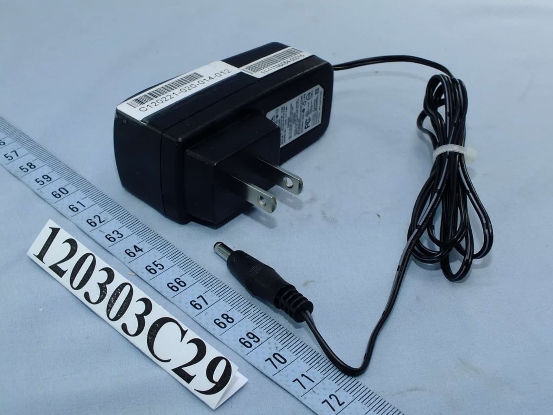
Click to zoom
Application Details
- Equipment Class
- DTS - Digital Transmission System
- Date of Grant
- Jul 11, 2012
- Application Purpose
- Original Equipment
- Date of Application
- Jul 11, 2012
- Equipment Note
- 802.11n Single-band Unified Access Point
- Frequency Range
- 2412.00000000 - 2462.00000000
- Company
- D-Link Corporation
- Country
- United States
Documents & Files
Document Text
Text extracted from the exhibit documents filed with the FCC. Open a document above to read the original.
Users Manual
Unified Access Point Administrator’s Guide Unified Access Point Administrator’s Guide Page 1 March 2012 Unified Access Point Administrator’s Guide Unified Access Point Administrator’s Guide Page 2 March 2012 Table of Contents Section 1 - About This Document ............................................................................................9 Document Organization .........................................................................................................................................9 Additional Documentation .....................................................................................................................................9 Document Conventions .........................................................................................................................................9 Online Help, Supported Browsers, and Limitations .............................................................................................10 Section 2 - Getting Started ......................................................................................................11 Administrator’s Computer Requirements ............................................................................................................11 Wireless Client Requirements .............................................................................................................................12 Dynamic and Static IP Addressing on the AP ......................................................................................................13 Recovering an IP Address .............................................................................................................................13 Discovering a Dynamically Assigned IP Address ..........................................................................................13 Installing the UAP ................................................................................................................................................13 Basic Settings ......................................................................................................................................................16 Connecting to the AP Web Interface by Using the IPv6 Address ..................................................................17 Using the CLI to View the IP Address..................................................................................................................17 Configuring the Ethernet Settings .......................................................................................................................18 Using the CLI to Configure Ethernet Settings ...............................................................................................18 Configuring IEEE 802.1X Authentication .............................................................................................................19 Using the CLI to Configure 802.1X Authentication Information .....................................................................20 Verifying the Installation ......................................................................................................................................20 Configuring Security on the Wireless Access Point .............................................................................................21 Section 3 - Viewing Access Point Status ...............................................................................22 Viewing Interface Status ......................................................................................................................................22 Wired Settings (Internal Interface) ................................................................................................................22 Wireless Settings ..........................................................................................................................................22 Viewing Events ....................................................................................................................................................23 Configuring Persistent Logging Options ........................................................................................................23 Configuring the Log Relay Host for Kernel Messages ..................................................................................24 Enabling or Disabling the Log Relay Host on the Events Page ....................................................................24 Viewing Transmit and Receive Statistics .............................................................................................................25 Viewing Associated Wireless Client Information .................................................................................................26 Viewing TSPEC Client Associations ....................................................................................................................26 Link Integrity Monitoring ................................................................................................................................28 Viewing Rogue AP Detection...............................................................................................................................28 Saving and Importing the Known AP List ......................................................................................................30 Viewing Managed AP DHCP Information ............................................................................................................31 Viewing TSPEC Status and Statistics Information ..............................................................................................31 Viewing TSPEC AP Statistics Information ...........................................................................................................32 Viewing Radio Statistics Information ........................................................................…
Text truncated - open the document above for the full version.
Users Manual
Unified Access Point Administrator’s Guide Unified Access Point Administrator’s Guide Page 61 March 2012 Section 4 - Managing the Access Point FieldDescription Load BalancingEnable or disable load balancing: To enable load balancing on this AP, click Enable. To disable load balancing on this AP, click Disable. Utilization for No New Associations Provide the percentage of network bandwidth utilization allowed on the radio before the AP stops accepting new client associations. The default is 0, which means that all new associations will be allowed regardless of the utilization rate. Table 32 - Load Balancing Note: After you configure the load balancing settings, you must click Apply to apply the changes and to save the settings. Changing some settings might cause the AP to stop and restart system processes. If this happens, wireless clients will temporarily lose connectivity. We recommend that you change AP settings when WLAN traffic is low. Managed Access Point Overview The UAP can operate in two modes: Standalone Mode or Managed Mode. In Standalone Mode, the UAP acts as an individual AP in the network, and you manage it by using the Administrator Web User Interface (UI), CLI, or SNMP. In Managed Mode, the UAP is part of the D-Link Unified Wired and Wireless System, and you manage it by using the D-Link Unified Wireless Switch. If an AP is in Managed Mode, the Administrator Web UI, Telnet, SSH, and SNMP services are disabled. On the UAP, you can configure the IP addresses of up to four D-Link Unified Wireless Switches that can manage it. In order to manage the AP, the switch and AP must discover each other. There are multiple ways for a switch to discover an AP. Adding the IP address of the switch to the AP while it is in Standalone Mode is one way to enable switch-to-AP discovery. Transitioning Between Modes Every 30 seconds, the D-Link Unified Wireless Switch sends a keepalive message to all of the access points it manages. Each AP checks for the keepalive messages on the SSL TCP connection. As long as the AP maintains communication with the switch through the keepalive messages, it remains in Managed Mode. If the AP does not receive a message within 45 seconds of the last keepalive message, the AP assumes the switch has failed and terminates its TCP connection to the switch, and the AP enters Standalone Mode. Once the AP transitions to Standalone Mode, it continues to forward traffic without any loss. The AP uses the configuration on the VAPs configured in VLAN Forwarding mode (the standard, non-tunneled mode). While the AP is in Standalone Mode, you can manage it by using the Web interface or the CLI (through Telnet or SSH). For any clients that are connected to the AP through tunneled VAPs, the AP sends disassociate messages and disables the tunneled VAPs. As long as the Managed AP Administrative Mode is set to Enabled, the AP starts discovery procedures. If the AP establishes a connection with a wireless switch, which may or may not be the same switch it was connected to before, the switch sends the AP its configuration and the AP sends the wireless switch information about all currently associated clients. After the configuration from the switch is applied, the AP radio(s) restart. Client traffic is briefly interrupted until the radio(s) are up and the clients are re-associated. Unified Access Point Administrator’s Guide Unified Access Point Administrator’s Guide Page 62 March 2012 Section 4 - Managing the Access Point Configuring Managed Access Point Settings To add the IP address of a D-Link Unified Wireless Switch to the AP, click the Managed Access Point tab under the Manage heading and update the fields shown in the table below. Figure 30 - Configure Managed AP Wireless Switch Parameters FieldDescription Managed AP Administrative Mode Click Enabled to allow the AP and switch to discover each other. If the AP successfully authenticates itself with a wireless switch, you will not be able to access the Administrator UI. Click Disabled to prevent the AP from contacting wireless switches. Switch IP Address (1-4) Enter the IP address of up to four wireless switches that can manage the AP. You can enter the IP address in dotted format or as an DNS name. You can view a list of wireless switches on your network that were configured by using a DHCP server. The AP attempts to contact Switch IP Address 1 first. Base IP PortThe starting IP port number used by the wireless feature (in a range of 10 consecutive port numbers). Only the first number in the range is configurable. The default value is 57775 (through 57784). Note: When the wireless Base IP Port number is changed on the switch, the wireless feature is automatically disabled and re-enabled. The new value is not sent as part of the global switch configuration in the cluster configuration distribution command; every switch in the cluster must be configured independently with the new Wireless IP port number. Note: When the wireless Base IP Port number is changed from its default value on the switch, it must also be changed on the Access Points. Pass PhraseSelect the Edit option and enter a passphrase to allow the AP to authenticate itself with the wireless switch. The passphrase must be between 8 and 63 characters. To remove the password, select Edit, delete the existing password, and then click Apply. You must configure the same passphrase on the switch. WDS Managed Mode Specify whether the AP will act as a Root AP or Satellite AP within the WDS group: •) Root AP — Acts as a bridge or repeater on the wireless medium and communicates with the switch via the wired link. •) Satellite AP — Communicates with the switch via a WDS link to the Root AP. This mode enables the Satellite AP to discover and establish WDS link with the Root AP. WDS Managed Ethernet Port Specify whether the Ethernet port is to be enabled or disabled when the AP becomes part of a WDS group. WDS Group Password Password for WPA2 Personal authentication used to establi…
Text truncated - open the document above for the full version.
Users Manual
Unified Access Point Administrator’s Guide Unified Access Point Administrator’s Guide Page 91 March 2012 Section 8 - Configuring Client Quality of Service (QoS) FieldDescription ACL TypeSelect the type of ACL to configure: •) IPv4 •) IPv6 •) MAC IPv4 and IPv6 ACLs control access to network resources based on Layer 3 and Layer 4 criteria. MAC ACLs control access based on Layer 2 criteria. ACL Rule Configuration ACL Name - ACL Type Select the ACL to configure with the new rule. The list contains all ACLs added in the ACL Configuration section. RuleTo configure a new rule to add to the selected ACL, select New Rule. To add an existing rule to an ACL or to modify a rule, select the rule number. When an ACL has multiple rules, the rules are applied to the packet or frame in the order in which you add them to the ACL. There is an implicit deny all rule as the final rule. ActionSpecifies whether the ACL rule permits or denies an action. •) When you select Permit, the rule allows all traffic that meets the rule criteria to enter or exit the AP (depending on the ACL direction you select). Traffic that does not meet the criteria is dropped. •) When you select Deny, the rule blocks all traffic that meets the rule criteria from entering or exiting the AP (depending on the ACL direction you select). Traffic that does not meet the criteria is forwarded unless this rule is the final rule. Because there is an implicit deny all rule at the end of every ACL, traffic that is not explicitly permitted is dropped. Match EveryIndicates that the rule, which either has a permit or deny action, will match the frame or packet regardless of its contents. If you select this field, you cannot configure any additional match criteria. The Match Every option is selected by default for a new rule. You must clear the option to configure other match fields. IPv4 ACL ProtocolSelect the Protocol field to use an L3 or L4 protocol match condition based on the value of the IP Protocol field in IPv4 packets or the Next Header field of IPv6 packets. Once you select the field, choose the protocol to match by keyword or enter a protocol ID. Select From List Select one of the following protocols from the list: •) IP •) ICMP •) IGMP •) TCP •) UDP Match to Value To match a protocol that is not listed by name, enter the protocol ID. The protocol ID is a standard value assigned by the IANA. The range is a number from 0–255. Source IP AddressSelect this field to require a packet’s source IP address to match the address listed here. Enter an IP address in the appropriate field to apply this criteria. Wild Card MaskSpecifies the source IP address wildcard mask. The wild card masks determines which bits are used and which bits are ignored. A wild card mask of 255.255.255.255 indicates that no bit is important. A wildcard of 0.0.0.0 indicates that all of the bits are important. This field is required when Source IP Address is checked. A wild card mask is, in essence, the inverse of a subnet mask. For example, To match the criteria to a single host address, use a wildcard mask of 0.0.0.0. To match the criteria to a 24-bit subnet (for example 192.168.10.0/24), use a wild card mask of 0.0.0.255. Unified Access Point Administrator’s Guide Unified Access Point Administrator’s Guide Page 92 March 2012 Section 8 - Configuring Client Quality of Service (QoS) FieldDescription Source PortSelect this field to include a source port in the match condition for the rule. The source port is identified in the datagram header. Once you select the field, choose the port name or enter the port number. Select From List Select the keyword associated with the source port to match: •) ftp •) ftpdata •) http •) smtp •) snmp •) telnet •) tftp •) www Each of these keywords translates into its equivalent port number. Match to Port Enter the IANA port number to match to the source port identified in the datagram header. The port range is 0 – 65535 and includes three different types of ports: •) 0 – 1023: Well Known Ports •) 1024 – 49151: Registered Ports •) 49152 – 65535: Dynamic and/or Private Ports Destination IP Address Select this field to require a packet’s destination IP address to match the address listed here. Enter an IP address in the appropriate field to apply this criteria. Wild Card MaskSpecifies the destination IP address wildcard mask. The wild card masks determines which bits are used and which bits are ignored. A wild card mask of 255.255.255.255 indicates that no bit is important. A wildcard of 0.0.0.0 indicates that all of the bits are important. This field is required when Source IP Address is checked. A wild card mask is in essence the inverse of a subnet mask. For example, To match the criteria to a single host address, use a wildcard mask of 0.0.0.0. To match the criteria to a 24-bit subnet (for example 192.168.10.0/24), use a wild card mask of 0.0.0.255. Destination PortSelect this field to include a destination port in the match condition for the rule. The destination port is identified in the datagram header. Once you select the field, choose the port name or enter the port number. Select From List Select the keyword associated with the destination port to match: •) ftp •) ftpdata •) http •) smtp •) snmp •) telnet •) tftp •) www Each of these keywords translates into its equivalent port number. Match to Port Enter the IANA port number to match to the destination port identified in the datagram header. The port range is 0 – 65535 and includes three different types of ports: •) 0 – 1023: Well Known Ports •) 1024 – 49151: Registered Ports •) 49152 – 65535: Dynamic and/or Private Ports IP DSCPTo use IP DSCP as a match criteria, select the check box and select a DSCP value keyword or enter a DSCP value to match. You can select only one service type (DSCP, IP Precedence or TOS bits) to use for match criteria. Select from List Select from a list of DSCP types. Match to Value Enter a DSCP Value to match (0 – 63). Unified Access Point Administrator’s Gu…
Text truncated - open the document above for the full version.
External Photos
Page 1 CONSTRUCTION PHOTOS OF EUT Page 2 Page 3 Page 4
Internal Photos
Page 5 Page 6 Page 7 Page 8
Operational Description
FCC ID: KA2WL2600APA1 Report No.: RF120303C29 Operational Description This device is an 802.11n Single-band Unified Access Point, which operates in 2.4GHz band; the maximum data rate could be up to 300Mbps which OFDM technique. If the signal to noise radio is too poor which could not support 300Mbps, the 11Mbps data rate with DSSS technique will be applied. The transmitter of the EUT is powered by 12Vdc power adapter or 55Vdc from PSE. The antenna is PIFA antenna with UFL antenna connector. For more detailed instruction, please take a look at the user’s manual.
RF Exposure Info
Report No.: SA120303C29 Report Format Version 4.0.0 1 RF EXPOSURE REPORT REPORT NO.: SA120303C29 MODEL NO.: DWL-2600AP FCC ID: KA2WL2600APA1 RECEIVED: Feb. 21, 2012 TESTED: Mar. 08 ~ Apr. 25, 2012 ISSUED: Apr. 27, 2012 APPLICANT: D-Link Corporation ADDRESS: 17595 Mt. Herrmann, Fountain Valley, California 92708, United States ISSUED BY: Bureau Veritas Consumer Products Services (H.K.) Ltd., Taoyuan Branch LAB ADDRESS: No. 47, 14th Ling, Chia Pau Vil., Lin Kou Dist., New Taipei City, Taiwan ( R.O.C. ) TEST LOCATION: No. 19, Hwa Ya 2nd Rd, Wen Hwa Tsuen, Kwei Shan Hsiang, Taoyuan Hsien 333, Taiwan, R.O.C. This test report consists of 5 pages in total. It may be duplicated completely for legal use with the approval of the applicant. It should not be reproduced, except in full, without the written approval of our laboratory. The client should not use it to claim product, certification, approval, or endorsement by any government agency. The test results in the report only apply to the tested sample. Report No.: SA120303C29 Report Format Version 4.0.0 2 TABLE OF CONTENTS RELEASE CONTROL RECORD ................................................................................................................ 3 1. CERTIFICATION ............................................................................................................................. 4 2. RF EXPOSURE ............................................................................................................................... 5 2.1 LIMITS FOR MAXIMUM PERMISSIBLE EXPOSURE (MPE) ........................................................ 5 2.2 MPE CALCULATION FORMULA .................................................................................................... 5 2.3 CLASSIFICATION ........................................................................................................................... 5 2.4 CALCULATION RESULT OF MAXIMUM CONDUCTED POWER ................................................. 5 Report No.: SA120303C29 Report Format Version 4.0.0 3 RELEASE CONTROL RECORD ISSUE NO. REASON FOR CHANGE DATE ISSUED SA120303C29 Original release Apr. 27, 2012 Report No.: SA120303C29 Report Format Version 4.0.0 4 1. CERTIFICATION PRODUCT: 802.11n Single-band Unified Access Point MODEL: DWL-2600AP BRAND: D-Link APPLICANT: D-Link Corporation TESTED: Mar. 08 ~ Apr. 25, 2012 TEST SAMPLE: ENGINEERING SAMPLE STANDARDS: FCC Part 2 (Section 2.1091) FCC OET Bulletin 65, Supplement C (01-01) IEEE C95.1 The above equipment (Model: DWL-2600AP) has been tested by Bureau Veritas Consumer Products Services (H.K.) Ltd., Taoyuan Branch, and found compliance with the requirement of the above standards. The test record, data evaluation & Equipment Under Test (EUT) configurations represented herein are true and accurate accounts of the measurements of the sample’s EMC characteristics under the conditions specified in this report. PREPARED BY : , DATE:Apr. 27, 2012 Polly Chien / Specialist APPROVED BY : , DATE:Apr. 27, 2012 Gary Chang / Technical Manager Report No.: SA120303C29 Report Format Version 4.0.0 5 2. RF EXPOSURE 2.1 LIMITS FOR MAXIMUM PERMISSIBLE EXPOSURE (MPE) FREQUENCY RANGE (MHz) ELECTRIC FIELD STRENGTH (V/m) MAGNETIC FIELD STRENGTH (A/m) POWER DENSITY (mW/cm 2 ) AVERAGE TIME (minutes) LIMITS FOR GENERAL POPULATION / UNCONTROLLED EXPOSURE 300-1500 ... ... F/1500 30 1500-100,000 ... ... 1.0 30 F = Frequency in MHz 2.2 MPE CALCULATION FORMULA Pd = (Pout*G) / (4*pi*r2) where Pd = power density in mW/cm2 Pout = output power to antenna in mW G = gain of antenna in linear scale Pi = 3.1416 R = distance between observation point and center of the radiator in cm 2.3 CLASSIFICATION The antenna of this product, under normal use condition, is at least 20cm away from the body of the user. So, this device is classified as Mobile Device. 2.4 CALCULATION RESULT OF MAXIMUM CONDUCTED POWER FREQUENCY BAND (MHz) MAX POWER (dBm) ANTENNA GAIN (dBi) DISTANCE (cm) POWER DENSITY (mW/cm 2 ) LIMIT (mW/cm 2 ) 2412-2462 26.6 3.2 20 0.190 1
Test Report
Report No.: RF120303C29 1 Report Format Version 4.2.0 FCC TEST REPORT REPORT NO.: RF120303C29 MODEL NO.: DWL-2600AP FCC ID: KA2WL2600APA1 RECEIVED: Feb. 21, 2012 TESTED: Mar. 08 ~ Apr. 25, 2012 ISSUED: Apr. 27, 2012 APPLICANT: D-Link Corporation ADDRESS: 17595 Mt. Herrmann, Fountain Valley, California 92708, United States ISSUED BY: Bureau Veritas Consumer Products Services (H.K.) Ltd., Taoyuan Branch LAB ADDRESS: No. 47, 14th Ling, Chia Pau Vil., Lin Kou Dist., New Taipei City, Taiwan ( R.O.C. ) TEST LOCATION: No. 19, Hwa Ya 2nd Rd, Wen Hwa Tsuen, Kwei Shan Hsiang, Taoyuan Hsien 333, Taiwan, R.O.C. This test report consists of 65 pages in total. It may be duplicated completely for legal use with the approval of the applicant. It should not be reproduced except in full, without the written approval of our laboratory. The client should not use it to claim product, certification, approval or endorsement by TAF or any government agency. The test results in the report only apply to the tested sample. Report No.: RF120303C29 2 Report Format Version 4.2.0 TABLE OF CONTENTS RELEASE CONTROL RECORD ................................................................................................................ 4 1. CERTIFICATION ........................................................................................................................... 5 2. SUMMARY OF TEST RESULTS ................................................................................................... 6 2.1 MEASUREMENT UNCERTAINTY ................................................................................................ 6 3. GENERAL INFORMATION ........................................................................................................... 7 3.1 GENERAL DESCRIPTION OF EUT .............................................................................................. 7 3.2 DESCRIPTION OF TEST MODES ................................................................................................ 9 3.2.1 TEST MODE APPLICABILITY AND TESTED CHANNEL DETAIL ............................................. 10 3.3 DESCRIPTION OF SUPPORT UNITS ........................................................................................ 12 3.3.1 CONFIGURATION OF SYSTEM UNDER TEST ......................................................................... 13 3.4 GENERAL DESCRIPTION OF APPLIED STANDARDS ............................................................. 14 4. TEST TYPES AND RESULTS ..................................................................................................... 15 4.1 RADIATED EMISSION AND BANDEDGE MEASUREMENT ..................................................... 15 4.1.1 LIMITS OF RADIATED EMISSION AND BANDEDGE MEASUREMENT .................................. 15 4.1.2 TEST INSTRUMENTS ................................................................................................................ 16 4.1.3 TEST PROCEDURES ................................................................................................................. 17 4.1.4 DEVIATION FROM TEST STANDARD ....................................................................................... 17 4.1.5 TEST SETUP .............................................................................................................................. 18 4.1.6 EUT OPERATING CONDITIONS ................................................................................................ 18 4.1.7 TEST RESULTS .......................................................................................................................... 19 4.2 CONDUCTED EMISSION MEASUREMENT .............................................................................. 39 4.2.1 LIMITS OF CONDUCTED EMISSION MEASUREMENT ........................................................... 39 4.2.2 TEST INSTRUMENTS ................................................................................................................ 39 4.2.3 TEST PROCEDURES ................................................................................................................. 40 4.2.4 DEVIATION FROM TEST STANDARD ....................................................................................... 40 4.2.5 TEST SETUP .............................................................................................................................. 41 4.2.6 EUT OPERATING CONDITIONS ................................................................................................ 41 4.2.7 TEST RESULTS .......................................................................................................................... 42 4.3 6dB BANDWIDTH MEASUREMENT .......................................................................................... 46 4.3.1 LIMITS OF 6dB BANDWIDTH MEASUREMENT ....................................................................... 46 4.3.2 TEST SETUP .............................................................................................................................. 46 4.3.3 TEST INSTRUMENTS ................................................................................................................ 46 4.3.4 TEST PROCEDURE ................................................................................................................... 46 4.3.5 DEVIATION FROM TEST STANDARD ....................................................................................... 46 4.3.6 EUT OPERATING CONDITIONS ................................................................................................ 46 4.3.7 TEST RESULTS .......................................................................................................................... 47 4.4 CONDUCTED OUTPUT POWER ............................................................................................... 49 4.4.1 LIMITS OF CONDUCTED OUTPUT POWER MEASUREMENT ............................................... 49 4.4.2 TEST SETUP ....…
Text truncated - open the document above for the full version.
Test Setup Photos
1 PHOTOGRAPHS OF THE TEST CONFIGURATION CONDUCTED EMISSION TEST TEST MODE A 2 CONDUCTED EMISSION TEST TEST MODE B 3 RADIATED EMISSION TEST TEST MODE A 4 RADIATED EMISSION TEST TEST MODE B
Contact Information
Applicant
Brett Adair(General Counsel)
Technical Contact
Bureau Veritas CPS (H.K.) Ltd. Taoyuan BranchGary Chang
[email protected]886-3-3183232
No. 19, Hwa Ya 2nd Rd., Kwei Shan Hsiang · Taoyuan Hsien · Taiwan
Non-Technical Contact
Bureau Veritas CPS (H.K.) Ltd. Taoyuan BranchCeline Chou
[email protected]886-3-3183232
Test Firm
Bureau Veritas CPS (H.K.) Ltd. Taoyuan BranchRichard Chen
Technical Specifications
| # | Rule Parts | Frequency Range | Power Output |
|---|---|---|---|
| 1 | 15C | 2.41 GHz - 2.46 GHz | 459.00 mW |
Other Applications from D-Link Corporation

KA2CS6012A1
Jul 07, 20262K Fixed Indoor Cloud Camera, 2K Fixed Indoor Wi-Fi Camera
Equipment Class
DTS - Digital Transmission SystemKA2AE65UA1
Mar 02, 2026Wi-Fi 7 BE6500 USB 3.0 Dongle
Equipment Class
NII - Unlicensed National Information Infrastructure TXKA2APE9560A1
Nov 17, 2025BE9500 Celling mount Access Point
Equipment Class
6ID - 15E 6 GHz Low Power Indoor Access PointKA2AX9UA1
Dec 04, 2024AX900 Wi-Fi 6 USB Adapter, Wi-Fi 6 AX900 USB 2.0 Dongle
Equipment Class
DSS - Part 15 Spread Spectrum TransmitterKA2AC13UA1
Dec 04, 2024AC1300 Wi-Fi 5 USB Adapter, Wi-Fi 5 AC1300 USB 2.0 Dongle
Equipment Class
DTS - Digital Transmission System