KA2WM158B1HSPA+ USB ADAPTER
D-Link Corporation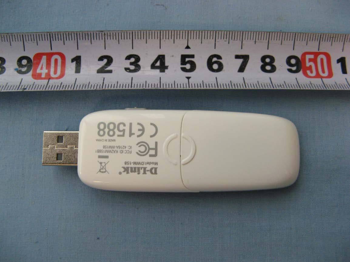
Click to zoom
Application Details
- Equipment Class
- PCB - PCS Licensed Transmitter
- Date of Grant
- Jun 01, 2010
- Application Purpose
- Original Equipment
- Date of Application
- May 30, 2010
- Equipment Note
- HSPA+ USB ADAPTER
- Frequency Range
- 1852.40000000 - 1907.60000000
- Company
- D-Link Corporation
- Country
- United States
Documents & Files
Document Text
Text extracted from the exhibit documents filed with the FCC. Open a document above to read the original.
Users Manual
1 HSPA+ USB Modem User Manual 2 Contents 1 Modem Introduction ......................................................... 4 1.1 Introduction .......................................................................................... 4 1.2 Warning and Notice ............................................................................. 4 1.3 Applicability Scope .............................................................................. 6 1.4 System requirements ........................................................................... 7 1.5 Functions ............................................................................................. 7 1.6 Specification ........................................................................................ 7 2 Installation ......................................................................... 9 2.1 Outline and Parts ................................................................................. 9 2.2 Hardware Installation ........................................................................... 9 2.3 Software Installation .......................................................................... 11 2.4 Run the Application Software ............................................................ 15 2.5 Hardware Uninstall ............................................................................ 16 2.6 Software Uninstall .............................................................................. 16 3 Functions & Operation ................................................... 19 3.1 Interface introduction ......................................................................... 19 3.1.1 Main Interface ......................................................................... 19 3.1.2 Description of Mini Icons ........................................................ 20 3.2 Connecting to the Internet ................................................................. 21 3.3 SMS ................................................................................................... 22 3.3.1 Check SMS............................................................................. 23 3.3.2 Create a new message........................................................... 24 3.3.3 The SMS box operating guide ................................................ 26 3.4 USB modembook .............................................................................. 26 3.5 Settings .............................................................................................. 28 3.5.1 Connection settings ................................................................ 29 3.5.2 Selection settings ................................................................... 31 3.5.3 Preference settings................................................................. 31 3.5.4 SMS Settings .......................................................................... 32 3.5.5 Sound settings ........................................................................ 33 3.5.6 Security settings ..................................................................... 33 3 3.5.7 System settings ...................................................................... 34 3.5.8 Update settings....................................................................... 34 3.6 Data record ........................................................................................ 35 3.7 MicroSD card ..................................................................................... 35 3.8 Help ................................................................................................... 35 4 FAQ ................................................................................... 36 4 1 Modem Introduction 1.1 Introduction Thank you for purchasing DWM-158 HSPA+ USB Modem. To guarantee that the modem is always in its best condition, please read this manual carefully and keep it for further use. The pictures, symbols and contents in this manual are just for your reference. They might not be completely identical with your modem. ZTE operates a policy of continuous development and reserves the right to update the technical specifications in this document at any time without prior notice. The DWM-158 HSPA+ USB Modem is a type of multi-mode, 3G modem, suitable for GSM/GPRS/EDGE/UMTS/HSDPA/HSUPA/HSPA+ networks. With a USB interface connecting to a laptop or a desktop PC, it integrates the functionality of a modem and a mobile USB modem (SMS and USB modembook), combining mobile communication with internet perfectly. While connected to the mobile network, it can help you get SMS, data service and will help you break away from the limit of time and space, and realize wireless communication at any moment everywhere. 1.2 Warning and Notice To the owner The use of electronic transmitting devices is forbidden in aircraft, at petrol stations and in hospitals. Please observe and obey all warning signs and switch off your modem in these conditions. Operating USB modem may interfere with medical devices like hearing aides and pacemakers. Be aware of warning signs in places such as oil refineries or chemical factories where there are explosive gases or explosive products being processed. Store the USB modem out of the reach of children. The USB modem may cause injury if used as a toy or may be damaged by rough play or moisture. Do not open the cover and touch the metallic (U)SIM bracket when the modem is working. Otherwise, you may get a burn. Modem The USB modem must only be used with a PC that is certified to IEC 60950-1 (or equivalent) or a PC that has a power supply that is certified to IEC 60950-1 (or equivalent) or a PC that is powered by an internal battery and that has no connection to mains power. 5 Only use original accessories supplied by the manufacturer. Using unauthorised accessories may invalidate your warranty. Avoid using the USB modem near or inside metallic structures or establishments that can emit…
Text truncated - open the document above for the full version.
External Photos
External Photos:
ID Label/Location Info
FCC_IC Label Placement: Label
Internal Photos
Internal Photos:
RF Exposure Info
Report No.: RZA2010-0676 TESTING No. L2264 OET 65 TEST REPORT Product Name HSPA+ USB ADAPTER Model DWM-158 FCC ID KA2WM158B1 IC ID 4216A-WM158 Client D-Link Corporation TA Technology (Shanghai) Co., Ltd. GENERAL SUMMARY Product Name HSPA+ USB ADAPTER Model DWM-158 FCC ID KA2WM158B1 IC ID 4216A-WM158 Report No. RZA2010-0676 Client D-Link Corporation Manufacturer D-Link Corporation Reference Standard(s) IEEE Std C95.1, 1999: IEEE Standard for Safety Levels with Respect to Human Exposure to Radio Frequency Electromagnetic Fields, 3 kHz to 300 GHz. SUPPLEMENT C Edition 01-01 to OET BULLETIN 65 Edition 97-01 June 2001 including DA 02-1438, published June 2002: Evaluating Compliance with FCC Guidelines for Human Exposure to Radio frequency Electromagnetic Fields Additional Information for Evaluation Compliance of Mobile and Portable Devices with FCC Limits for Human Exposure to Radio frequency Emissions. KDB 447498 D02(2009-11-13): SAR Measurement Procedures for USB Dongle Transmitters. RSS-102 Issue 4 March 2010: Radio Frequency (RF) Exposure Compliance of Radiocommunication Apparatus (All Frequency Bands). Conclusion This portable wireless equipment has been measured in all cases requested by the relevant standards. Test results in Chapter 7 of this test report are below limits specified in the relevant standards. General Judgment: Pass (Stamp) Date of issue: May 27 th , 2010 Comment The test result only responds to the measured sample. Approved by Yang Weizhong Revised by Ling Minbao Performed by Xue Chaofeng TA Technology (Shanghai) Co., Ltd. Test Report Report No. RZA2010-0676 Page 3 of 111 TABLE OF CONTENT 1. General Information ........................................................................................................................ 5 1.1. Notes of the test report............................................................................................................ 5 1.2. Testing laboratory .................................................................................................................... 5 1.3. Applicant Information ............................................................................................................... 6 1.4. Manufacturer Information ......................................................................................................... 6 1.5. Information of EUT................................................................................................................... 7 1.6. Test Date ................................................................................................................................. 8 2. Operational Conditions during Test ................................................................................................. 9 2.1. General description of test procedures .................................................................................... 9 2.2. GSM Test Configuration ........................................................................................................... 9 2.3. WCDMA Test Configuration ................................................................................................... 10 2.4. HSDPA Test Configuration ..................................................................................................... 10 2.5. HSUPA Test Configuration ..................................................................................................... 12 2.6. Position of module in Portable devices .................................................................................. 14 2.7. Picture of host product ........................................................................................................... 15 3. SAR Measurements System Configuration ................................................................................... 17 3.1. SAR Measurement Set-up .....................................................................................................17 3.2. DASY4 E-field Probe System ................................................................................................ 18 3.2.1. EX3DV4 Probe Specification .......................................................................................... 18 3.2.2. E-field Probe Calibration ................................................................................................. 19 3.3. Other Test Equipment ............................................................................................................19 3.3.1. Device Holder for Transmitters ....................................................................................... 19 3.3.2. Phantom .........................................................................................................................20 3.4. Scanning procedure............................................................................................................... 20 3.5. Data Storage and Evaluation ................................................................................................. 22 3.5.1. Data Storage...................................................................................................................22 3.5.2. Data Evaluation by SEMCAD ......................................................................................... 22 3.6. System check......................................................................................................................... 25 3.7. Equivalent Tissues ................................................................................................................. 26 4. Laboratory Environment................................................................................................................ 26 5. Characteristics of the Test ............................................................................................................. 27 5.1. Applicable Limit Regulations ..............................................................................................…
Text truncated - open the document above for the full version.
Test Report
No.2010TAR184 Page1 of 75 TEST REPORT No. 2010TAR184 for D-Link Corporation HSPA+ USB ADAPTER Type:DWM-158 With FCC ID: KA2WM158B1 IC ID: 4216A-WM158 Hardware Version: B1 Software Version: DWM_158_v2.00TLCAN Issued Date: 2010-06-01 Note: The test results in this test report relate only to the devices specified in this report. This report shall not be reproduced except in full without the written approval of TMC Beijing. Test Laboratory: DAR accreditation (DIN EN ISO/IEC 17025): No. DGA-PL-114/01-02 FCC 2.948 Listed: No.733176 IC O.A.T.S listed: No.6629A-1 TMC Beijing, Telecommunication Metrology Center of Ministry of Industry and Information Technology No. 52, Huayuan Bei Road, Haidian District, Beijing, P. R. China 100191. Tel:+86(0)10-62304633, Fax:+86(0)10-62304633 Email:[email protected]. www.emcite.com No.2010TAR184 Page2 of 75 CONTENTS 1. TEST LABORATORY .............................................................................................................. 3 1.1. TESTING LOCATION .......................................................................................................... 3 1.2. TESTING ENVIRONMENT .................................................................................................. 3 1.3. PROJECT DATA .................................................................................................................. 3 1.4. SIGNATURE ........................................................................................................................ 3 2. CLIENT INFORMATION .......................................................................................................... 4 2.1. APPLICANT INFORMATION............................................................................................... 4 2.2. MANUFACTURER INFORMATION ..................................................................................... 4 3. EQUIPMENT UNDER TEST (EUT) AND ANCILLARY EQUIPMENT (AE) ............................ 5 3.1. ABOUT EUT ........................................................................................................................ 5 3.2. INTERNAL IDENTIFICATION OF EUT USED DURING THE TEST ................................... 5 3.3. GENERAL DESCRIPTION .................................................................................................. 5 3.4. EMISSION DESIGNATOR ................................................................................................... 5 EMISSION DESIGNATOR .............................................................................................................. 5 4. REFERENCE DOCUMENTS .................................................................................................. 6 4.1. REFERENCE DOCUMENTS FOR TESTING ...................................................................... 6 5. LABORATORY ENVIRONMENT ............................................................................................ 7 6. SUMMARY OF TEST RESULTS ............................................................................................. 8 7. TEST EQUIPMENTS UTILIZED .............................................................................................. 8 ANNEX A: MEASUREMENT RESULTS ........................................................................................ 9 A.1 OUTPUT POWER ............................................................................................................... 9 A.2 EMISSION LIMT ............................................................................................................... 14 A.3 RECEIVER RADIATION EMISSION .......................................................................................... 29 A.4 FREQUENCY STABILITY ................................................................................................. 33 A.5 OCCUPIED BANDWIDTH (§2.1049(H)(I)) ..................................................................... 35 A.6 EMISSION BANDWIDTH (§22.917(B)/§24.238(B)) ...................................................... 47 A.7 BAND EDGE COMPLIANCE (§22.917(B)/§24.238(B)) ................................................. 59 A.8 CONDUCTED SPURIOUS EMISSION (§2.1057/§22.917/§24.238) .............................. 65 No.2010TAR184 Page3 of 75 1. Test Laboratory 1.1. Testing Location Company Name: TMC Beijing, Telecommunication Metrology Center of MIIT Address: No 52, Huayuan beilu, Haidian District, Beijing,P.R.China Postal Code: 100191 Telephone: 00861062304633 Fax: 00861062304793 1.2. Testing Environment Normal Temperature: 15-35°C Relative Humidity: 20-75% 1.3. Project data Testing Start Date: 2010-05-12 Testing End Date: 2010-06-01 1.4. Signature Zi Xiaogang (Prepared this test report) Sun Xiangqian (Reviewed this test report) Lu Bingsong Deputy Director of the laboratory (Approved this test report) No.2010TAR184 Page4 of 75 2. Client Information 2.1. Applicant Information Company Name: D-Link Corporation Address /Post: No.289, Sinhu 3rd Rd., Neihu District, Taipei City 114, Taiwan City: Taipei Country: China Telephone: 02-66000123 ext 5834 Fax: 02-55509988 2.2. Manufacturer Information Company Name: D-Link Corporation Address /Post: No.289, Sinhu 3rd Rd., Neihu District, Taipei City 114, Taiwan City: Taipei Country: China Telephone: 02-66000123 ext 5834 Fax: 02-55509988 Company Name: D-Link Corporation No.2010TAR184 Page5 of 75 3. Equipment Under Test (EUT) and Ancillary Equipment (AE) 3.1. About EUT Description HSPA+ USB ADAPTER Model Name DWM-158 FCC ID KA2WM158B1 IC 4216A-WM158 Frequency GSM 850MHz; PCS 1900MHz;EGSM900;DCS1800;WCDMA Band I/II/V Antenna Internal Power supply USB Output power 24.70 dBm maximum ERP measured for GSM850 Extreme vol. Limits 4.8VDC to 5.2VDC (nominal: 5.0VDC) Extreme temp. Tolerance -30°C to +50°C Note: Components list, please refer to documents of the manufacturer; it is also included in the original test record of Telecommunication Metrology Center of MIIT of People’s Republic of China. 3.2. Interna…
Text truncated - open the document above for the full version.
Test Report
No.2010TAR185 Page1 of 51 TEST REPORT No. 2010TAR185 for D-Link Corporation HSPA+ USB ADAPTER Type:DWM-158 With FCC ID: KA2WM158B1 IC ID: 4216A-WM158 Hardware Version: B1 Software Version: DWM_158_v2.00TLCAN Issued Date: 2010-06-01 Note: The test results in this test report relate only to the devices specified in this report. This report shall not be reproduced except in full without the written approval of TMC Beijing. Test Laboratory: DAR accreditation (DIN EN ISO/IEC 17025): No. DGA-PL-114/01-02 FCC 2.948 Listed: No.733176 IC O.A.T.S listed: No.6629A-1 TMC Beijing, Telecommunication Metrology Center of Ministry of Industry and Information Technology No. 52, Huayuan Bei Road, Haidian District, Beijing, P. R. China 100191. Tel:+86(0)10-62304633, Fax:+86(0)10-62304633 Email:[email protected]. www.emcite.com No.2010TAR185 Page2 of 51 CONTENTS 1. TEST LABORATORY ......................................................................................................................... 3 1.1. TESTING LOCATION .................................................................................................................... 3 1.2. TESTING ENVIRONMENT ........................................................................................................... 3 1.3. PROJECT DATA .............................................................................................................................. 3 1.4. SIGNATURE ..................................................................................................................................... 3 2. CLIENT INFORMATION ................................................................................................................... 4 2.1. APPLICANT INFORMATION ....................................................................................................... 4 2.2. MANUFACTURER INFORMATION ............................................................................................ 4 3. EQUIPMENT UNDER TEST (EUT) AND ANCILLARY EQUIPMENT (AE) ............................. 5 3.1. ABOUT EUT ..................................................................................................................................... 5 3.2. INTERNAL IDENTIFICATION OF EUT USED DURING THE TEST .................................... 5 3.3. GENERAL DESCRIPTION ............................................................................................................ 5 3.4. EMISSION DESIGNATOR ............................................................................................................. 5 EMISSION DESIGNATOR ......................................................................................................................... 5 4. REFERENCE DOCUMENTS ............................................................................................................. 6 4.1. REFERENCE DOCUMENTS FOR TESTING ............................................................................. 6 5. LABORATORY ENVIRONMENT ..................................................................................................... 7 6. SUMMARY OF TEST RESULTS ....................................................................................................... 8 7. TEST EQUIPMENTS UTILIZED ...................................................................................................... 8 ANNEX A: MEASUREMENT RESULTS .................................................................................................. 9 A.1 OUTPUT POWER ............................................................................................................................. 9 A.2 EMISSION LIMT ............................................................................................................................ 12 A.3 RECEIVER RADIATION EMISSION ...................................................................................................... 27 A.4 FREQUENCY STABILITY ............................................................................................................ 31 A.5 OCCUPIED BANDWIDTH (§2.1049(H)(I)) ................................................................................. 33 A.6 EMISSION BANDWIDTH (§22.917(B)/§24.238(B)) .................................................................. 37 A.7 BAND EDGE COMPLIANCE .......................................................................................................... 41 A.8 CONDUCTED SPURIOUS EMISSION (§2.1057/§22.917/§24.238) ............................................... 43 No.2010TAR185 Page3 of 51 1. Test Laboratory 1.1. Testing Location Company Name: TMC Beijing, Telecommunication Metrology Center of MIIT Address: No 52, Huayuan beilu, Haidian District, Beijing,P.R.China Postal Code: 1000191 Telephone: 00861062304633 Fax: 00861062304793 1.2. Testing Environment Normal Temperature: 15-35°C Relative Humidity: 20-75% 1.3. Project data Testing Start Date: 2010-05-12 Testing End Date: 2010-06-01 1.4. Signature Zi Xiaogang (Prepared this test report) Sun Xiangqian (Reviewed this test report) Lu Bingsong Deputy Director of the laboratory (Approved this test report) No.2010TAR185 Page4 of 51 2. Client Information 2.1. Applicant Information Company Name: D-Link Corporation Address /Post: No.289, Sinhu 3rd Rd., Neihu District, Taipei City 114, Taiwan City: Taipei Country: China Telephone: 02-66000123 ext 5834 Fax: 02-55509988 2.2. Manufacturer Information Company Name: D-Link Corporation Address /Post: No.289, Sinhu 3rd Rd., Neihu District, Taipei City 114, Taiwan City: Taipei Country: China Telephone: 02-66000123 ext 5834 Fax: 02-55509988 No.2010TAR185 Page5 of 51 3. Equipment Under Test (EUT) and Ancillary Equipment (AE) 3.1. About EUT Description HSPA+ USB ADAPTER Model Name DWM-158 FCC ID KA2WM158B1 IC 4216A-WM158 Frequency GSM 850MHz; PCS 1900MHz;EGSM900;DCS1800;WCDMA Band I/II/V Antenna Internal Power supply USB Output power 17.40 dBm maximum EIRP measured for WCDMA BandII Extreme vol. Limits 4…
Text truncated - open the document above for the full version.
Test Setup Photos
Te s t s e t-up photos: Part22/24 Radiated Spurious Emission
Test Setup Photos
TA Technology (Shanghai) Co., Ltd. Test Report Report No. RZA2010-0676 Page 109 of 111 ANNEX H: The EUT Appearances and Test Configuration Picture 5: Constituents of the EUT TA Technology (Shanghai) Co., Ltd. Test Report Report No. RZA2010-0676 Page 110 of 111 Picture 6: Test position 1 Picture 7: Test position 2 5mm 5mm TA Technology (Shanghai) Co., Ltd. Test Report Report No. RZA2010-0676 Page 111 of 111 Picture 8: Test Position 3 Picture 9: Test Position 4 5mm 5mm
Contact Information
Applicant
Brett Adair(General Counsel)
Technical Contact
Telecommunications Metrology Center of MIITXue Zhen
[email protected]+86-10-62304633
Floor 3, Shouxiang Science Building, No51, Xueyuan · Beijing · China
Test Firm
TMC-Telecommunication Metrology Center of M.I.I.TChongwen Song
Technical Specifications
| # | Rule Parts | Frequency Range | Power Output | Emission | Tolerance |
|---|---|---|---|---|---|
| 6 | 24E | 1.85 GHz - 1.91 GHz | 29.00 mW | 4M50F9W | 0.1 ppm |
Other Applications from D-Link Corporation

KA2CS6012A1
Jul 07, 20262K Fixed Indoor Cloud Camera, 2K Fixed Indoor Wi-Fi Camera
Equipment Class
DTS - Digital Transmission SystemKA2AE65UA1
Mar 02, 2026Wi-Fi 7 BE6500 USB 3.0 Dongle
Equipment Class
NII - Unlicensed National Information Infrastructure TXKA2APE9560A1
Nov 17, 2025BE9500 Celling mount Access Point
Equipment Class
6ID - 15E 6 GHz Low Power Indoor Access PointKA2AX9UA1
Dec 04, 2024AX900 Wi-Fi 6 USB Adapter, Wi-Fi 6 AX900 USB 2.0 Dongle
Equipment Class
DSS - Part 15 Spread Spectrum TransmitterKA2AC13UA1
Dec 04, 2024AC1300 Wi-Fi 5 USB Adapter, Wi-Fi 5 AC1300 USB 2.0 Dongle
Equipment Class
DTS - Digital Transmission System