KA2WM221B14G LTE USB ADAPTER
D-Link Corporation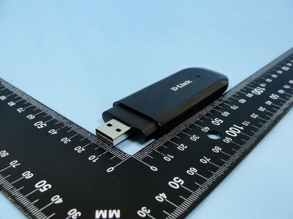
Click to zoom
Application Details
- Equipment Class
- PCB - PCS Licensed Transmitter
- Date of Grant
- Apr 29, 2014
- Application Purpose
- Original Equipment
- Date of Application
- Apr 28, 2014
- Equipment Note
- 4G LTE USB ADAPTER
- Frequency Range
- 2510.00000000 - 2560.00000000
- Company
- D-Link Corporation
- Country
- United States
Documents & Files
Document Text
Text extracted from the exhibit documents filed with the FCC. Open a document above to read the original.
Users Manual
DWM-221 User Manual Index LTE USB Adapter Introduction ....................................... 2 Internet service .............................................................. 5 SMS service .................................................................... 6 Contacts ....................................................................... 10 USSD ............................................................................. 13 STATISTICS .................................................................... 14 Settings ........................................................................ 15 FAQs ............................................................................. 20 LTE USB ADAPTER INTRODUCTION 1. To launch the Network Connect, double-click the shortcut icon on the desktop. It should be noted that: If the PIN code enabled, enter the correct one, then click OK. The (U)SIM will be locked after three retries of incorrect PIN code inputting; Enter the correct PUK to retrieve the default PIN code. After ten retries of incorrect PUK code inputting, please contact with your service provider; With the wrong PIN and PUK, all the network services are unavailable. 2. Main interface introduction : Connection : Access to the Text Message : Access to the Phonebook interface : Access to USSD : Access to check usage statistics : Set parameters options : Help (User Manual) 3. Status information Status Description New message New message(s) arrived. Message full Indicates the (U)SIM’s storage of SMS is full. No device Indicates that system cannot find the device. Initializing Indicates that the device is in the process of initializing. Searching The device is searching for the network. No service No suitable network. No (U)SIM card (U)SIM card not inserted or the device cannot recognized the (U)SIM. Invalid (U)SIM card The (U)SIM is out of service. Network signal Indicate the signal strength of the network. Network type GSM/GPRS, UMTS, LTE Data service EDGE available,HSUPA available, HSPA+ available. 4. LED Indicator description State of LED indicator Description RED Solid On No SIM card/ Error Green Solid On Register to network (not connect) Green blinking Connected to network *Green blinking: Flash once every 0.5 seconds) INTERNET SERVICE 1. Connecting with the default connection profile Click to set up the connection; 2. Statistics information The following window will be displayed at lower right corner of main interface when connecting to the internet. 3. Disconnect from the internet Click to disconnect the internet connection. SMS SERVICE Click to enter SMS ( Short Message Service) service interface. 1. Creating and sending a message. Click : Input the recipient number by one of the following options: Enter the number directly; Click Send to, choose the recipient number from the phonebook and add to the sending list, then click OK. Enter the message content; Click Send or Save to Draft. The message will be saved in the Draft when failed to send. Note: You can group send a message at most 100 recipients; Each number should be separated by “,”; The message cannot expand 1,530 characters at most. 2. Inbox The following prompt box will be displayed when received a new message; Reply: Access the edit interface, write the content, click Send or Save to D raft; Forward: Forward the selected message; Delete: Delete the selected message. Note: The new message will be saved in PC when Connection Manager running only, else in (U)SIM instead; You can use “Shift” or “Ctrl” to selected several messages; 3. Outbox The message in the Outbox can be deleted or forwarded. 4. Draft The MSG sent unsuccessfully will be saved in the Draft. Click the selected message; Confirm the recipient and the content, and click Send or Save to D raft. 5. Recycle All deleted information will be saved in the Recycle. 6. The selected SMS can be operated as follows: Save number: To save the sender’s information to the (U)SIM card or PC. Delete text message: To delete the selected message. Move to: To move the selected message to Outbox or Draft. Copy to: To copy the selected message to Outbox or Draft. SMS Export Right-click the selected the message; Click SMS Export ; Specify the path and the file name, and click Save. Note: The exported message will be saved as a *.csv file. C ONTACTS Click to enter Contacts interface. 1. New Click ; Enter the Name and Mobile, and save it in the (U)SIM card or PC. 2. Searching a contact Click; Enter the key characters of you want to find in the ; The result will be displayed in turn. 3. Viewing a contact Click Local or (U)SIM to display the contacts interface accordingly; Select a contact, then you can operate as follows: Edit: Modify the selected contact; Delete: Delete the selected contact; Send SMS: Send a message to the selected contact; Copy to: Copy the contact between (U)SIM card and PC. Note: The deleted contact information cannot be retrieved. 4. Import Right-click the mouse; Click Contacts Import; Select the *.vcf or *.csv file and click Open; The import file will be saved in the current interface. 5. Export Right-click the selected contact; Click Contacts Export; You can saved the contact file as *.csv file or *.vcf file; Confirm the name and the path the file saved, then click Save. USSD Click to enter USSD interface. You can add, edit, delete, and send USSD operation. The result of sending will display on the edit box. S TATISTICS Click to enter STATISTICS interface. View various connection statistics. SETTINGS Click to list the functions. 1. PIN Management Enable PIN Click Enable PIN; Enter the correct PIN code and click OK. Note: The PIN code should be a numeric string of 4-8 digits. Disable PIN Click Disable PIN; Enter the correct PIN code and click OK. Modify PIN Click Modify PIN; Enter the old PIN code and new PIN code, confirm the new PIN code and click OK. 2. Op…
Text truncated - open the document above for the full version.
Users Manual
COUNTRIES IN WHICH D-LINK LIMITED WARRANTY APPLIES PAÍSES NOS QUAIS A GARANTIA LIMITADA DA D-LINK SE APLICA LIMITED HARDWARE WARRANTY GARANTIA LIMITADA GARANTIA DE HARDWARE LIMITADA GARANTIA LIMITADA DO SOFTWARE O QUE NÃO ESTÁ COBERTO AVISO DE ISENÇÃO DE RESPONSABILIDADE O QUE VOCÊ DEVE FAZER PARA O SERVIÇO DE GARANTIA LIMITED SOFTWARE WARRANTY WHAT YOU MUST DO FOR WARRANTY SERVICE WHAT IS NOT COVERED DISCLAIMER LIMITATION OF LIABILITY GOVERNING LAW LIMITED HARDWARE WARRANTY WARRANTY & SAFETY INFORMATION LIMITED PRODUCT WARRANTY INFORMAÇÕES DE GARANTIA For better service, please register your product online at http://register.dlink.com D-Link provides Limited Warranty for its product only to the person or entity that originally purchased the product from D-Link or its authorized reseller or distributor. D-Link will fulfill the warranty obligations according to the local warranty policy of the country where you purchased your D-Link product. The warranty period starts on the date of purchase from D-Link or its authorized reseller or distributor. You may be required to provide a proof of purchase as a condition of receiving a warranty service. Your sales or delivery receipt, showing the date of purchase of the product, is your proof of purchase. You are entitled to warranty service if required within the warranty period under the terms and conditions of this document. Warranty Period Table The warranty periods stated in this table supersede and replace the warranty periods stated in the user’s manuals for relevant products. The Limited Warranty terms herein apply to countries in Asia, Oceania, Latin America and Africa, with exception to following countries, a. For Estonia, Latvia, Lithuania, Israel and Turkey, the general warranty period shall be two (2) years. b. For Russia, Ukraine, Belarus, Kazakhstan, Uzbekistan, Armenia, Azerbaijan, Moldova, Turkmenistan, Tajikistan and Kyrgyzstan, please refer to the last pages of this hardcopy warranty booklet in Russian. c. For Mongolia, please refer to the detail warranty in English at www.dlink.ru/mn. d. For the countries above, the Limited Lifetime Warranty information of DFL series firewalls, managed and smart switches can be seen at www.dlink.ru. For a detailed country list, please see D-Link website http://warranty.dlink. com. For the countries not on the list, please refer to local D-Link websites. Product Type Warranty Period Unmanaged Switch: DES-1008F/1008P/1016D/1018DG/1024D, DES-1026G/1048/1050G, DGS-1016D/1024D Limited Lifetime Warranty a. The listed products are covered under warranty for five (5) years after the product is discontinued. b. Internal fans and internal power supplies are included. c. External power supplies are excluded. d. Limited Lifetime Warranty covers the listed products purchased on or after Oct. 1, 2009. e. Please register your D-Link product online at http:// register.dlink.com within thirty (30) days of purchase. EasySmart Switch: DES-1100 series Web Smart Switch: DES-1200/1210 series, DGS-1200/1210 series Entry-Level Managed Switch: DES-3000 series, DGS-3100 series, DES-3028/3028P/3052/3052P X-STACK™ Managed Switch: DGS-3200/3400/3420/3600/3620 series, DES-3500/3528/3552/3800/3810 series, DES-3200-10/16/26/28 Unified Wired/Wireless Switch: DWS-3000/4000 series Switch Expansion Module: DEM-201F/201FL/301G/301T/410X/410CX Unified Wireless AP DWL-3500AP/8500AP/8600AP AirPremier Wireless AP DWL-2100AP/2200AP/3140AP/3200AP/270 0AP, DWL-3260AP/7100AP/8200AP/7700AP, DAP-3220 AirPremier N Wireless AP DAP-1353/2553/2590/2690/3520/3690 NetDefend IPS Firewall DFL-210/800/1600/2500 NetDefend UTM Firewall DFL-160/260/260E/860/860E/1660/2560/2560G VPN Firewall DSR-1000N, DSR-500N Chassis Based Switch DES-7200/6500 series Two (2) years* Software, spare parts and spare kitsNinety (90) days* All other products (including, but not limited to, D-Link consumer- class products) One (1) year* D-Link’s sole obligation shall be to repair or replace the defective Hardware (or any part thereof) at no charge to the original owner. Such repair or replacement will be rendered at an Authorized D-Link Service Office (Service Office). The replacement Hardware need not be new or of an identical model or part; D-Link may in its discretion replace the defective Hardware with any reconditioned product that D-Link reasonably determines substantially equivalent or superior in all material respects to the defective Hardware. The warranty period shall extend for an additional ninety (90) days after any repaired or replaced Hardware is delivered. If a material defect is incapable of correction, or if D-Link determines in its discretion that it is not practical to repair or replace the defective Hardware, the price paid by the original purchaser will be refunded upon return to D-Link of the defective Hardware. All Hardware shall become the property of D-Link upon replacement or refund. IMPORTANT: The content of “Product Type” listed above is subject to change; please refer to the website http://warranty.dlink.com for the latest updates. *Some countries may have special warranty periods longer than stated above. Please check local D-Link websites. D-Link warrants that the software portion of the product (Software) will substantially conform to its then current functional specifications from the date of original delivery for a period of ninety (90) days, if properly installed and operated on approved hardware. D-Link’s sole obligation shall be to replace the non-conforming Software. The replacement Software is provided only to the original licensee, and is subject to the terms and conditions of the license granted by D-Link. The warranty period shall extend for an additional ninety (90) days after any replacement Software is delivered. If a material non-conformance is incapable of correction, or if D-Link determines in its sole discretion that it is not practical to replace the non-conforming Software, the price paid by the original licensee will be ref…
Text truncated - open the document above for the full version.
External Photos
Photographs of EUT Report No.: EP431502 Brand Name: D-Link / Model Name: DWM-221 SPORTON INTERNATIONAL INC. Page Number : 1 of 18 TEL : 886-3-327-3456 Report Issued Date : Apr. 25, 2014 FAX : 886-3-328-4978 Report Version : Rev. 01 FCC ID : KA2WM221B1 720510 1. External Photograph of EUT Photographs of EUT Report No.: EP431502 Brand Name: D-Link / Model Name: DWM-221 SPORTON INTERNATIONAL INC. Page Number : 2 of 18 TEL : 886-3-327-3456 Report Issued Date : Apr. 25, 2014 FAX : 886-3-328-4978 Report Version : Rev. 01 FCC ID : KA2WM221B1 720510 Photographs of EUT Report No.: EP431502 Brand Name: D-Link / Model Name: DWM-221 SPORTON INTERNATIONAL INC. Page Number : 3 of 18 TEL : 886-3-327-3456 Report Issued Date : Apr. 25, 2014 FAX : 886-3-328-4978 Report Version : Rev. 01 FCC ID : KA2WM221B1 720510
ID Label/Location Info
Under the back cover Label Location
Internal Photos
Photographs of EUT Report No.: EP431502 Brand Name: D-Link / Model Name: DWM-221 SPORTON INTERNATIONAL INC. Page Number : 4 of 18 TEL : 886-3-327-3456 Report Issued Date : Apr. 25, 2014 FAX : 886-3-328-4978 Report Version : Rev. 01 FCC ID : KA2WM221B1 2. Internal Photograph of EUT 720510 Photographs of EUT Report No.: EP431502 Brand Name: D-Link / Model Name: DWM-221 SPORTON INTERNATIONAL INC. Page Number : 5 of 18 TEL : 886-3-327-3456 Report Issued Date : Apr. 25, 2014 FAX : 886-3-328-4978 Report Version : Rev. 01 FCC ID : KA2WM221B1 720510 Photographs of EUT Report No.: EP431502 Brand Name: D-Link / Model Name: DWM-221 SPORTON INTERNATIONAL INC. Page Number : 6 of 18 TEL : 886-3-327-3456 Report Issued Date : Apr. 25, 2014 FAX : 886-3-328-4978 Report Version : Rev. 01 FCC ID : KA2WM221B1 720510 Photographs of EUT Report No.: EP431502 Brand Name: D-Link / Model Name: DWM-221 SPORTON INTERNATIONAL INC. Page Number : 7 of 18 TEL : 886-3-327-3456 Report Issued Date : Apr. 25, 2014 FAX : 886-3-328-4978 Report Version : Rev. 01 FCC ID : KA2WM221B1 720510 Photographs of EUT Report No.: EP431502 Brand Name: D-Link / Model Name: DWM-221 SPORTON INTERNATIONAL INC. Page Number : 8 of 18 TEL : 886-3-327-3456 Report Issued Date : Apr. 25, 2014 FAX : 886-3-328-4978 Report Version : Rev. 01 FCC ID : KA2WM221B1 720510 Photographs of EUT Report No.: EP431502 Brand Name: D-Link / Model Name: DWM-221 SPORTON INTERNATIONAL INC. Page Number : 9 of 18 TEL : 886-3-327-3456 Report Issued Date : Apr. 25, 2014 FAX : 886-3-328-4978 Report Version : Rev. 01 FCC ID : KA2WM221B1 720510 Photographs of EUT Report No.: EP431502 Brand Name: D-Link / Model Name: DWM-221 SPORTON INTERNATIONAL INC. Page Number : 10 of 18 TEL : 886-3-327-3456 Report Issued Date : Apr. 25, 2014 FAX : 886-3-328-4978 Report Version : Rev. 01 FCC ID : KA2WM221B1 720510 Photographs of EUT Report No.: EP431502 Brand Name: D-Link / Model Name: DWM-221 SPORTON INTERNATIONAL INC. Page Number : 11 of 18 TEL : 886-3-327-3456 Report Issued Date : Apr. 25, 2014 FAX : 886-3-328-4978 Report Version : Rev. 01 FCC ID : KA2WM221B1 720510 Photographs of EUT Report No.: EP431502 Brand Name: D-Link / Model Name: DWM-221 SPORTON INTERNATIONAL INC. Page Number : 12 of 18 TEL : 886-3-327-3456 Report Issued Date : Apr. 25, 2014 FAX : 886-3-328-4978 Report Version : Rev. 01 FCC ID : KA2WM221B1 720510 Photographs of EUT Report No.: EP431502 Brand Name: D-Link / Model Name: DWM-221 SPORTON INTERNATIONAL INC. Page Number : 13 of 18 TEL : 886-3-327-3456 Report Issued Date : Apr. 25, 2014 FAX : 886-3-328-4978 Report Version : Rev. 01 FCC ID : KA2WM221B1 720510 Photographs of EUT Report No.: EP431502 Brand Name: D-Link / Model Name: DWM-221 SPORTON INTERNATIONAL INC. Page Number : 14 of 18 TEL : 886-3-327-3456 Report Issued Date : Apr. 25, 2014 FAX : 886-3-328-4978 Report Version : Rev. 01 FCC ID : KA2WM221B1 720510 WWAN Main Antenna Photographs of EUT Report No.: EP431502 Brand Name: D-Link / Model Name: DWM-221 SPORTON INTERNATIONAL INC. Page Number : 15 of 18 TEL : 886-3-327-3456 Report Issued Date : Apr. 25, 2014 FAX : 886-3-328-4978 Report Version : Rev. 01 FCC ID : KA2WM221B1 720510 Photographs of EUT Report No.: EP431502 Brand Name: D-Link / Model Name: DWM-221 SPORTON INTERNATIONAL INC. Page Number : 16 of 18 TEL : 886-3-327-3456 Report Issued Date : Apr. 25, 2014 FAX : 886-3-328-4978 Report Version : Rev. 01 FCC ID : KA2WM221B1 720510 WWAN Aux. Antenna Photographs of EUT Report No.: EP431502 Brand Name: D-Link / Model Name: DWM-221 SPORTON INTERNATIONAL INC. Page Number : 17 of 18 TEL : 886-3-327-3456 Report Issued Date : Apr. 25, 2014 FAX : 886-3-328-4978 Report Version : Rev. 01 FCC ID : KA2WM221B1 720510 Photographs of EUT Report No.: EP431502 Brand Name: D-Link / Model Name: DWM-221 SPORTON INTERNATIONAL INC. Page Number : 18 of 18 TEL : 886-3-327-3456 Report Issued Date : Apr. 25, 2014 FAX : 886-3-328-4978 Report Version : Rev. 01 FCC ID : KA2WM221B1 720510 Diversity LTE Band 7 Antenna
RF Exposure Info
SPORTON INTERNATIONAL INC. TEL : 886-3-327-3456 / FAX : 886-3-328-4978 Issued Date : Apr. 25, 2014 FCC ID : KA2WM221B1 Page 1 of 33 Form version. : 140305 FCC SAR Test Report Report No. : FA431502 FCC SAR Test Report APPLICANT : D-Link Co. EQUIPMENT : 4G LTE USB Adapter BRAND NAME : D-Link MODEL NAME : DWM-221 FCC ID : KA2WM221B1 STANDARD : FCC 47 CFR Part 2 (2.1093) ANSI/IEEE C95.1-1992 IEEE 1528-2003 We, SPORTON INTERNATIONAL INC., would like to declare that the tested sample has been evaluated in accordance with the procedures and shown the compliance with the applicable technical standards. The test results in this report apply exclusively to the tested model / sample. Without written approval of SPORTON INTERNATIONAL INC., the test report shall not be reproduced except in full. SPORTON INTERNATIONAL INC. No. 52, Hwa Ya 1 st Rd., Hwa Ya Technology Park, Kwei-Shan Hsiang, Tao Yuan Hsien, Taiwan, R.O.C. Approved by: Jones Tsai / Manager Reviewed by: Eric Huang / Deputy Manager SPORTON INTERNATIONAL INC. TEL : 886-3-327-3456 / FAX : 886-3-328-4978 Issued Date : Apr. 25, 2014 FCC ID : KA2WM221B1 Page 2 of 33 Form version. : 140305 FCC SAR Test Report Report No. : FA431502 Table of Contents 1. Statement of Compliance ............................................................................................................................................. 4 2. Administration Data ...................................................................................................................................................... 4 3. Guidance Standard ....................................................................................................................................................... 5 4. Equipment Under Test (EUT) ....................................................................................................................................... 5 4.1 General Information ............................................................................................................................................... 5 4.2 Maximum Tune-up Limit ......................................................................................................................................... 6 4.3 General LTE SAR Test and Reporting Considerations ........................................................................................... 8 5. RF Exposure Limits....................................................................................................................................................... 9 5.1 Uncontrolled Environment ...................................................................................................................................... 9 5.2 Controlled Environment .......................................................................................................................................... 9 6. Specific Absorption Rate (SAR) ..................................................................................................................................10 6.1 Introduction ...........................................................................................................................................................10 6.2 SAR Definition .......................................................................................................................................................10 7. System Description and Setup ...................................................................................................................................11 8. Measurement Procedures ...........................................................................................................................................12 8.1 Spatial Peak SAR Evaluation ................................................................................................................................12 8.2 Power Reference Measurement............................................................................................................................13 8.3 Area Scan .............................................................................................................................................................13 8.4 Zoom Scan ............................................................................................................................................................14 8.5 Volume Scan Procedures ......................................................................................................................................14 8.6 Power Drift Monitoring ...........................................................................................................................................14 9. Test Equipment List .....................................................................................................................................................15 10. System Verification ....................................................................................................................................................16 10.1 Tissue Verification ...............................................................................................................................................16 10.2 System Performance Check Results ...................................................................................................................17 11. RF Exposure Positions ..............................................................................................................................................17 12. Conducted RF Output Power (Unit: dBm) ................................................................................................................18 13. Antenna Location .......................................................................................................................................................28 14. SAR Test Results .........................................................…
Text truncated - open the document above for the full version.
RF Exposure Info
Test Laboratory: Sporton International Inc. SAR/HAC Testing Lab Date: 2014/4/10 System Check_Body_835MHz_140410 DUT: D835V2-4d162 Communication System: CW; Frequency: 835 MHz;Duty Cycle: 1:1 Medium: MSL_850_140410 Medium parameters used: f = 835 MHz; σ = 0.997 S/m; ε r = 55.12; ρ = 1000 kg/m 3 23.4 22.4 DASY5 Configuration: - Probe: EX3DV4 - SN3955; ConvF(9.81, 9.81, 9.81); Calibrated: 2013/12/23; - Sensor-Surface: 2mm (Mechanical Surface Detection) - Electronics: DAE4 Sn1399; Calibrated: 2013/11/7 - Phantom: ELI v5.0; Type: QDOVA002AA; Serial: TP:1227 - Measurement SW: DASY52, Version 52.8 (7); SEMCAD X Version 14.6.10 (7164) Configuration/Pin=250mW/Area Scan (61x61x1): Interpolated grid: dx=1.500 mm, dy=1.500 mm Maximum value of SAR (interpolated) = 3.05 W/kg Configuration/Pin=250mW/Zoom Scan (5x5x7)/Cube 0: Measurement grid: dx=8mm, dy=8mm, dz=5mm Reference Value = 56.609 V/m; Power Drift = -0.00 dB Peak SAR (extrapolated) = 3.55 W/kg SAR(1 g) = 2.42 W/kg; SAR(10 g) = 1.6 W/kg Maximum value of SAR (measured) = 3.05 W/kg 0 dB = 3.05 W/kg = 4.84 dBW/kg Test Laboratory: Sporton International Inc. SAR/HAC Testing Lab Date: 2014/4/10 System Check_Body_1900MHz_140410 DUT: D1900V2-5d142 Communication System: CW; Frequency: 1900 MHz;Duty Cycle: 1:1 Medium: MSL_1900_140410 Medium parameters used: f = 1900 MHz; σ = 1.516 S/m; ε r = 53.631; ρ = 1000 kg/m 3 23.5 22.5 DASY5 Configuration: - Probe: EX3DV4 - SN3955; ConvF(8.17, 8.17, 8.17); Calibrated: 2013/12/23; - Sensor-Surface: 2mm (Mechanical Surface Detection) - Electronics: DAE4 Sn1399; Calibrated: 2013/11/7 - Phantom: ELI v5.0; Type: QDOVA002AA; Serial: TP:1227 - Measurement SW: DASY52, Version 52.8 (7); SEMCAD X Version 14.6.10 (7164) Configuration/Pin=250mW/Area Scan (61x61x1): Interpolated grid: dx=1.500 mm, dy=1.500 mm Maximum value of SAR (interpolated) = 13.4 W/kg Configuration/Pin=250mW/Zoom Scan (5x5x7)/Cube 0: Measurement grid: dx=8mm, dy=8mm, dz=5mm Reference Value = 90.014 V/m; Power Drift = 0.13 dB Peak SAR (extrapolated) = 16.2 W/kg SAR(1 g) = 9.78 W/kg; SAR(10 g) = 5.27 W/kg Maximum value of SAR (measured) = 13.2 W/kg 0 dB = 13.2 W/kg = 11.21 dBW/kg Test Laboratory: Sporton International Inc. SAR/HAC Testing Lab Date: 2014/4/11 System Check_Body_2600MHz_140411 DUT: D2600V2-1070 Communication System: CW; Frequency: 2600 MHz;Duty Cycle: 1:1 Medium: MSL_2600_140411 Medium parameters used: f = 2600 MHz; σ = 2.165 S/m; ε r = 53.823; ρ = 1000 kg/m 3 23.3 22.3 DASY5 Configuration: - Probe: EX3DV4 - SN3955; ConvF(7.58, 7.58, 7.58); Calibrated: 2013/12/23; - Sensor-Surface: 2mm (Mechanical Surface Detection) - Electronics: DAE4 Sn1399; Calibrated: 2013/11/7 - Phantom: ELI v5.0; Type: QDOVA002AA; Serial: TP:1227 - Measurement SW: DASY52, Version 52.8 (7); SEMCAD X Version 14.6.10 (7164) Configuration/Pin=250mW/Area Scan (61x61x1): Interpolated grid: dx=1.200 mm, dy=1.200 mm Maximum value of SAR (interpolated) = 20.5 W/kg Configuration/Pin=250mW/Zoom Scan (7x7x7)/Cube 0: Measurement grid: dx=5mm, dy=5mm, dz=5mm Reference Value = 98.415 V/m; Power Drift = -0.03 dB Peak SAR (extrapolated) = 26.9 W/kg SAR(1 g) = 13 W/kg; SAR(10 g) = 5.82 W/kg Maximum value of SAR (measured) = 20.2 W/kg 0 dB = 20.2 W/kg = 13.05 dBW/kg
RF Exposure Info
Test Laboratory: Sporton International Inc. SAR/HAC Testing Lab Date: 2014/4/10 #01_GSM850_GPRS (4 Tx slots)_Horizontal Up_0.5cm_Ch128 Communication System: GSM850; Frequency: 824.2 MHz;Duty Cycle: 1:2.08 Medium: MSL_850_140410 Medium parameters used: f = 824.2 MHz; σ = 0.986 S/m; ε r = 55.199; ρ = 1000 kg/m 3 23.4 22.4 DASY5 Configuration: - Probe: EX3DV4 - SN3955; ConvF(9.81, 9.81, 9.81); Calibrated: 2013/12/23; - Sensor-Surface: 2mm (Mechanical Surface Detection) - Electronics: DAE4 Sn1399; Calibrated: 2013/11/7 - Phantom: ELI v5.0; Type: QDOVA002AA; Serial: TP:1227 - Measurement SW: DASY52, Version 52.8 (7); SEMCAD X Version 14.6.10 (7164) Configuration/Ch128/Area Scan (41x81x1): Interpolated grid: dx=1.500 mm, dy=1.500 mm Maximum value of SAR (interpolated) = 1.09 W/kg Configuration/Ch128/Zoom Scan (5x5x7)/Cube 0: Measurement grid: dx=8mm, dy=8mm, dz=5mm Reference Value = 30.843 V/m; Power Drift = -0.14 dB Peak SAR (extrapolated) = 1.03 W/kg SAR(1 g) = 0.706 W/kg; SAR(10 g) = 0.466 W/kg Maximum value of SAR (measured) = 0.880 W/kg 0 dB = 0.880 W/kg = -0.56 dBW/kg Test Laboratory: Sporton International Inc. SAR/HAC Testing Lab Date: 2014/4/10 #02_GSM1900_GPRS (4 Tx slots)_Horizontal Down_0.5cm_Ch512 Communication System: PCS; Frequency: 1850.2 MHz;Duty Cycle: 1:2.08 Medium: MSL_1900_140410 Medium parameters used: f = 1850.2 MHz; σ = 1.476 S/m; ε r = 53.853; ρ = 1000 kg/m 3 23.5 22.5 DASY5 Configuration: - Probe: EX3DV4 - SN3955; ConvF(8.17, 8.17, 8.17); Calibrated: 2013/12/23; - Sensor-Surface: 2mm (Mechanical Surface Detection) - Electronics: DAE4 Sn1399; Calibrated: 2013/11/7 - Phantom: ELI v5.0; Type: QDOVA002AA; Serial: TP:1227 - Measurement SW: DASY52, Version 52.8 (7); SEMCAD X Version 14.6.10 (7164) Configuration/Ch512/Area Scan (41x81x1): Interpolated grid: dx=1.500 mm, dy=1.500 mm Maximum value of SAR (interpolated) = 0.458 W/kg Configuration/Ch512/Zoom Scan (5x5x7)/Cube 0: Measurement grid: dx=8mm, dy=8mm, dz=5mm Reference Value = 17.897 V/m; Power Drift = -0.06 dB Peak SAR (extrapolated) = 0.545 W/kg SAR(1 g) = 0.314 W/kg; SAR(10 g) = 0.166 W/kg Maximum value of SAR (measured) = 0.432 W/kg 0 dB = 0.432 W/kg = -3.65 dBW/kg Test Laboratory: Sporton International Inc. SAR/HAC Testing Lab Date: 2014/4/10 #03_WCDMA V_RMC 12.2Kbps_Horizontal Up_0.5cm_Ch4233 Communication System: WCDMA; Frequency: 846.6 MHz;Duty Cycle: 1:1 Medium: MSL_850_140410 Medium parameters used: f = 847 MHz; σ = 1.009 S/m; ε r = 55.045; ρ = 1000 kg/m 3 23.4 22.4 DASY5 Configuration: - Probe: EX3DV4 - SN3955; ConvF(9.81, 9.81, 9.81); Calibrated: 2013/12/23; - Sensor-Surface: 2mm (Mechanical Surface Detection) - Electronics: DAE4 Sn1399; Calibrated: 2013/11/7 - Phantom: ELI v5.0; Type: QDOVA002AA; Serial: TP:1227 - Measurement SW: DASY52, Version 52.8 (7); SEMCAD X Version 14.6.10 (7164) Configuration/Ch4233/Area Scan (41x81x1): Interpolated grid: dx=1.500 mm, dy=1.500 mm Maximum value of SAR (interpolated) = 0.620 W/kg Configuration/Ch4233/Zoom Scan (5x5x7)/Cube 0: Measurement grid: dx=8mm, dy=8mm, dz=5mm Reference Value = 24.719 V/m; Power Drift = -0.05 dB Peak SAR (extrapolated) = 0.683 W/kg SAR(1 g) = 0.471 W/kg; SAR(10 g) = 0.311 W/kg Maximum value of SAR (measured) = 0.589 W/kg 0 dB = 0.589 W/kg = -2.30 dBW/kg Test Laboratory: Sporton International Inc. SAR/HAC Testing Lab Date: 2014/4/10 #04_LTE Band 5_10M_QPSK_25RB_24offset_Horizontal Up_0.5cm_Ch20600 Communication System: LTE; Frequency: 844 MHz;Duty Cycle: 1:1 Medium: MSL_850_140410 Medium parameters used: f = 844 MHz; σ = 1.005 S/m; ε r = 55.066; ρ = 1000 kg/m 3 23.4 22.4 DASY5 Configuration: - Probe: EX3DV4 - SN3955; ConvF(9.81, 9.81, 9.81); Calibrated: 2013/12/23; - Sensor-Surface: 2mm (Mechanical Surface Detection) - Electronics: DAE4 Sn1399; Calibrated: 2013/11/7 - Phantom: ELI v5.0; Type: QDOVA002AA; Serial: TP:1227 - Measurement SW: DASY52, Version 52.8 (7); SEMCAD X Version 14.6.10 (7164) Configuration/Ch20600/Area Scan (41x81x1):…
Text truncated - open the document above for the full version.
Contact Information
Applicant
Brett Adair(General Counsel)
Test Firm
Sporton International Inc.Alex Chen
Technical Specifications
| # | Rule Parts | Frequency Range | Power Output | Emission | Tolerance |
|---|---|---|---|---|---|
| 13 | 27 | 2.51 GHz - 2.56 GHz | 8.00 mW | 18M6D7W | 0.0017 ppm |
Other Applications from D-Link Corporation

KA2CS6012A1
Jul 07, 20262K Fixed Indoor Cloud Camera, 2K Fixed Indoor Wi-Fi Camera
Equipment Class
DTS - Digital Transmission SystemKA2AE65UA1
Mar 02, 2026Wi-Fi 7 BE6500 USB 3.0 Dongle
Equipment Class
NII - Unlicensed National Information Infrastructure TXKA2APE9560A1
Nov 17, 2025BE9500 Celling mount Access Point
Equipment Class
6ID - 15E 6 GHz Low Power Indoor Access PointKA2AX9UA1
Dec 04, 2024AX900 Wi-Fi 6 USB Adapter, Wi-Fi 6 AX900 USB 2.0 Dongle
Equipment Class
DSS - Part 15 Spread Spectrum TransmitterKA2AC13UA1
Dec 04, 2024AC1300 Wi-Fi 5 USB Adapter, Wi-Fi 5 AC1300 USB 2.0 Dongle
Equipment Class
DTS - Digital Transmission System