KA2WR330A1EVDO Mobile Hotspot
D-Link Corporation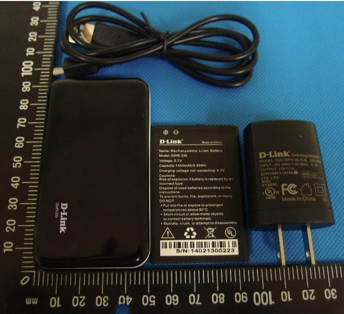
Click to zoom
Application Details
- Equipment Class
- DTS - Digital Transmission System
- Date of Grant
- May 10, 2014
- Application Purpose
- Original Equipment
- Date of Application
- May 08, 2014
- Equipment Note
- EVDO Mobile Hotspot
- Frequency Range
- 2412.00000000 - 2462.00000000
- Company
- D-Link Corporation
- Country
- United States
Documents & Files
Document Text
Text extracted from the exhibit documents filed with the FCC. Open a document above to read the original.
Users Manual
1 Portable Wi-Fi Router DWR-330 User Manual By Jack 2 Contents 1 Introduction .................................................................................................................................... 3 1.1. Features .............................................................................................................................. 3 1.2. Product Overview .............................................................................................................. 3 2. Connect to the internet .................................................................................................................. 6 2.1 Wi-Fi Router mode .............................................................................................................. 6 3. Router Web-based settings ............................................................................................................ 7 3.1 Status ................................................................................................................................... 7 3.2 Dial up ................................................................................................................................. 9 3.3 WLAN ............................................................................................................................... 10 3.4 System ............................................................................................................................... 12 4 Troubleshooting ........................................................................................................................... 14 5 FCC announcement ...................................................................................................................... 15 3 1 Introduction DWR-330 is a HSIA Wi-Fi device, working in EV-DO network. This device is a Wi-Fi router. It can provide up to 8 connections to various Wi-Fi devices such as smart phones, laptops, or tablet PCs. This quick guide provides instructions on how to use and get started with the product. For information about connection of services, please consult your service provider. 1.1. Features Built-in HSIA modem module Downlink throughput up to 3.1Mbps Uplink throughput up to 1.8Mbps WWAN connection CDMA2000 EVDO Rev. A Compatible to CDMA 2000 EVDO Rev 0 and CDMA 2000 1x RTT, IS-95 A/B. Wi-Fi 802.11 b/g/n Built-in firewall to protect your Internet Share internet connection with 8 Wi-Fi devices Micro USB interface Multi-color LED indicating status of network connection Support Microsoft Windows XP / Vista / Windows 7/Windows 8 Support Linux Support Mac OS 10.5/10.6/10.7/10.8/10.9 Antenna One Internal EVDO main antenna One Internal EVDO diversity antenna One Internal Wi-Fi antenna 1.2. Product Overview Appearance 4 LED indicator: indicator Color SolidBlinkingComment Wi‐Fi Green Router mode Transmitting ‐‐ Battery Red 0%~30% capacity without charger Less than 30% capacity when charging ‐‐ Battery Green 60% to 30% capacity without charger 60%~30% capacity when charging ‐‐ Battery Blue 99%~60% capacity without charger ; 100% Charging to full; 99%~60% capacity when charging ‐‐ Signal off ‐‐ ‐‐ standby Signal Red No Service (Error) ‐‐ ‐‐ Signal Green CDMA1X DATA Transmitting(quick) Connected without DATA(slow) ‐‐ Signal Blue EVDO DATA Transmitting(quick) Connected without DATA(slow) ‐‐ Button: Power button Rese 5 Power button: Press 3 seconds to turn on or turn off the device Reset: For system reset to default setting (Press 3 seconds) Micro USB port: Charging via a USB cable. Router mode Please refer to the illustration below for Wi-Fi Router mode. The HSIA Mobile Router can provide up to 8 Wi-Fi connections for various Wi-Fi devices to share the HSIA mobile broadband service. Battery charging by computer or USB adapter Method 1: Connect device to the USB adapter with USB cable and plug power adaptor into an appropriate wall outlet Method 2: Connect device with PC USB port by the USB cable. 6 2. Connect to the internet The Wi-Fi Router mode can provide 8 Wi-Fi connections to share the HSIA mobile broadband. 2.1 Wi-Fi Router mode The product is used standalone and computers are connected to with Wi-Fi link and in turn connect to Internet via HSIA network. The Battery is used in this case, and charging can be provided by one of the computer USB port or with separated charger. Step 1. Put the battery in the device. Step 2. Push the power button 3 seconds. Step 3. Join the Wi‐Fi network. Step 4. Open the web browser and enter 192.168.0.1 in the address bar. Step 5. Enter admin in user name & password Field. Step 6. Click WLAN -> WLAN Basic Settings on the left menu and select WPA2-PSK for the encryption type, and set WPA KEY in 8-63 alphanumeric characters. Step 7. Join the Wi-Fi network again with your password. ***WIFI Channel 12 & Channel 13 is not available in final product. The hardware is disabled inside. 7 3. Router Web-based settings DWR330 has built-in web page interface for users to configure router settings. Before you start using web browser to configure the Router, please make your client device is connecting to it. The default IP address is “192.168.0.1”, and you may use any web browser, such as Microsoft Internet Explorer, Firefox, Safari, Google Chrome and Opera, to perform following configurations. Please open your preferred web browser and enter the IP address 192.168.0.1 in the address bar. And press Enter. When following window appears, enter user name and password and click OK to enter the configuration page. The default user name and password are admin. 3.1 Status 1) Status After entering the correct IP address and loading to the first web-page, you will see the Status page. It is the default page for device. 8 Connect: Press "Connect" button to connect to the internet. Disconnect: Press "Disconnect" button to disconnect the internet. Note: Connect and Disconnect button will brighten cli…
Text truncated - open the document above for the full version.
External Photos
External photo: Mobile Hotspot Mobile Hotspot Mobile Hotspot Mobile Hotspot Mobile Hotspot battery battery charger charger Label of travel charger Data cable
ID Label/Location Info
Label&Location:
Internal Photos
Internal photo
RF Exposure Info
SAR Test Report Report No.: 2014SAR0019 East China Institute of Telecommunications Page Number : 2 of 128 TEL: +86 21 63843300 FAX: +86 21 63843301 Report Issued Date : March 18, 2014 Revision Version Report Number Revision Date Memo 2014SAR0019 00 2014/3/18 Initial creation of test report SAR Test Report Report No.: 2013SAR0019 East China Institute of Telecommunications Page Number : 3 of 128 TEL: +86 21 63843300 FAX: +86 21 63843301 Report Issued Date : March 18, 2014 CONTENTS 1 Test Laboratory ............................................................................................................................ 5 1.1 Testing Location .............................................................................................................................. 5 1.2 Testing Environment ....................................................................................................................... 5 1.3 Project Data ...................................................................................................................................... 5 1.4 Signature .......................................................................................................................................... 5 2 Statement of Compliance ........................................................................................................... 6 3 Client Information ........................................................................................................................ 8 3.1 Applicant Information ..................................................................................................................... 8 3.2 Manufacturer Information ............................................................................................................... 8 4 Equipment Under Test (EUT) and Ancillary Equipment (AE) ................................................. 9 4.1 About EUT ........................................................................................................................................ 9 4.2 Internal Identification of EUT used during the test .................................................................... 10 4.3 Internal Identification of AE used during the test ...................................................................... 10 5 TEST METHODOLOGY .............................................................................................................. 11 5.1 Applicable Limit Regulations ........................................................................................................ 11 5.2 Applicable Measurement Standards............................................................................................. 11 6 Specific Absorption Rate (SAR) ............................................................................................... 12 6.1 Introduction.................................................................................................................................... 12 6.2 SAR Definition ............................................................................................................................... 12 7 Tissue Simulating Liquids ............................................................................................................... 13 7.1 Targets for tissue simulating liquid ............................................................................................. 13 7.2 Dielectric Performance ................................................................................................................. 13 8 System verification.................................................................................................................... 15 8.1 System Setup ................................................................................................................................. 15 8.2 System Verification ....................................................................................................................... 16 9 Measurement Procedures ........................................................................................................ 17 9.1 Tests to be performed ................................................................................................................... 17 9.2 General Measurement Procedure ................................................................................................ 18 9.3 CDMA Measurement Procedures for SAR .................................................................................. 19 9.4 Wi-Fi Measurement Procedures for SAR .................................................................................... 20 9.5 Power Drift ..................................................................................................................................... 20 10 Conducted Output Power ....................................................................................................... 21 10.1 Manufacturing tolerance............................................................................................................. 21 SAR Test Report Report No.: 2013SAR0019 East China Institute of Telecommunications Page Number : 4 of 128 TEL: +86 21 63843300 FAX: +86 21 63843301 Report Issued Date : March 18, 2014 10.2 CDMA Measurement result ......................................................................................................... 24 10.3 Wi-Fi Measurement result ........................................................................................................... 26 11 Simultaneous TX SAR Considerations ................................................................................. 28 11.1 Introduction .................................................................................................................................. 28 11.2 Transmit Antenna Separation Distances ................................................................................... 28 11.3 Standa…
Text truncated - open the document above for the full version.
RF Exposure Info
SAR Test Report Report No.: 2013SAR0019 East China Institute of Telecommunications Page Number : 63 of 128 TEL: +86 21 63843300 FAX: +86 21 63843301 Report Issued Date : March 18, 2014 ANNEX B SYSTEM VALIDATION RESULTS 835MHz-Body Date/Time: 2/28/2014 Electronics: DAE4 Sn1244 Medium: Body 850 MHz Medium parameters used: f = 835 MHz; σ = 0.999 mho/m; εr = 55.15; ρ = 1000 kg/m3 Ambient Temperature:22.5°C Liquid Temperature:22.5°C Communication System: CW; Frequency: 835 MHz; Duty Cycle: 1:1 Probe: ES3DV3 - SN3252ConvF(6.14, 6.14, 6.14); Calibrated: 8/5/2013 System Validation/Area Scan(101x101x1):Measurement grid: dx=10mm, dy=10mm Maximum value of SAR (measured) = 2.387 mW/g System Validation/Zoom Scan(7x7x7)/Cube 0:Measurement grid: dx=5mm, dy=5mm, dz=5mm Reference Value = 56.938 V/m; Power Drift = -0.11 dB Peak SAR (extrapolated) = 4.027 mW/g SAR(1 g) = 2.53 mW/g; SAR(10 g) = 1.57 mW/g Maximum value of SAR (measured) = 3.302 mW/g SAR Test Report Report No.: 2013SAR0019 East China Institute of Telecommunications Page Number : 64 of 128 TEL: +86 21 63843300 FAX: +86 21 63843301 Report Issued Date : March 18, 2014 1900MHz-Body Date/Time: 3/5/2014 Electronics: DAE4 Sn1244 Medium: Body 1900 MHz Medium parameters used: f = 1900 MHz; σ = 1.524 mho/m; εr = 53.237; ρ = 1000 kg/m3 Ambient Temperature:22.5°C Liquid Temperature:22.5°C Communication System: CW; Frequency: 1900 MHz; Duty Cycle: 1:1 Probe: ES3DV3 - SN3252ConvF(5.03, 5.03, 5.03); Calibrated: 7/26/2013 System Validation/Area Scan(101x101x1):Measurement grid: dx=10mm, dy=10mm Maximum value of SAR (measured) = 9.638 mW/g System Validation/Zoom Scan(7x7x7)/Cube 0:Measurement grid: dx=5mm, dy=5mm, dz=5mm Reference Value = 101.286 V/m; Power Drift = 0.10 dB Peak SAR (extrapolated) = 18.873 mW/g SAR(1 g) = 10.843 mW/g; SAR(10 g) = 5.671 mW/g Maximum value of SAR (measured) = 14.687 mW/g SAR Test Report Report No.: 2013SAR0019 East China Institute of Telecommunications Page Number : 65 of 128 TEL: +86 21 63843300 FAX: +86 21 63843301 Report Issued Date : March 18, 2014 2450MHz-Body Date/Time: 3/3/2014 Electronics: DAE4 Sn1244 Medium: Body 2450 MHz Medium parameters used: f = 2450 MHz; σ = 1.918 mho/m; εr = 53.946; ρ = 1000 kg/m3 Ambien Temperature:22.5°C Liquid Temperature:22.5°C Communication System: CW; Frequency: 2450 MHz; Duty Cycle: 1:1 Probe: EX3DV4 - SN3754ConvF(6.66, 6.66, 6.66); Calibrated: 7/22/2013 System Validation/ Area Scan (101x101x1):Measurement grid: dx=10mm, dy=10mm Maximum value of SAR (measured) = 12.864 mW/g System Validation/Zoom Scan (7x7x7)/Cube 0:Measurement grid: dx=5mm, dy=5mm, dz=5mm Reference Value = 100.324 V/m; Power Drift = 0.01 dB Peak SAR (extrapolated) = 27.695 mW/g SAR(1 g) = 12.21 mW/g; SAR(10 g) = 5.63 mW/g Maximum value of SAR (measured) = 19.808 mW/g SAR Test Report Report No.: 2013SAR0019 East China Institute of Telecommunications Page Number : 66 of 128 TEL: +86 21 63843300 FAX: +86 21 63843301 Report Issued Date : March 18, 2014 ANNEX C SAR Measurement Setup C.1 Measurement Set-up The DASY5 system for performing compliance tests is illustrated above graphically. This system consists of the following items: Picture C.1 SAR Lab Test Measurement Set-up A standard high precision 6-axis robot (Stäubli TX=RX family) with controller, teach pendant and software. An arm extension for accommodating the data acquisition electronics (DAE). An isotropic field probe optimized and calibrated for the targeted measurement. A data acquisition electronics (DAE) which performs the signal amplification, signal multiplexing, AD-conversion, offset measurements, mechanical surface detection, collision detection, etc. The unit is battery powered with standard or rechargeable batteries. The signal is optically transmitted to the EOC. The Electro-optical converter (EOC) performs the conversion from optical to electrical signals for the digital communication to the DAE. To use optical surface detection, a special version of the EOC is required. The EOC signal is transmitted to the measurement server. The function of the measurement server is to perform the time critical tasks such as signal filtering, control of the robot operation and fast movement interrupts. The Light Beam used is for probe alignment. This improves the (absolute) accuracy of the probe positioning. A computer running WinXP and the DASY5 software. Remote control and teach pendant as well as additional circuitry for robot safety such as warning lamps, etc. The phantom, the device holder and other accessories according to the targeted measurement. SAR Test Report Report No.: 2013SAR0019 East China Institute of Telecommunications Page Number : 67 of 128 TEL: +86 21 63843300 FAX: +86 21 63843301 Report Issued Date : March 18, 2014 C.2 DASY5 E-field Probe System The SAR measurements were conducted with the dosimetric probe designed in the classical triangular configuration and optimized for dosimetric evaluation. The probe is constructed using the thick film technique; with printed resistive lines on ceramic substrates. The probe is equipped with an optical multifiber line ending at the front of the probe tip. It is connected to the EOC box on the robot arm and provides an automatic detection of the phantom surface. Half of the fibers are connected to a pulsed infrared transmitter, the other half to a synchronized receiver. As the probe approaches the surface, the reflection from the surface produces a coupling from the transmitting to the receiving fibers. This reflection increases first during the approach, reaches maximum and then decreases. If the probe is flatly touching the surface, the coupling is zero. The distance of the coupling maximum to the surface is independent of the surface reflectivity and largely independent of the surface to probe angle. The DASY5 software reads the reflection durning a software approach and looks for the maximum using 2 nd ord curve fitting. The approach is stopped at reaching the maximum. Probe Specifications:…
Text truncated - open the document above for the full version.
Test Report
RF Test Report Report No.: 2014WLA0019 East China Institute of Telecommunications Page Number : 2 of 59 TEL: +86 21 63843300 FAX: +86 21 63843301 Report Issued Date : May,07, 2014 CONTENTS 1. TEST LABORATORY ............................................................................................... 4 1.1. TESTING LOCATION ............................................................................................... 4 1.2. TESTING ENVIRONMENT ....................................................................................... 4 1.3. PROJECT DATA ...................................................................................................... 4 1.4. SIGNATURE ............................................................................................................. 4 2. CLIENT INFORMATION ........................................................................................... 5 2.1. APPLICANT INFORMATION ................................................................................... 5 2.2. MANUFACTURER INFORMATION ......................................................................... 5 3. EQUIPMENT UNDER TEST (EUT) AND ANCILLARY EQUIPMENT (AE) ............ 6 3.1. ABOUT EUT ............................................................................................................. 6 3.2. INTERNAL IDENTIFICATION OF EUT USED DURING THE TEST ...................... 6 3.3. INTERNAL IDENTIFICATION OF AE USED DURING THE TEST ......................... 6 4. REFERENCE DOCUMENTS ................................................................................... 7 4.1. REFERENCE DOCUMENTS FOR TESTING .......................................................... 7 5. SUMMARY OF TEST RESULTS.............................................................................. 8 5.1. NOTES ...................................................................................................................... 9 5.2. STATEMENTS .......................................................................................................... 9 6. TEST RESULT ........................................................................................................ 10 6.1. MAXIMUM OUTPUT POWER ................................................................................ 10 6.1.1. MAXIMUM PEAK OUTPUT POWER-CONDUCTED ............................................ 10 6.1.2. MAXIMUM AVERAGE OUTPUT POWER-CONDUCTED ..................................... 11 6.2. PEAK POWER SPECTRAL DENSITY .................................................................. 12 6.3. OCCUPIED 6DB BANDWIDTH ............................................................................. 17 6.4. BAND EDGES COMPLIANCE .............................................................................. 23 RF Test Report Report No.: 2014WLA0019 East China Institute of Telecommunications Page Number : 3 of 59 TEL: +86 21 63843300 FAX: +86 21 63843301 Report Issued Date : May,07, 2014 6.5. TRANSMITTER SPURIOUS EMISSION-CONDUCTED ....................................... 26 6.6. TRANSMITTER SPURIOUS EMISSION-RADIATED............................................ 37 6.7. AC POWERLINE CONDUCTED EMISSION ......................................................... 51 7. TEST EQUIPMENTS AND ANCILLARIES USED FOR TESTS ........................... 55 8. TEST ENVIRONMENT ........................................................................................... 57 ANNEX A DEVIATIONS FROM PRESCRIBED TEST METHODS .................................... 59 RF Test Report Report No.: 2014WLA0019 East China Institute of Telecommunications Page Number : 5 of 59 TEL: +86 21 63843300 FAX: +86 21 63843301 Report Issued Date : May,07, 2014 2. Client Information 2.1. Applicant Information Company Name: D-Link Corporation Address: No.289,Sinhu 3rd rd., Neihu District, Taipei City114, Taiwan Telephone: +886-2-66000123-5821 Postcode: 114 2.2. Manufacturer Information Company Name: D-Link Corporation Address: No.289,Sinhu 3rd rd., Neihu District, Taipei City114, Taiwan Telephone: +886-2-66000123-5821 Postcode: 114 RF Test Report Report No.: 2014WLA0019 East China Institute of Telecommunications Page Number : 6 of 59 TEL: +86 21 63843300 FAX: +86 21 63843301 Report Issued Date : May,07, 2014 3. Equipment Under Test (EUT) and Ancillary Equipment (AE) 3.1. About EUT EUT Description EVDO Mobile Hotspot Model name DWR-330 WLAN Frequency 2412MHz-2462MHz WLAN Channel Channel1-Channel11 WLAN type of modulation 802.11b:DSSS 802.11g/n: OFDM Nominal Voltage 3.7V Extreme High Voltage 4.1V Extreme Low Voltage 3.3V Note: Photographs of EUT are shown in ANNEX A of this test report. 3.2. Internal Identification of EUT used during the test EUT ID* SN or IMEI HW Version SW Version Date of receipt N04 N/A A1 v1.00 2014-02-20 *EUT ID: is used to identify the test sample in the lab internally. 3.3. Internal Identification of AE used during the test AE ID* Description SN AE1 RF cable --- AE2 --- --- *AE ID: is used to identify the test sample in the lab internally. RF Test Report Report No.: 2014WLA0019 East China Institute of Telecommunications Page Number : 7 of 59 TEL: +86 21 63843300 FAX: +86 21 63843301 Report Issued Date : May,07, 2014 4. Reference Documents 4.1. Reference Documents for testing The following documents listed in this section are referred for testing. Reference Title Version FCC Part15 FCC CFR 47, Part 15,Subpart C: 15.205 Restricted bands of operation; 15.209 Radiated emission limits, general requirements; 15.247 Operation within the bands 902-928MHz, 2400-2483.5MHz, and 5725-5850MHz. 2014 ANSI C63.10 American National Standard for Testing Unlicensed Wireless Devices 2009 RF Test Report Report No.: 2014WLA0019 East China Institute of Telecommunications Page Number : 8 of 59 TEL: +86 21 63843300 FAX: +86 21 63843301 Report Issued Date : May,07, 2014 5. Summary of Test Results A brief summary of the tests carried out is shown as following. Measurement Items Sub-clause of Part15C Sub-cl…
Text truncated - open the document above for the full version.
Test Setup Photos
Picture5:Body Phantom Mode Picture6:Body Ground Mode Picture7:Body Left Mode Picture8:Body Right Mode Picture9:Body Bottom Mode Picture10:Body Top Mode
Contact Information
Applicant
Brett Adair(General Counsel)
Technical Contact
East china institute of TelecommunicationsLiu Jianquan
[email protected]86-21-63843300
7F, G Area,No. 668, Beijing East Road, · Shanghai · China
Test Firm
East China Institute of TelecommunicationsJing Li
[email protected]862-163-8433
Technical Specifications
| # | Rule Parts | Frequency Range | Power Output |
|---|---|---|---|
| 1 | 15C | 2.41 GHz - 2.46 GHz | 91.00 mW |
Other Applications from D-Link Corporation

KA2CS6012A1
Jul 07, 20262K Fixed Indoor Cloud Camera, 2K Fixed Indoor Wi-Fi Camera
Equipment Class
DTS - Digital Transmission SystemKA2AE65UA1
Mar 02, 2026Wi-Fi 7 BE6500 USB 3.0 Dongle
Equipment Class
NII - Unlicensed National Information Infrastructure TXKA2APE9560A1
Nov 17, 2025BE9500 Celling mount Access Point
Equipment Class
6ID - 15E 6 GHz Low Power Indoor Access PointKA2AX9UA1
Dec 04, 2024AX900 Wi-Fi 6 USB Adapter, Wi-Fi 6 AX900 USB 2.0 Dongle
Equipment Class
DSS - Part 15 Spread Spectrum TransmitterKA2AC13UA1
Dec 04, 2024AC1300 Wi-Fi 5 USB Adapter, Wi-Fi 5 AC1300 USB 2.0 Dongle
Equipment Class
DTS - Digital Transmission System