KA2WR512A1HSPA 3G SOHO Router
D-Link Corporation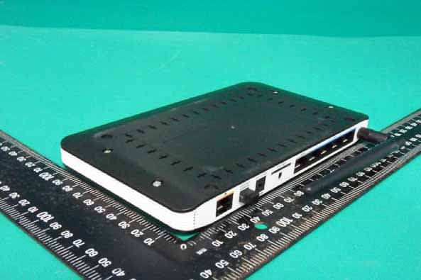
Click to zoom
Application Details
- Equipment Class
- DTS - Digital Transmission System
- Date of Grant
- Oct 06, 2011
- Application Purpose
- Original Equipment
- Date of Application
- Oct 06, 2011
- Equipment Note
- HSPA 3G SOHO Router
- Frequency Range
- 2422.00000000 - 2452.00000000
- Company
- D-Link Corporation
- Country
- United States
Documents & Files
Document Text
Text extracted from the exhibit documents filed with the FCC. Open a document above to read the original.
Users Manual
iD-Link DWR-512 User Manual D-Link reserves the right to revise this publication and to make changes in the content hereof without obligation to notify any person or organization of such revisions or changes. Trademarks D-Link and the D-Link logo are trademarks or registered trademarks of D-Link Corporation or its subsidiaries in the United States or other countries. All other company or product names mentioned herein are trademarks or registered trademarks of their respective companies. Copyright © 2011 by D-Link Corporation, Inc. All rights reserved. This publication may not be reproduced, in whole or in part, without prior expressed written permission from D-Link Corporation, Inc. Preface iiD-Link DWR-512 User Manual FCC Regulations This device complies with part 15 of the FCC Rules. Operation is subject to the following two conditions: (1) This device may not cause harmful interference, and (2) this device must accept any interference received, including interference that may cause undesired operation. This device has been tested and found to comply with the limits for a Class B digital device, pursuant to Part 15 of the FCC Rules. These limits are designed to provide reasonable protection against harmful interference in a residential installation. This equipment generates, uses and can radiated radio frequency energy and, if not installed and used in accordance with the instructions, may cause harmful interference to radio communications. However, there is no guarantee that interference will not occur in a particular installation If this equipment does cause harmful interference to radio or television reception, which can be determined by turning the equipment off and on, the user is encouraged to try to correct the interference by one or more of the following measures: • Reorient or relocate the receiving antenna. • Increase the separation between the equipment and receiver. • Connect the equipment into an outlet on a circuit different from that to which the receiver is connected. • Consult the dealer or an experienced radio/TV technician for help. Changes or modifications not expressly approved by the party responsible for compliance could void the user‘s authority to operate the equipment. The antenna(s) used for this transmitter must not be co-located or operating in conjunction with any other antenna or transmitter. This device complies with FCC radiation exposure limits set forth for an uncontrolled environment. In order to avoid the possibility of exceeding the FCC radio frequency exposure limits, human proximity to the antenna shall not be less than 20cm (8 inches) during normal operation. iiiD-Link DWR-512 User Manual Table of Contents Preface...........................................................................i Trademarks ..............................................................i FCC Regulations .....................................................ii Product Overview ........................................................1 Package Contents ...................................................1 System Requirements .............................................1 Introduction ..............................................................2 Hardware Overview .................................................3 Rear Panel .........................................................3 Front Panel ........................................................4 LEDs ..................................................................5 Installation ....................................................................6 Connect to Your Network ........................................6 Connect a Telephone ..............................................7 Wireless Installation Considerations ........................8 Configuration ...............................................................9 Web-based Configuration Utility ..............................9 Setup .....................................................................10 Internet .............................................................10 Internet Connection Setup Wizard ...............10 Manual Internet Connection Setup ...............13 Internet Connection ......................................13 Static IP ........................................................14 Dynamic IP (DHCP) .....................................15 PPPoE ..........................................................16 PPTP ............................................................17 L2TP .............................................................18 3G ................................................................19 Wireless Settings .............................................21 Wireless Connection Setup Wizard ..............21 Manual Wireless Connection Setup .............23 Wireless Settings .........................................24 Wireless Security Mode ...............................25 Wi-Fi Protected Setup ......................................28 Network Settings ..............................................30 Router Settings ............................................30 DHCP Server Settings .................................31 Message Service .............................................32 SMS Inbox ....................................................32 Create Message ...........................................33 Advanced ...............................................................34 Virtual Server ...................................................34 Application Rules .............................................36 QoS Engine .....................................................37 MAC Address Filter ..........................................38 URL Filter .........................................................39 Outbound Filter ................................................40 Inbound Filter ...................................................41 SNMP ..............................................................42 Routing .............…
Text truncated - open the document above for the full version.
Users Manual
45D-Link DWR-512 User Manual Section 3 - Configuration Tick this checkbox to use the Universal Plug and Play (UPnP™) feature. UPNP provides compatibility with various networking equipment, software, and peripherals. Select the box to allow the WAN port to be “pinged.” Blocking WAN pings may provide some extra security from hackers. Advanced Network Advanced Network contains settings which can change the way the router handles certain types of traffic. We recommend that you do not change any of these settings unless you are already familiar with them or have been instructed to make the change by one of our support personnel. After modifying any settings, click Save Settings to save your changes. Enable UPnP: Enable WAN Ping Respond: 46D-Link DWR-512 User Manual Section 3 - Configuration ADMINISTRATOR Enter and confirm the password that the admin account will use to access the router’s management interface. REMOTE MANAGEMENT Tick this check box to enable remote management. Remote management allows the DWR-512 to be configured over the Internet through a web browser. A username and password will still be required to access the Web-Management interface. Enter the Internet IP address of the PC that has access to the Broadband Router. If you enter an asterisk (*) in this field, then anyone will be able to access the Router. Adding an asterisk (*) into this field could present a security risk and is not recommended. This is the port number used to access the router. 8080 is the port usually used for the Web-Management interface. Admin The Admin page allows you to change the Administrator password and enable Remote Management. The admin has read/write access while users only have read-only access. Only the admin has the ability to change both admin and user account passwords. After modifying any settings, click Save Settings to save your changes. Admin Password: Remote Management: IP Allowed to Access: Port: Tools The TOOLS pages allow you to adjust various system setting for your router, such as the system time, firmware, and custom schedules. To view the Tools pages, click on TOOLS at the top of the screen. 47D-Link DWR-512 User Manual Section 3 - Configuration Time TIME AND DATE CONFIGURATION Select the appropriate Time Zone from the drop-down box. Tick this checkbox to allow for daylight saving adjustments. Use the dropdown boxes to specify a start date and end date for daylight saving time adjustments. AUTOMATIC TIME AND DATE CONFIGURATION Tick the Automatically synchronize with Internet time server checkbox to allow the router to use an NTP server to update the router’s internal clock. Enter an NTP server to use for time synchronization, or use the dropdown box to select one. Click the Update Now button to synchronize the time with the NTP server. This section will help you set the time zone that you are in and an NTP (Network Time Protocol) server to use. Daylight Saving can also be configured to adjust the time when needed. After modifying any settings, click Save Settings to save your changes. Time Zone: Enable Daylight Saving: NTP Server Used: 48D-Link DWR-512 User Manual Section 3 - Configuration Syslog Tick this checkbox to send the router logs to a syslog server. Enter the IP address of the syslog server that the router will send the logs to. The DWR-512 keeps a running log of events and activities occurring on the router. You may send these logs to a syslog server on your network. After modifying any settings, click Save Settings to save your changes. Enable Logging to Syslog Server: Syslog Server IP Address: 49D-Link DWR-512 User Manual Section 3 - Configuration E-mail Settings When this option is enabled, router activity logs will be e-mailed to the specified e-mail address. Enter the SMTP server IP address the router will use to send e-mails. Enter the complete IP address followed by a colon(:) and the port number. (e.g. 123.123.123.1:25). Enter the username for the SMTP account. Enter the password for the SMTP account. Enter the e-mail address where you would like the router to send e-mails to. Enter a subject for the e-mail. Click this button to send the current logs to the specified e-mail address. Enable E-mail Notification: SMTP Sever IP and Port: SMTP Username: SMTP Password: Send E-mail Alert to: E-mail Subject: E-mail Log Now: E-mail Settings allow you to send the system log files, router alert messages, and firmware update notifications to an e-mail address. After modifying any settings, click Save Settings to save your changes. 50D-Link DWR-512 User Manual Section 3 - Configuration System Use this option to save your current router configuration settings to a file. Click Save to open a file dialog, and then select a location and file name for the settings. Use this option to load previously saved router configuration settings. Click Browse... and select the saved file and then click the Upload Settings button to upload the settings to the router. This option will restore all settings back to their defaults. Any settings that have not been backed up will be lost, including any rules that you have created. Save Settings To Local Hard Drive Load Settings From Local Hard Drive: Restore To Factory Default Settings: Here, you can save the current system settings to a local hard drive. After modifying any settings, click Save Settings to save your changes. 51D-Link DWR-512 User Manual Section 3 - Configuration Firmware Displays your current firmware’s version. Displays your current firmware’s release date. After you have downloaded a new firmware, click Browse to locate the firmware on your computer, then click Upload to start the firmware upgrade. Warning: You must use a wired computer to upload the firmware file; do not use a wireless computer. During the upgrade process, do not power off your computer or router, and do not refresh the browser window until the upgrade is complete. If the firmware you want to install is not an official D-Link release, you will need to check …
Text truncated - open the document above for the full version.
External Photos
Compliance Certification Services Inc. Report No.:T110715401 Date of Issue: July 27, 2011 Page A1 / 9 PHOTOGRAPHS OF EUT External Photo (Model: DWR-512) Compliance Certification Services Inc. Report No.:T110715401 Date of Issue: July 27, 2011 Page A2 / 9 Compliance Certification Services Inc. Report No.:T110715401 Date of Issue: July 27, 2011 Page A3 / 9 Compliance Certification Services Inc. Report No.:T110715401 Date of Issue: July 27, 2011 Page A4 / 9 Antenna Gain: 3.1 dBi Antenna Gain: 3.39 dBi
ID Label/Location Info
Diagram Label location
Internal Photos
Compliance Certification Services Inc. Report No.:T110715401 Date of Issue: July 27, 2011 Page A5 / 9 Internal Photo (Model: DWR-512) Compliance Certification Services Inc. Report No.:T110715401 Date of Issue: July 27, 2011 Page A6 / 9 Compliance Certification Services Inc. Report No.:T110715401 Date of Issue: July 27, 2011 Page A7 / 9 Compliance Certification Services Inc. Report No.:T110715401 Date of Issue: July 27, 2011 Page A8 / 9 Compliance Certification Services Inc. Report No.:T110715401 Date of Issue: July 27, 2011 Page A9 / 9
Operational Description
Description of Operation The EUT is a HSPA 3G SOHO Router with IEEE 802.11b/g/n . And this device provided of transmitting speed: IEEE 802.11b:11, 5.5, 2, 1 Mbps IEEE 802.11g:54, 48 ,36, 24, 18, 12, 9, 6 Mbps IEEE 802.11n HT20 : 65, 58.5, 52, 39, 26, 19.5, 13, 6.5 Mbps IEEE 802.11n HT40 : 150 ,135, 121.5, 108, 81, 54, 40.5, 27, 13.5 Mbps the device of RF carrier is CCK, DQPSK, DBPSK, 64QAM, 16QAM, QPSK and BPSK . The device adapts DSSS and OFDM modulation. And the antenna was a Dipole antenna and provided diversity function to improve the receiving function. It allows your computer to connect to a wireless network and to share resources, such as files or printers without being bound to the network wires. And this EUT Operation in 2.4GHz Direct Sequence Spread Spectrum (D.S.S.S) and Orthogonal Frequency division Multiplex (O.F.D.M) radio transmission. In addition, its standard compliance ensures that it can communicate with any 802.11b/g/n network. Frequency Range IEEE 802.11b/g, 802.11n HT20 (DTS Band):2412MHz~2462MHz IEEE 802.11n HT40 (DTS Band):2422MHz~2452MHz Channel Spacing IEEE 802.11b/g, 802.11n HT20/HT40: 5MHz Channel Number IEEE 802.11b/g, 802.11n HT20:11 Channels IEEE 802.11n HT40 :7 Channels
Parts List/Tune Up Info
WIESON TECHNOLOGIES CO.,LTD BILL OF MATERIAL APPROVED BY:Andy CHECKD BY: Tammy DESIGNED BY: River Cust. 永洋 TITLE 3.5G SMA ANTENNA Cust.P/N 11320Y11070A1 WIESON P/N GY115HT467-003 NO. DESCRIPTION SUPPLIER SUPPLIER PART NO . UL NO. AVL QUANTITY REMARK 1 SMA MALE,SHELL:BLACK POM 1PCS 2 BASE-2,PBT:BLACK 1PCS 3 FIXED PIN,POM:BLACK 2PCS 4 BASE-1,PC;BLACK(DS-418) 1PCS 5 COVER,TPEE;BLACK(DS- 417) 1PCS 6 Mini Coaxial Cable,OD:1.37mm , FEP Black Jacket mm 7 Copper Tube,Tinned Plated 2PCS 8 Teflon,Holder 1PCS WIESON TECHNOLOGIES CO., LTD. MEASUREMENT AND PERFORMANCE PAGE : 1/8 I. SUMMARY: This report to account for the measurement setup and result of the Antenna. 1. The measurement setup includes s-parameter, pattern, and gain measurement. 2. The measured data for Antenna are presented and analysis. II. S-PARAMETER MEASUREMENT: A. Reflection coefficient : (a) Instrument:Network Analyzer. (b) Setup: (1) Calibrate the Network Analyzer by one port calibration using O.S.L. calibration kits. (2) Connect the antenna under test to the Network Analyzer. (3) Measure the S11(reflection coefficient) shown in Fig. 1. (4) Generally, the S11 is less than –10dB to ensure the 90% power into antenna and only less than 10% power back to system. Fig.1 Antenna measured in Network Analyzer WIESON TECHNOLOGIES CO., LTD. MEASUREMENT AND PERFORMANCE PAGE : 2/8 III. S-PARAMETER TEST RESULT: Frequency Sample 824MHz 960MHz 1710MHz 2170MHz 1 1.3100 2.8296 1.2017 2.1296 WIESON TECHNOLOGIES CO., LTD. MEASUREMENT AND PERFORMANCE PAGE : 3/8 IV. THE TEST INFORMATION IN ANECHOIC CHAMBER A. Scope This statement of work defines the requirements of a far-field antenna measurement range, which includes (1) One 325 cm (W) x 285 cm (H) x 640 cm (L) Antenna Measurement Anechoic Chamber, detailed requirements refer section 2.0 . (2) One Far-field Antenna Measurement System with spinning linear CP measurement capabilities, detailed requirement refer section 3.0 . (3) One broad-band transmitted antenna, detailed requirements refer section 8.0 . (4) Three NRL-4433 standard gain antennas, detailed requirements refer section 9.0 . B. Antenna Measurement Anechoic Chamber Fully anechoic chamber with dimension 325 cm in width, 285 cm in height and 640 cm in length. The quiet zone of this Chamber shall be greater than WIESON TECHNOLOGIES CO., LTD. MEASUREMENT AND PERFORMANCE PAGE : 4/8 70 cm @ 0.9 GHz, 50 cm @1.8 GHz, 44 cm @2.4 GHz, 28 cm @5.8 GHz, 16 cm @18 GHz. Contractor should be aware of this anechoic chamber is going to be used for performing far-filed antenna measurement. C. Electrical specifications Frequency Range: 800 MHz to 18 GHz, Quiet zone size: >70 cm @ 0.9 GHz, >50 cm @1.8 GHz, >44 cm @2.4 GHz, >28 cm @5.8 GHz, >16 cm @18 GHz. Quiet zone ripple: < +/- 0.5 dB @1.5~2.4 GHz, < +/- 0.25 dB @2.4~18GHz WIESON TECHNOLOGIES CO., LTD. MEASUREMENT AND PERFORMANCE PAGE : 5/8 D. Absorbers We shall design and install proper absorbers on the inner walls of the chamber to guarantee the electrical specifications . However, the absorbers height shall be no less than 24" which enables the space in the chamber to be around 203 cm (W) x 163 cm (H) x 533 cm (L). All the absorber used shall meet NRL-8093 fire retardant regulations E. Far-field Antenna Measurement System We shall supply all the hardware and software which are capable of characterizing antenna radiation patterns from 30 KHz to 6 GHz or 18GHz using the existed Agilent 5230A PNA-L or Agilent 8753ES Vector Network Analyzer. The system shall be able to automatically measure and plot single axis amplitude and phase antenna patterns in either Cartesian or polar formats. F. Far-field measurement software The software consists of the control or data acquisition software and the data plotting software. (1) The data acquisition software shall at least be capable of the following functions: *measuring single frequency per cut - single axis (azimuth); system can automatically switch frequency at the end of a scan. *measuring data in Uni-direction or bi-direction *measuring data at least with azimuth 360 degrees. (+/- 180 degrees or 0-360 degrees) *real time plot in Cartesian or polar format *screen shows real time angle position *system automatically calculates S/N ratio level based on measured WIESON TECHNOLOGIES CO., LTD. MEASUREMENT AND PERFORMANCE PAGE : 6/8 signal fluctuation *function to set positioner zero position *operator can set data taking velocity and data sampling interval *entry to allow positioner offset to any angle (2) The data plotting software shall at least be capable of the following functions: *Editing plot data *plotting data in Carttesian, Polar or delimited ASCII output with header information *plotting data in linear or dB scales *normalizing data to peak (dB), standard gain reference (dBi), or no normalization *overlaying data, (drag and dorp capability is preferable) *outputting data to any Windows supported printers G. Broadband Transmitted antenna We shall provide a linear-polarized broadband antenna with the specifications better than those listed hereafter in this article, Frequency: 1-18 GHz, Gain: >12 dBi @10 GHz, VSWR:<2,0:1, Front to Back Ration > 20 dB H. NRL4433 Standard Gain Horns We shall provide one WR-430, WR-187 one DRH0118 standard gain horns which meets the specifications of NRL-4433 report. The operating frequency of WR-430 standard gain horn is from 1.7 to 2.6 GHz, and WR-187 from 3.95 to 5.85 GHz, and DRH-0118 from 0.8 to 18GHz. We shall also provide NRL-4433 theoretical gain curves and tables for the standard gain horns. WIESON TECHNOLOGIES CO., LTD. MEASUREMENT AND PERFORMANCE PAGE : 7/8 V. CHAMBER TEST RESULT Frequency(MHz) 824 836 849 869 880 894 Gain Power -2.1 -1.82 -2.18 -1.42 -1.3 -1.23 Avg Gain -5.13 -4.38 -5.26 -5.16 -4.52 -4.32 EFFICIENCY(%) 26 25 28 30 33 35 Frequency(MHz) 900 915 925 940 960 Gain Power -0.86 -0.36 -0.18 0.19 0.21 Avg Gain -3. 52 -3.32 -3.28 -3.1 -2.66 EFFICIENCY(%) 43 45 51 48 56 Frequency(MHz) 1710 1750 1785 1805 1840 185…
Text truncated - open the document above for the full version.
Parts List/Tune Up Info
Page 1 of 18 WIESON TECHNOLOGIES CO., LTD. WIESON 3D CHAMBER TEST REPORT Customer: AMIT Project Name: CTG531AM-U11 CTG531DL-U31 WIESON P/N: GY196HT467-017 Antenna Type: WiFi Antenna(PCB) Contact Information: Tel:02-2647-1896 Sales: Teri [email protected] Ext.6315 PM: Arsenal huang [email protected] Ext.6377 Engineer: Alarn [email protected] Ext.6660 Page 2 of 18 WIESON TECHNOLOGIES CO., LTD. INDEX. I. Summary.........................................................................................................................................3 II. S-Parameter Measurement............................................................................................................3 III. S-Parameter Test Result...............................................................................................................4 IV. The Test Information Anechoic Chamber ........................................................................................6 V. Chamber Test Photo.........................................................................................................................10 VI. Chamber Test Result ...................................................................................................................... 11 VII. Product Photo ...............................................................................................................................12 Revision History Revision Date Engineer Description A 2011/05/27 Alarn NEW RELEASE No part of the information shown of this document may be used in any way without office stamp or written consent of WIESON TECHNOLOGIES CO., LTD. Page 3 of 18 WIESON TECHNOLOGIES CO., LTD. I. Summary This report to account for the measurement setup and result of the Antenna. The measurement setup includes s-parameter, pattern, and gain measurement. The measured data for Antenna are presented and analysis. II. S-Parameter Measurement A. Reflection coefficient : (a) InstrumentNetwork Analyzer. (b) Setup (1) Calibrate the Network Analyzer by one port calibration using O.S.L. calibration kits. (2) Connect the antenna under test to the Network Analyzer. (3) Measure the S11(reflection coefficient) shown in Fig. 1. (4) Generally, the S11 is less than –10dB to ensure the 90% power into antenna and only less than 10% power back to system. Fig.1 Antenna measured in Network Analyzer Page 4 of 18 WIESON TECHNOLOGIES CO., LTD. III. S-Parameter Test Result WiFi Antenna VSWR (CTG531AM-U11) Frequency Sample 2400 MHz 2450 MHz 2500 MHz 1 1.6982 1.6201 1.6298 Page 5 of 18 WIESON TECHNOLOGIES CO., LTD. WiFi Antenna VSWR(CTG531DL-U31) Frequency Sample 2400 MHz 2450 MHz 2500 MHz 1 1.5239 1.5288 1.6444 Page 6 of 18 WIESON TECHNOLOGIES CO., LTD. IV. The Test Information Anechoic Chamber A. Scope This statement of work defines the requirements of a far-field antenna measurement range, which includes (1) One 325 cm (W) x 285 cm (H) x 640 cm (L) Antenna Measurement Anechoic Chamber, detailed requirements refer section 2.0 . (2) One Far-field Antenna Measurement System with spinning linear CP measurement capabilities, detailed requirement refer section 3.0 . (3) One broad-band transmitted antenna, detailed requirements refer section 8.0 . (4) Three NRL-4433 standard gain antennas, detailed requirements refer section 9.0 . B. Antenna Measurement Anechoic Chamber Fully anechoic chamber with dimension 325 cm in width, 285 cm in height and 640 cm in length. The quiet zone of this Chamber shall be greater than Page 7 of 18 WIESON TECHNOLOGIES CO., LTD. 70 cm @ 0.9 GHz, 50 cm @1.8 GHz, 44 cm @2.4 GHz, 28 cm @5.8 GHz, 16 cm @18 GHz. Contractor should be aware of this anechoic chamber is going to be used for performing far-filed antenna measurement. C. Electrical specifications Frequency Range: 800 MHz to 18 GHz, Quiet zone size: >70 cm @ 0.9 GHz, >50 cm @1.8 GHz, >44 cm @2.4 GHz, >28 cm @5.8 GHz, >16 cm @18 GHz. Quiet zone ripple: < +/- 0.5 dB @1.5~2.4 GHz, < +/- 0.25 dB @2.4~18GHz Page 8 of 18 WIESON TECHNOLOGIES CO., LTD. D. Absorbers We shall design and install proper absorbers on the inner walls of the chamber to guarantee the electrical specifications . However, the absorbers height shall be no less than 24" which enables the space in the chamber to be around 203 cm (W) x 163 cm (H) x 533 cm (L). All the absorber used shall meet NRL-8093 fire retardant regulations E. Far-field Antenna Measurement System We shall supply all the hardware and software which are capable of characterizing antenna radiation patterns from 30 KHz to 6 GHz or 18GHz using the existed Agilent 5230A PNA-L or Agilent 8753ES Vector Network Analyzer. The system shall be able to automatically measure and plot single axis amplitude and phase antenna patterns in either Cartesian or polar formats. F. Far-field measurement software The software consists of the control or data acquisition software and the data plotting software. (1) The data acquisition software shall at least be capable of the following functions: *measuring single frequency per cut - single axis (azimuth); system can automatically switch frequency at the end of a scan. *measuring data in Uni-direction or bi-direction *measuring data at least with azimuth 360 degrees. (+/- 180 degrees or 0-360 degrees) *real time plot in Cartesian or polar format *screen shows real time angle position Page 9 of 18 WIESON TECHNOLOGIES CO., LTD. *system automatically calculates S/N ratio level based on measured signal fluctuation *function to set positioner zero position *operator can set data taking velocity and data sampling interval *entry to allow positioner offset to any angle (2) The data plotting software shall at least be capable of the following functions: *Editing plot data *plotting data in Carttesian, Polar or delimited ASCII output with header information *plotting data in linear or dB scales *normalizing data to peak (dB), standard gain reference (dBi), or no normalization *overlaying data, (drag and dorp capability is preferable) *…
Text truncated - open the document above for the full version.
RF Exposure Info
Compliance Certification Services Inc. Reference No.: T110519402-RP1 FCC IDKA2WR512A1 Report No.T110715401-RP1 Page 29 / 115 8.3 MAXIMUM PERMISSIBLE EXPOSURE According to FCC 1.1310 : The criteria listed in the following table shall be used to evaluate the environment impact of human exposure to radio frequency (RF) radiation as specified in 1.1307(b)LIMITS FOR MAXIMUM PERMISSIBLE EXPOSURE (MPE) Frequency Range (MHz) Electric Field Strength (V/m) Magnetic Field Strength (A/m) Power Density (mW/cm 2 ) Average Time (A) Limits for Occupational / Control Exposures 300-1,500 -- -- F/300 6 1,500-100,000 -- -- 5 6 (B) Limits for General Population / Uncontrol Exposures 300-1,500 -- -- F/1500 6 1,500-100,000 -- -- 1 30 CALCULATIONS Given d GP E ×× = 30 & 3770 2 E S= Where E = Field strength in Volts / meter P = Power in Watts G = Numeric antenna gain d = Distance in meters S = Power density in milliwatts / square centimeter Combining equations and re-arranging the terms to express the distance as a function of the remaining variables yields: 2 3770 30 d GP S ×× = Changing to units of mW and cm, using: P (mW) = P (W) / 1000 and d (cm) = d(m) / 100 Yields () () 2 2 0796.0 100/3770 1000/30 d GP d GP S × ×= × ×× = Where d = Distance in cm P = Power in mW G = Numeric antenna gain S = Power density in mW / cm 2 Compliance Certification Services Inc. Reference No.: T110519402-RP1 FCC IDKA2WR512A1 Report No.T110715401-RP1 Page 30 / 115 LIMIT Power Density Limit, S=1.0mW/cm 2 TEST RESULTS No non-compliance noted. () () 22 0796.0 100/3770 1000/30 d GP d GP S × ×= × ×× = G=3.39dBi = 2.18273 mW IEEE 802.11b = 0.0796 * 30.1301 * 2.18272991 ÷ 400 = 0.01309 IEEE 802.11g = 0.0796 *143.5489 * 2.18272991 ÷ 400 = 0.06235 IEEE 802.11n HT20 = 0.0796 *118.5769 * 2.18272991 ÷ 400 = 0.05151 IEEE 802.11n HT40 = 0.0796 *55.2077 * 2.18272991 ÷ 400 = 0.02398 Mode Minimum separation distance (cm) Output Power (dBm) Output Power (mw) Antenna Gain (dBi) Power Density Limit (mW/cm 2 ) Power Density at 20cm (mW/cm 2 ) IEEE 802.11b 20 14.79 30.13 3.39 1.00 0.013087 IEEE 802.11g 20 21.57 143.55 3.39 1.00 0.062352 IEEE 802.11n HT2020 20.74 118.58 3.39 1.00 0.051505 IEEE 802.11n HT4020 17.42 55.21 3.39 1.00 0.023980 REMARK: For mobile or fixed location transmitters, the maximum power density is 1.0 mW/cm 2 even if the calculation indicates that the power density would be larger. Compliance Certification Services Inc. Reference No.: T110519402-RP1 FCC IDKA2WR512A1 Report No.T110715401-RP1 Page 31 / 115 Co-Location Mode 3G Module FCC ID: Q78-ZTEMF209V WWAN MPE Channel NO Channel Frequency (MHz) Output Power (mW) Antenna Gain(dBi) Antenna Gain(mW) Power Density (S) (mW/cm2) Limit of Power Density (S) (mW/cm2) 189 836.4 1510 -1.82 0.652 0.1976 0.558 512 1850.2 720 0.85 1.216 0.1743 1 WWAN 850 MHz Collocated MPE Calculations WLAN Band (WLAN Pd)/(MPE Limit) (WWAN 850MHz)/(MP E Limit) (850 MHz WWAN fraction) + (WLAN fraction) Limit Pass/Fail 2412 - 2462 0.06235 0.3541 0.41645 1 Pass WWAN 1900 MHz Collocated MPE Calculations WLAN Band (WLAN Pd)/(MPE Limit) (WWAN 1900MHz)/(M PE Limit) (1900 MHz WWAN fraction) + (WLAN fraction) Limit Pass/Fail 2412 - 2462 0.06235 0.1743 0.23665 1 Pass
Test Report
Compliance Certification Services Inc. Reference No.: T110519402-RP1 FCC IDKA2WR512A1 Report No.T110715401-RP1 Page 1 / 115 FCC 47 CFR PART 15 SUBPART C AND ANSI C63.4: 2003 TEST REPORT For HSPA 3G SOHO Router Model Number: DWR-512 Brand: D-Link Issued for D-Link Corporation No. 289, Sinhu 3rd Rd., Neihu District, Taipei City 114, Taiwan R.O.C. Issued by Compliance Certification Services Inc. Tainan Lab. No.8,Jiucengling, Xinhua Dist., Tainan City 712, Taiwan (R.O.C.) TEL: 886-6-580-2201 FAX: 886-6-580-2202 Issued Date :…
Text truncated - open the document above for the full version.
Contact Information
Applicant
Brett Adair(General Counsel)
Test Firm
Compliance Certification Services Inc.Tommy WU
Technical Specifications
| # | Rule Parts | Frequency Range | Power Output |
|---|---|---|---|
| 2 | 15C | 2.42 GHz - 2.45 GHz | 55.20 mW |
Other Applications from D-Link Corporation

KA2CS6012A1
Jul 07, 20262K Fixed Indoor Cloud Camera, 2K Fixed Indoor Wi-Fi Camera
Equipment Class
DTS - Digital Transmission SystemKA2AE65UA1
Mar 02, 2026Wi-Fi 7 BE6500 USB 3.0 Dongle
Equipment Class
NII - Unlicensed National Information Infrastructure TXKA2APE9560A1
Nov 17, 2025BE9500 Celling mount Access Point
Equipment Class
6ID - 15E 6 GHz Low Power Indoor Access PointKA2AX9UA1
Dec 04, 2024AX900 Wi-Fi 6 USB Adapter, Wi-Fi 6 AX900 USB 2.0 Dongle
Equipment Class
DSS - Part 15 Spread Spectrum TransmitterKA2AC13UA1
Dec 04, 2024AC1300 Wi-Fi 5 USB Adapter, Wi-Fi 5 AC1300 USB 2.0 Dongle
Equipment Class
DTS - Digital Transmission System