KA2WR810A1DC-HSPA+ Le Petit Router
D-Link Corporation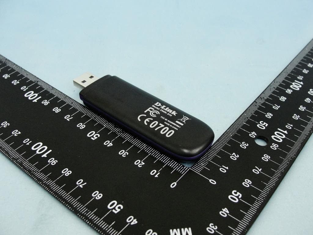
Click to zoom
Application Details
- Equipment Class
- DTS - Digital Transmission System
- Date of Grant
- Jan 21, 2014
- Application Purpose
- Original Equipment
- Date of Application
- Jan 21, 2014
- Equipment Note
- DC-HSPA+ Le Petit Router
- Frequency Range
- 2422.00000000 - 2452.00000000
- Company
- D-Link Corporation
- Country
- United States
Documents & Files
Document Text
Text extracted from the exhibit documents filed with the FCC. Open a document above to read the original.
Users Manual
User Manual For DWR-810 Introduction High-Speed Mobile Internet with 3G Connectivity The DWR-810 HSPA+ Mobile Router gives you high-speed access to the Internet wherever you are and lets you share it on the go. The built-in 3G antenna provides a reliable connection to your 3G service provider, and a separate Wi-Fi antenna gives extended coverage to the computers and mobile devices connected to the DWR-810. Mobile Internet for All of Your Devices With the DWR-810, you can get online with your notebook, smartphone, tablet, or any other wireless device using a single 3G mobile connection. The DWR-810 provides high-speed Wireless N coverage to give high-speed wireless access to everybody – whether you are with colleagues on a business trip, or travelling with friends and family. Built-in Software for Instant Access Anywhere The DWR-810 is truly plug and play, with drivers built right into the router so you can connect without the need to install anything. Open a browser, connect the router, and you can set up your network right from a web interface. This means that notebooks and netbooks without a CD‑ROM drive can connect and get up and running in no time. Once the device is set up, you can simply power it on to start up your portable mobile network, meaning that you can share your mobile Internet connection without even needing a computer. Designed for True Portability The DWR-810 HSPA+ Mobile Router is small and slim enough to carry around in your purse, bag, or pocket. It features a MicroSD card slot for optional removable storage (up to 32 GB), allowing you to always have your files and contacts on hand. Installation This section will guide you through the installation process. Connect to Your Network 1. Ensure that your DWR-810 HSPA+ Mobile Router is powered off. 2. Slide your (U)SIM card into the slot provided, ensuring that the alignment is the same as indicated by the logo next to the slot. The gold contacts on the card should be facing downwards. Caution: Always unplug and turn off the router before installing or removing the SIM card. Never insert or remove the SIM card while the router is in use. 3. After a few moments, the OLED display will show the current status of the router’s various functions. Insert a microSD Card 1. Ensure that your DWR-810 HSPA+ Mobile Router is powered off. 2. Open the cover of the microSD slot on the side of the router. 3. Insert the microSD card into the slot and push it in until it locks into place. Driver Installation When you plug the DWR-810 into your computer, any necessary drivers will immediately install (with your permission). Note: These drivers are Windows-only. Mac and Linux users will still be able to configure the DWR-810 using the web configuration utility described in Configuration Utility”. Note: For Windows systems, if there are any problems while installing the driver, please make sure you have installed Windows Media player version 11 or higher. Wireless Installation Considerations The DWR-810 can be accessed using a wireless connection from anywhere within the operating range of its wireless network. Keep in mind that the quantity, thickness, and location of walls, ceilings, or other objects that the wireless signals must pass through may adversely affect wireless signals. Ranges vary depending on the types of materials and background RF (radio frequency) noise in your home or office. The key to maximizing the wireless range is to follow these basic guidelines: 1. Minimize the number of walls and ceilings between the router and other network devices. Each wall or ceiling can reduce your adapter’s range From1 to 90 feet (1 to 30 meters). 2. Be aware of the direct line between network devices. A wall that is 1.5 feet thick (0.5 meters) appears to be almost 3 feet (1 meter) thick at a 45-degree angle. At a 2-degree angle it appears over 42 feet (14 meters) thick. Position devices so that the signal will travel straight through a wall or ceiling (instead of at an angle) for better reception. 3. Try to position access points, wireless routers, and computers so that the signal passes through open doorways and drywall. Materials such as glass, metal, brick, insulation, concrete, and water can affect wireless performance. Large objects such as fish tanks, mirrors, file cabinets, metal doors, and aluminum studs may also have a negative effect on range. 4. If you are using a 2.4 GHz cordless phone, make sure that the 2.4 GHz phone base is as far away from your wireless device as possible. The base transmits a signal even if the phone is not in use. In some cases, cordless phones, X-10 wireless devices, and electronic equipment such as ceiling fans, fluorescent lights, and home security systems may dramatically degrade wireless connectivity. Configuration Initial Connection to the Router This section will show you how to configure your new mobile router using the configuration utility that can be obtained through a software interface or a web-based user interface. When configuring the router for the first time, you will need to establish a direct connection with the router in order to access the web-based configuration utility. This can be done using the included USB, or by connecting wirelessly to the DWR-810. Once you have configured your router, you will be able to connect using the Wi-Fi settings that you have specified in the configuration process. Ensure that the router is powered on and has sufficient battery power before commencing the setup process. Connect via USB To connect to the router via USB, plug the provided micro USB cable into the micro USB port on the bottom of the router, and plug the other end into an available USB port on your computer. Your router is now ready for configuration, please refer to “Configuration Utility” on page 12 to continue the setup process. Connect via Wi-Fi Note: The following example uses Windows 7’s built-in wireless connection utility. If you are using a different operating system, or a third part…
Text truncated - open the document above for the full version.
External Photos
Photographs of EUT Report No.: EP3D1605-02 Brand Name: D-Link / Model Name: DWR-810 SPORTON INTERNATIONAL INC. Page Number : 1 of 16 TEL : 886-3-327-3456 Report Issued Date : Jan. 10, 2014 FAX : 886-3-328-4978 Report Version : Rev. 01 FCC ID: KA2WR810A1 720510 1. External Photograph of EUT Photographs of EUT Report No.: EP3D1605-02 Brand Name: D-Link / Model Name: DWR-810 SPORTON INTERNATIONAL INC. Page Number : 2 of 16 TEL : 886-3-327-3456 Report Issued Date : Jan. 10, 2014 FAX : 886-3-328-4978 Report Version : Rev. 01 FCC ID: KA2WR810A1 720510 Photographs of EUT Report No.: EP3D1605-02 Brand Name: D-Link / Model Name: DWR-810 SPORTON INTERNATIONAL INC. Page Number : 3 of 16 TEL : 886-3-327-3456 Report Issued Date : Jan. 10, 2014 FAX : 886-3-328-4978 Report Version : Rev. 01 FCC ID: KA2WR810A1 720510
Internal Photos
Photographs of EUT Report No.: EP3D1605-02 Brand Name: D-Link / Model Name: DWR-810 SPORTON INTERNATIONAL INC. Page Number : 4 of 16 TEL : 886-3-327-3456 Report Issued Date : Jan. 10, 2014 FAX : 886-3-328-4978 Report Version : Rev. 01 FCC ID: KA2WR810A1 720510 2. Internal Photograph of EUT Photographs of EUT Report No.: EP3D1605-02 Brand Name: D-Link / Model Name: DWR-810 SPORTON INTERNATIONAL INC. Page Number : 5 of 16 TEL : 886-3-327-3456 Report Issued Date : Jan. 10, 2014 FAX : 886-3-328-4978 Report Version : Rev. 01 FCC ID: KA2WR810A1 720510 Photographs of EUT Report No.: EP3D1605-02 Brand Name: D-Link / Model Name: DWR-810 SPORTON INTERNATIONAL INC. Page Number : 6 of 16 TEL : 886-3-327-3456 Report Issued Date : Jan. 10, 2014 FAX : 886-3-328-4978 Report Version : Rev. 01 FCC ID: KA2WR810A1 720510 Photographs of EUT Report No.: EP3D1605-02 Brand Name: D-Link / Model Name: DWR-810 SPORTON INTERNATIONAL INC. Page Number : 7 of 16 TEL : 886-3-327-3456 Report Issued Date : Jan. 10, 2014 FAX : 886-3-328-4978 Report Version : Rev. 01 FCC ID: KA2WR810A1 720510 Photographs of EUT Report No.: EP3D1605-02 Brand Name: D-Link / Model Name: DWR-810 SPORTON INTERNATIONAL INC. Page Number : 8 of 16 TEL : 886-3-327-3456 Report Issued Date : Jan. 10, 2014 FAX : 886-3-328-4978 Report Version : Rev. 01 FCC ID: KA2WR810A1 720510 Photographs of EUT Report No.: EP3D1605-02 Brand Name: D-Link / Model Name: DWR-810 SPORTON INTERNATIONAL INC. Page Number : 9 of 16 TEL : 886-3-327-3456 Report Issued Date : Jan. 10, 2014 FAX : 886-3-328-4978 Report Version : Rev. 01 FCC ID: KA2WR810A1 720510 Photographs of EUT Report No.: EP3D1605-02 Brand Name: D-Link / Model Name: DWR-810 SPORTON INTERNATIONAL INC. Page Number : 10 of 16 TEL : 886-3-327-3456 Report Issued Date : Jan. 10, 2014 FAX : 886-3-328-4978 Report Version : Rev. 01 FCC ID: KA2WR810A1 720510 Photographs of EUT Report No.: EP3D1605-02 Brand Name: D-Link / Model Name: DWR-810 SPORTON INTERNATIONAL INC. Page Number : 11 of 16 TEL : 886-3-327-3456 Report Issued Date : Jan. 10, 2014 FAX : 886-3-328-4978 Report Version : Rev. 01 FCC ID: KA2WR810A1 720510 Photographs of EUT Report No.: EP3D1605-02 Brand Name: D-Link / Model Name: DWR-810 SPORTON INTERNATIONAL INC. Page Number : 12 of 16 TEL : 886-3-327-3456 Report Issued Date : Jan. 10, 2014 FAX : 886-3-328-4978 Report Version : Rev. 01 FCC ID: KA2WR810A1 720510 WWAN Antenna Photographs of EUT Report No.: EP3D1605-02 Brand Name: D-Link / Model Name: DWR-810 SPORTON INTERNATIONAL INC. Page Number : 13 of 16 TEL : 886-3-327-3456 Report Issued Date : Jan. 10, 2014 FAX : 886-3-328-4978 Report Version : Rev. 01 FCC ID: KA2WR810A1 720510 Photographs of EUT Report No.: EP3D1605-02 Brand Name: D-Link / Model Name: DWR-810 SPORTON INTERNATIONAL INC. Page Number : 14 of 16 TEL : 886-3-327-3456 Report Issued Date : Jan. 10, 2014 FAX : 886-3-328-4978 Report Version : Rev. 01 FCC ID: KA2WR810A1 720510 WLAN Antenna Photographs of EUT Report No.: EP3D1605-02 Brand Name: D-Link / Model Name: DWR-810 SPORTON INTERNATIONAL INC. Page Number : 15 of 16 TEL : 886-3-327-3456 Report Issued Date : Jan. 10, 2014 FAX : 886-3-328-4978 Report Version : Rev. 01 FCC ID: KA2WR810A1 720510 Photographs of EUT Report No.: EP3D1605-02 Brand Name: D-Link / Model Name: DWR-810 SPORTON INTERNATIONAL INC. Page Number : 16 of 16 TEL : 886-3-327-3456 Report Issued Date : Jan. 10, 2014 FAX : 886-3-328-4978 Report Version : Rev. 01 FCC ID: KA2WR810A1 Diversity Antenna 720510
RF Exposure Info
SPORTON INTERNATIONAL INC. Page Number : 1 of 44 TEL : 886-3-327-3456 Report Issued Date : Jan. 14, 2014 FAX : 886-3-328-4978 Report Version : Rev. 01 FCC ID : KA2WR810A1 FCC SAR Test Report Report No. : FA3D1605-02 FCC SAR Test Report APPLICANT : D-Link Corporation EQUIPMENT : DC-HSPA+ Le Petit Router BRAND NAME : D-Link MODEL NAME : DWR-810 FCC ID : KA2WR810A1 STANDARD : FCC 47 CFR Part 2 (2.1093) ANSI/IEEE C95.1-1992 IEEE 1528-2003 The product was completely tested on Jan. 08, 2014. We, SPORTON INTERNATIONAL INC., would like to declare that the tested sample has been evaluated in accordance with the procedures and shown the compliance with the applicable technical standards. The test results in this report apply exclusively to the tested model / sample. Without written approval of SPORTON INTERNATIONAL INC., the test report shall not be reproduced except in full. SPORTON INTERNATIONAL INC. No. 52, Hwa Ya 1 st Rd., Hwa Ya Technology Park, Kwei-Shan Hsiang, Tao Yuan Hsien, Taiwan, R.O.C. Approved by: Jones Tsai / Manager Reviewed by: Eric Huang / Deputy Manager SPORTON INTERNATIONAL INC. Page Number : 2 of 44 TEL : 886-3-327-3456 Report Issued Date : Jan. 14, 2014 FAX : 886-3-328-4978 Report Version : Rev. 01 FCC ID : KA2WR810A1 FCC SAR Test Report Report No. : FA3D1605-02 Table of Contents 1. Statement of Compliance ............................................................................................................................................. 4 2. Administration Data ...................................................................................................................................................... 5 2.1 Testing Laboratory .................................................................................................................................................. 5 2.2 Applicant ................................................................................................................................................................ 5 2.3 Manufacturer .......................................................................................................................................................... 5 2.4 Application Details .................................................................................................................................................. 5 3. General Information ...................................................................................................................................................... 6 3.1 Description of Equipment Under Test (EUT) .......................................................................................................... 6 3.2 Maximum RF output power among production units .............................................................................................. 7 3.3 Applied Standard .................................................................................................................................................... 8 3.4 Device Category and SAR Limits ........................................................................................................................... 8 3.5 Test Conditions ....................................................................................................................................................... 8 4. Specific Absorption Rate (SAR) ................................................................................................................................... 9 4.1 Introduction ............................................................................................................................................................ 9 4.2 SAR Definition ........................................................................................................................................................ 9 5. SAR Measurement System ..........................................................................................................................................10 5.1 E-Field Probe ........................................................................................................................................................ 11 5.2 Data Acquisition Electronics (DAE) ....................................................................................................................... 11 5.3 Robot ....................................................................................................................................................................12 5.4 Measurement Server .............................................................................................................................................12 5.5 Phantom ................................................................................................................................................................13 5.6 Device Holder........................................................................................................................................................14 5.7 Data Storage and Evaluation ................................................................................................................................15 5.8 Test Equipment List ...............................................................................................................................................17 6. Tissue Simulating Liquids ...........................................................................................................................................18 7. System Verification Procedures .................................................................................................................................20 7.1 Purpose of System Performance check ................................................................................................................20 7.2 System Setup ........................................................................................................…
Text truncated - open the document above for the full version.
RF Exposure Info
Test Laboratory: Sporton International Inc. SAR/HAC Testing Lab Date: 2014/1/1 System Check_Body_835MHz_140101 DUT: D835V2-4d162 Communication System: CW ; Frequency: 835 MHz;Duty Cycle: 1:1 Medium: MSL_850_140101 Medium parameters used: f = 835 MHz; σ = 0.978 S/m; ε r = 53.298; ρ = 1000 kg/m 3 23.5 22.5 DASY5 Configuration: - Probe: EX3DV4 - SN3931; ConvF(9.66, 9.66, 9.66); Calibrated: 2013/9/10; - Sensor-Surface: 2mm (Mechanical Surface Detection) - Electronics: DAE3 Sn577; Calibrated: 2013/5/8 - Phantom: ELI 4.0_Front; Type: QDOVA001BB; Serial: 1029 - Measurement SW: DASY52, Version 52.8 (7);SEMCAD X Version 14.6.10 (7164) Configuration/Pin=250mW/Area Scan (61x61x1): Interpolated grid: dx=1.500 mm, dy=1.500 mm Maximum value of SAR (interpolated) = 3.18 W/kg Configuration/Pin=250mW/Zoom Scan (5x5x7)/Cube 0: Measurement grid: dx=8mm, dy=8mm, dz=5mm Reference Value = 56.655 V/m; Power Drift = -0.02 dB Peak SAR (extrapolated) = 3.68 W/kg SAR(1 g) = 2.49 W/kg; SAR(10 g) = 1.64 W/kg Maximum value of SAR (measured) = 3.12 W/kg 0 dB = 3.12 W/kg = 4.94 dBW/kg Test Laboratory: Sporton International Inc. SAR/HAC Testing Lab Date: 2014/1/1 System Check_Body_1900MHz_140101 DUT: D1900V2-5d182 Communication System: CW ; Frequency: 1900 MHz;Duty Cycle: 1:1 Medium: MSL_1900_140101 Medium parameters used: f = 1900 MHz; σ = 1.53 S/m; ε r = 52.859; ρ = 1000 kg/m 3 23.7 22.7 DASY5 Configuration: - Probe: EX3DV4 - SN3931; ConvF(7.61, 7.61, 7.61); Calibrated: 2013/9/10; - Sensor-Surface: 2mm (Mechanical Surface Detection) - Electronics: DAE3 Sn577; Calibrated: 2013/5/8 - Phantom: ELI 4.0_Front; Type: QDOVA001BB; Serial: 1029 - Measurement SW: DASY52, Version 52.8 (7);SEMCAD X Version 14.6.10 (7164) Configuration/Pin=250mW/Area Scan (61x61x1): Interpolated grid: dx=1.500 mm, dy=1.500 mm Maximum value of SAR (interpolated) = 14.3 W/kg Configuration/Pin=250mW/Zoom Scan (5x5x7)/Cube 0: Measurement grid: dx=8mm, dy=8mm, dz=5mm Reference Value = 95.599 V/m; Power Drift = -0.00 dB Peak SAR (extrapolated) = 17.7 W/kg SAR(1 g) = 9.69 W/kg; SAR(10 g) = 5 W/kg Maximum value of SAR (measured) = 13.4 W/kg 0 dB = 13.4 W/kg = 11.27 dBW/kg Test Laboratory: Sporton International Inc. SAR/HAC Testing Lab Date: 2014/1/8 System Check_Body_2450MHz_140108 DUT: D2450V2-924 Communication System: CW; Frequency: 2450 MHz;Duty Cycle: 1:1 Medium: MSL_2450_140108 Medium parameters used: f = 2450 MHz; σ = 2.02 S/m; ε r = 53.886; ρ = 1000 kg/m 3 23.5 22.5 DASY5 Configuration: - Probe: EX3DV4 - SN3661; ConvF(7.35, 7.35, 7.35); Calibrated: 2013/1/15; - Sensor-Surface: 2mm (Mechanical Surface Detection) - Electronics: DAE4 Sn1279; Calibrated: 2013/1/28 - Phantom: ELI v5.0; Type: QDOVA002AA; Serial: TP:1227 - Measurement SW: DASY52, Version 52.8 (7); SEMCAD X Version 14.6.10 (7164) Configuration/Pin=250mW/Area Scan (61x61x1): Interpolated grid: dx=1.200 mm, dy=1.200 mm Maximum value of SAR (interpolated) = 20.6 W/kg Configuration/Pin=250mW/Zoom Scan (7x7x7)/Cube 0: Measurement grid: dx=5mm, dy=5mm, dz=5mm Reference Value = 98.793 V/m; Power Drift = 0.10 dB Peak SAR (extrapolated) = 28.0 W/kg SAR(1 g) = 13.5 W/kg; SAR(10 g) = 6.28 W/kg Maximum value of SAR (measured) = 20.6 W/kg 0 dB = 20.6 W/kg = 13.14 dBW/kg
RF Exposure Info
Test Laboratory: Sporton International Inc. SAR/HAC Testing Lab Date: 2014/1/1 #01_GSM850_GPRS (4 Tx slots)_Horizontal Up_0.5cm_Ch189 Communication System: GSM850 ; Frequency: 836.4 MHz;Duty Cycle: 1:2.08 Medium: MSL_850_140101 Medium parameters used : f = 836.4 MHz; σ = 0.98 S/m; ε r = 53.279; ρ = 1000 kg/m 3 23.5 22.5 DASY5 Configuration: - Probe: EX3DV4 - SN3931; ConvF(9.66, 9.66, 9.66); Calibrated: 2013/9/10; - Sensor-Surface: 2mm (Mechanical Surface Detection) - Electronics: DAE3 Sn577; Calibrated: 2013/5/8 - Phantom: ELI 4.0_Front; Type: QDOVA001BB; Serial: 1029 - Measurement SW: DASY52, Version 52.8 (7);SEMCAD X Version 14.6.10 (7164) Configuration/Ch189/Area Scan (41x81x1): Interpolated grid: dx=1.500 mm, dy=1.500 mm Maximum value of SAR (interpolated) = 0.510 W/kg Configuration/Ch189/Zoom Scan (5x5x7)/Cube 0: Measurement grid: dx=8mm, dy=8mm, dz=5mm Reference Value = 22.393 V/m; Power Drift = -0.03 dB Peak SAR (extrapolated) = 0.571 W/kg SAR(1 g) = 0.361 W/kg; SAR(10 g) = 0.225 W/kg Maximum value of SAR (measured) = 0.470 W/kg 0 dB = 0.470 W/kg = -3.28 dBW/kg Test Laboratory: Sporton International Inc. SAR/HAC Testing Lab Date: 2014/1/1 #02_GSM850_GPRS (4 Tx slots)_Horizontal Down_0.5cm_Ch189 Communication System: GSM850 ; Frequency: 836.4 MHz;Duty Cycle: 1:2.08 Medium: MSL_850_140101 Medium parameters used : f = 836.4 MHz; σ = 0.98 S/m; ε r = 53.279; ρ = 1000 kg/m 3 23.5 22.5 DASY5 Configuration: - Probe: EX3DV4 - SN3931; ConvF(9.66, 9.66, 9.66); Calibrated: 2013/9/10; - Sensor-Surface: 2mm (Mechanical Surface Detection) - Electronics: DAE3 Sn577; Calibrated: 2013/5/8 - Phantom: ELI 4.0_Front; Type: QDOVA001BB; Serial: 1029 - Measurement SW: DASY52, Version 52.8 (7);SEMCAD X Version 14.6.10 (7164) Configuration/Ch189/Area Scan (41x81x1): Interpolated grid: dx=1.500 mm, dy=1.500 mm Maximum value of SAR (interpolated) = 0.312 W/kg Configuration/Ch189/Zoom Scan (5x5x7)/Cube 0: Measurement grid: dx=8mm, dy=8mm, dz=5mm Reference Value = 18.198 V/m; Power Drift = -0.06 dB Peak SAR (extrapolated) = 0.361 W/kg SAR(1 g) = 0.246 W/kg; SAR(10 g) = 0.162 W/kg Maximum value of SAR (measured) = 0.306 W/kg 0 dB = 0.306 W/kg = -5.14 dBW/kg Test Laboratory: Sporton International Inc. SAR/HAC Testing Lab Date: 2014/1/1 #03_GSM850_GPRS (4 Tx slots)_Vertical Front_0.5cm_Ch189 Communication System: GSM850 ; Frequency: 836.4 MHz;Duty Cycle: 1:2.08 Medium: MSL_850_140101 Medium parameters used : f = 836.4 MHz; σ = 0.98 S/m; ε r = 53.279; ρ = 1000 kg/m 3 23.5 22.5 DASY5 Configuration: - Probe: EX3DV4 - SN3931; ConvF(9.66, 9.66, 9.66); Calibrated: 2013/9/10; - Sensor-Surface: 2mm (Mechanical Surface Detection) - Electronics: DAE3 Sn577; Calibrated: 2013/5/8 - Phantom: ELI 4.0_Front; Type: QDOVA001BB; Serial: 1029 - Measurement SW: DASY52, Version 52.8 (7);SEMCAD X Version 14.6.10 (7164) Configuration/Ch189/Area Scan (41x81x1): Interpolated grid: dx=1.500 mm, dy=1.500 mm Maximum value of SAR (interpolated) = 0.158 W/kg Configuration/Ch189/Zoom Scan (5x5x7)/Cube 0: Measurement grid: dx=8mm, dy=8mm, dz=5mm Reference Value = 12.658 V/m; Power Drift = -0.08 dB Peak SAR (extrapolated) = 0.177 W/kg SAR(1 g) = 0.118 W/kg; SAR(10 g) = 0.078 W/kg Maximum value of SAR (measured) = 0.149 W/kg 0 dB = 0.149 W/kg = -8.27 dBW/kg Test Laboratory: Sporton International Inc. SAR/HAC Testing Lab Date: 2014/1/1 #04_GSM850_GPRS (4 Tx slots)_Vertical Back_0.5cm_Ch189 Communication System: GSM850 ; Frequency: 836.4 MHz;Duty Cycle: 1:2.08 Medium: MSL_850_140101 Medium parameters used : f = 836.4 MHz; σ = 0.98 S/m; ε r = 53.279; ρ = 1000 kg/m 3 23.5 22.5 DASY5 Configuration: - Probe: EX3DV4 - SN3931; ConvF(9.66, 9.66, 9.66); Calibrated: 2013/9/10; - Sensor-Surface: 2mm (Mechanical Surface Detection) - Electronics: DAE3 Sn577; Calibrated: 2013/5/8 - Phantom: ELI 4.0_Front; Type: QDOVA001BB; Serial: 1029 - Measurement SW: DASY52, Version 52.8 (7);SEMCAD X Version 14.6.10 (7164) Configuration/Ch189/Area Scan (41x81x1): Interpolated grid: dx=1.500 mm, dy=1.500 mm Maximum value of SAR (interpolated) = 0.207 W/kg Configuration/Ch189/Zoom Scan (5x5x7)/Cube 0: Measurement grid: dx=8mm, dy=8mm, dz=5mm Reference Value = 14.712 V/m; Power Drift = -0.09 dB Peak SAR (extrapolated) = 0.245 W/kg SAR(1 g) = 0.154 W/kg; SAR(10 g) = 0.096 W/kg Maximum value of SAR (measured) = 0.196 W/kg 0 dB = 0.196 W/kg = -7.08 dBW/kg Test Laboratory: Sporton International Inc. SAR/HAC Testing Lab Date: 2014/1/1 #05_GSM850_GPRS (4 Tx slots)_Tip Mode_0.5cm_Ch189 Communication System: GSM850 ; Frequency: 836.4 MHz;Duty Cycle: 1:2.08 Medium: MSL_850_140101 Medium parameters used : f = 836.4 MHz; σ = 0.98 S/m; ε r = 53.279; ρ = 1000 kg/m 3 23.5 22.5 DASY5 Configuration: - Probe: EX3DV4 - SN3931; ConvF(9.66, 9.66, 9.66); Calibrated: 2013/9/10; - Sensor-Surface: 2mm (Mechanical Surface Detection) - Electronics: DAE3 Sn577; Calibrated: 2013/5/8 - Phantom: ELI 4.0_Front; Type: QDOVA001BB; Serial: 1029 - Measurement SW: DASY52, Version 52.8 (7);SEMCAD X Version 14.6.10 (7164) Configuration/Ch189/Area Scan (41x51x1): Interpolated grid: dx=1.500 mm, dy=1.500 mm Maximum value of SAR (interpolated) = 0.0704 W/kg Configuration/Ch189/Zoom Scan (5x5x7)/Cube 0: Measurement grid: dx=8mm, dy=8mm, dz=5mm Reference Value = 9.339 V/m; Power Drift = 0.11 dB Peak SAR (extrapolated) = 0.131 W/kg SAR(1 g) = 0.053 W/kg; SAR(10 g) = 0.024 W/kg Maximum value of SAR (measured) = 0.0883 W/kg 0 dB = 0.0883 W/kg = -10.54 dBW/kg Test Laboratory: Sporton International Inc. SAR/HAC Testing Lab Date: 2014/1/1 #11_GSM1900_GPRS (4 Tx slots)_Horizontal Up_0.5cm_Ch661 Communication System: PCS ; Frequency: 1880 MHz;Duty Cycle: 1:2.08 Medium: MSL_1900_140101 Medium parameters used: f = 1880 MHz; σ = 1.513 S/m; ε r = 52.954; ρ = 1000 kg/m 3 23.7 22.7 DASY5 Configuration: - Probe: EX3DV4 - SN3931; ConvF(7.61, 7.61, 7.61); Calibrated: 2013/9/10; - Sensor-Surface: 2mm (Mechanical Surface Detection) - Electronics: DAE3 Sn577; Calibrated: 2013/5/8 - Phantom: ELI 4.0_Front; Type: QDOVA001BB; Serial: 1029 - M…
Text truncated - open the document above for the full version.
Test Report
SPORTON INTERNATIONAL INC. Page Number : 1 of 65 TEL : 886-3-327-3456 Report Issued Date : Jan. 20, 2014 FAX : 886-3-328-4978 Report Version : Rev. 01 FCC ID : KA2WR810A1 FCC RF Test Report Report No. : FR3D1605-02 FCC RF Test Report APPLICANT : D-Link Corporation EQUIPMENT : DC-HSPA+ Le Petit Router BRAND NAME : D-Link MODEL NAME : DWR-810 STANDARD : FCC Part 15 Subpart C §15.247 FCC ID : KA2WR810A1 CLASSIFICATION : (DTS) Digital Transmission System The product was received on Dec. 16, 2013 and testing was completed on Jan. 13, 2014. We, SPORTON INTERNATIONAL INC., would like to declare that the tested sample has been evaluated in accordance with the procedures and shown to be compliant with the applicable technical standards. The test results in this report apply exclusively to the tested model / sample. Without written approval of SPORTON INTERNATIONAL INC., the test report shall not be reproduced except in full. Reviewed by: Joseph Lin / Supervisor Approved by: Jones Tsai / Manager SPORTON INTERNATIONAL INC. No. 52, Hwa Ya 1 st Rd., Hwa Ya Technology Park, Kwei-Shan Hsiang, Tao Yuan Hsien, Taiwan, R.O.C. SPORTON INTERNATIONAL INC. Page Number : 2 of 65 TEL : 886-3-327-3456 Report Issued Date : Jan. 20, 2014 FAX : 886-3-328-4978 Report Version : Rev. 01 FCC ID : KA2WR810A1 FCC RF Test Report Report No. : FR3D1605-02 TABLE OF CONTENTS REVISION HISTORY .......................................................................................................................................... 3 SUMMARY OF TEST RESULT ......................................................................................................................... 4 1 GENERAL DESCRIPTION .......................................................................................................................... 5 1.1 Applicant ............................................................................................................................................ 5 1.2 Manufacturer ...................................................................................................................................... 5 1.3 Feature of Equipment Under Test ..................................................................................................... 5 1.4 Product Specification of Equipment Under Test ................................................................................ 5 1.5 Modification of EUT ........................................................................................................................... 6 1.6 Testing Site ........................................................................................................................................ 6 1.7 Applied Standards ............................................................................................................................. 6 2 TEST CONFIGURATION OF EQUIPMENT UNDER TEST ........................................................................ 7 2.1 Carrier Frequency Channel ............................................................................................................... 7 2.2 Pre-Scanned RF Power ..................................................................................................................... 8 2.3 Test Mode .......................................................................................................................................... 9 2.4 Connection Diagram of Test System ............................................................................................... 10 2.5 Support Unit used in test configuration and system ........................................................................ 11 2.6 EUT Operation Test Setup .............................................................................................................. 11 2.7 Measurement Results Explanation Example ................................................................................... 11 3 TEST RESULT ........................................................................................................................................... 12 3.1 6dB Bandwidth Measurement ......................................................................................................... 12 3.2 Output Power Measurement ............................................................................................................ 15 3.3 Power Spectral Density Measurement .....................................................................…
Text truncated - open the document above for the full version.
Contact Information
Applicant
Brett Adair(General Counsel)
Test Firm
Sporton International Inc.Alex Chen
Technical Specifications
| # | Rule Parts | Frequency Range | Power Output |
|---|---|---|---|
| 2 | 15C | 2.42 GHz - 2.45 GHz | 224.40 mW |
Other Applications from D-Link Corporation

KA2CS6012A1
Jul 07, 20262K Fixed Indoor Cloud Camera, 2K Fixed Indoor Wi-Fi Camera
Equipment Class
DTS - Digital Transmission SystemKA2AE65UA1
Mar 02, 2026Wi-Fi 7 BE6500 USB 3.0 Dongle
Equipment Class
NII - Unlicensed National Information Infrastructure TXKA2APE9560A1
Nov 17, 2025BE9500 Celling mount Access Point
Equipment Class
6ID - 15E 6 GHz Low Power Indoor Access PointKA2AX9UA1
Dec 04, 2024AX900 Wi-Fi 6 USB Adapter, Wi-Fi 6 AX900 USB 2.0 Dongle
Equipment Class
DSS - Part 15 Spread Spectrum TransmitterKA2AC13UA1
Dec 04, 2024AC1300 Wi-Fi 5 USB Adapter, Wi-Fi 5 AC1300 USB 2.0 Dongle
Equipment Class
DTS - Digital Transmission System