KDYPGM8MPGM Expander
Paradox Security Systems Ltd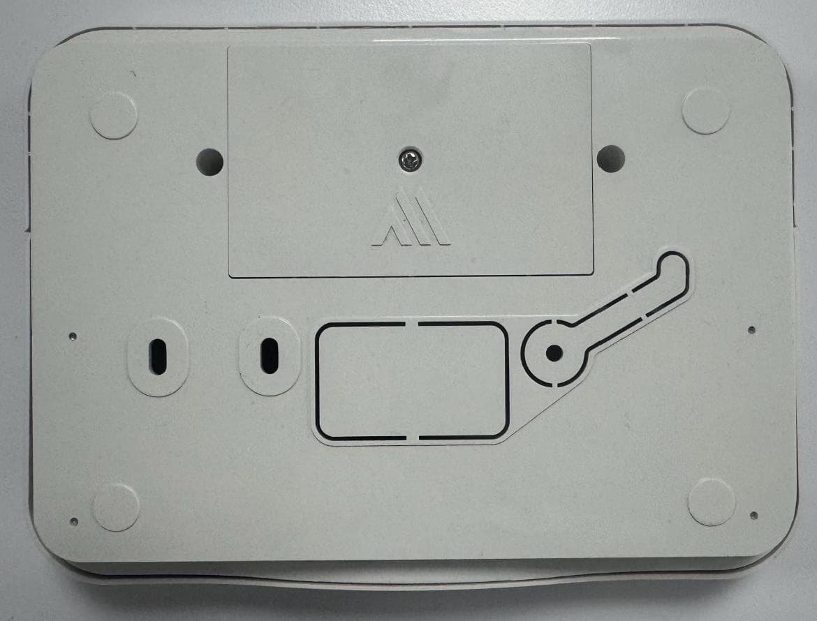
Click to zoom
Application Details
- Equipment Class
- DSS - Part 15 Spread Spectrum Transmitter
- Date of Grant
- Nov 25, 2025
- Application Purpose
- Original Equipment
- Equipment Note
- PGM Expander
- Frequency Range
- 902.25000000 - 927.55000000
- Company
- Paradox Security Systems Ltd
- Country
- Canada
Documents & Files
Document Text
Text extracted from the exhibit documents filed with the FCC. Open a document above to read the original.
Users Manual
1 FW Version: V0.68.084 Document Version: V1 Introduction The PGM8M is an 8-programmable output module designed to control external devices. It communicates with the Paradox M systems using 2-way wireless communication, featuring the latest Gaussian Frequency Shift Keying (GFSK) technology with frequency and encryption hopping. This ensures superior wireless range, enhanced encryption, supervision, and reliability. The PGM8M outputs can be controlled manually with a push switch for each output with adjustable time for manual operation via BlueEye. The PGM8M module's built-in rechargeable lithium battery allows it to operate for up to 10 days. The PGM8M features cover tamper protection. NOTE: The device is delivered with a battery charge of 10% or less. Overview Quick Installation - Experienced Installers To install PGM8M: 1. Mount the device on the wall with two screws. 2. Provide a 12 - 13.8VDC/1A power supply to power the PGM8M. Connect all required output devices. 3. Pair PGM8M with the console (Using the BlueEye application): • Go to: Hardware > Tap + on the top-right of the page >Auto learn devices. NOTE: You can instantly pair PGM8M by either pressing the Power off button momentarily, or by opening the tamper. 4. Configure PGM8M (Using the BlueEye application): • Go to: Hardware > Tap PGM8M from the device list > Enter the necessary details > Save. 2 Built-in status indications of PGM8M: Paradox Logo: • Red – Not connected to the console; offline. • White – Connected to the console; online. • Green blinking every two seconds – Battery-powered, online with console • Red blinking every two seconds – Battery-powered, offline, not communicating with the console. • Red and Green flashing (5x) – Tamper open • Green flashing (5x) – Tamper closed Output Status Indicator: • Green – Output is activated • Off – Output is deactivated Components of PGM8M The following figure displays the components of PGM8M. 3 Components of PGM8M Physical Mounting To mount PGM8M: 1. Release the screw from the bottom of the PGM8M and remove the front cover. 2. Screw the PGM8M device onto the wall through the mounting holes. 3. Provide a 12 - 13.8VDC/1A input connection to power the PGM8M. Connect all required output devices by routing cables through the wire entry holes of the device. 4. After completing the wire connection, reattach the front cover and tighten the screw at the bottom. Ensure the logo flashes green 5 times to confirm the screw is secured properly and the tamper is closed. NOTE: The internal lithium battery is not dealer-replaceable and is designed to last throughout the device's life expectancy. Pairing PGM8M with the Wireless M Console The pairing and configuration settings of PGM8M are managed through the BlueEye application. Prerequisites Ensure that: 1. The PGM8M is within the range of the console. 2. The BlueEye application is installed on your mobile and connected to the site. 3. The M console is powered on (Paradox logo color - white, red, or green). Pairing PGM8M To pair the PGM8M with the wireless console by an installer: 1. When in the Hardware tab, tap + on the top-right of the page, and then tap Auto learn wireless devices. The wireless console searches for new devices and a rotating radar icon is displayed. This may take up to 6 minutes. To pair instantly, press momentarily on the power off button, or open the tamper. The device pairs with the console and it appears at the top of the device list with a new tag and voice announcements. 4 After pairing, to identify the new device, you can trigger the PGM8M tamper. A T symbol appears on the device tab in the BlueEye application. Alternatively, you can find a device by finding the serial number in the device list, or use the Search tool at the top right of the screen in the BlueEye application. Configuring You can configure the PGM8M settings in the BlueEye application. To configure the PGM8M settings: 1. When in the Hardware tab, tap the PGM8M device. 2. On the page that opens, tap the output you want to configure and enter the necessary details. 3. Tap Save. For details about each parameter displayed on the page, see Table 1. 5 The following table lists the parameters displayed for configuring the PGM8M, along with their descriptions. Table 1 Parameter Description Label Enter a label for the device. PGM State after AC Restore Select how the PGM behaves after power restoration: • Resume Last State • On • Off PGM Number Select the PGM number. PGM Type Define the PGM type: • Regular • Restricted • Installer Verify App PGM Status with Zone Assigns zone to verify the status of the PGM. Activation Timer Sets the duration for PGM activation. Extend on Time by Zone Opening Extends the PGM activation duration when the assigned zone is triggered. 6 Keypad Activation with Code Enables PGM activation using a keypad and a code. Follow Events, Schedule Defines the PGM activation behavior: • None: No automatic activation; the PGM operates solely based on manual inputs. • Zone: Activates the PGM when a specific zone is triggered. • Area Status: Activates the PGM based on the status of a particular area. • Trouble: Activates the PGM in response to system trouble conditions. • Schedule: Activates the PGM according to a predefined schedule. • Module Temperature: Activates the PGM when the module's temperature reaches a specified threshold. PGM Communication Output Specify the notification type, method, and receivers for PGM communication. Scenarios Example automation scenarios: • Activate lobby when arming • Deactivate the lobby when disarming PGM Activation History Displays the history of PGM activations. Reset to Default This will reset the device to the factory default settings. NOTE: Only an installer can reset the device. About This tab displays details such as the installation date, production date, last programming date, battery replacements, battery history, and upgrade history. Suspend Device Disables monitoring of the device in the system. Del…
Text truncated - open the document above for the full version.
Attestation Statements
Agent letter FCC attestation statement Kiwa Page 1 of 2 RF_753, Issue 2 15-02-2023 [PLACE ON APPLICANT/COMPANY LETTERHEAD] U.S. Agent Designation for Service of Process (Applicant and U.S. Agent are Separate Parties) TO: Kiwa Nederland B.V. Wilmersdorf 50 7327 AC Apeldoorn Postbus 137 7300 AC Apeldoorn Netherlands ATTENTION: FCC Certification – Section 2.911(d)(7) Information Designated U.S. Agent Company name: Paradox USA of Florida FRN: 0034232025 Contact person name: Jordan Peles Street address: 2881 W McNab Rd ZIP/City/State Pompano Beach, FL 33069 Telephone number: 954-933-2156 Email address: [email protected] Signature: Date: This letter is to confirm that we (“the Designated U.S. Agent) have accepted the responsibility to act as the Designated U.S. Agent for Service of Process as required by section 47 CFR 2.911(d)(7) on behalf of the Applicant noted below. The Applicant acknowledges that they must maintain an agent for no less than one year after terminating all marketing and importation OR the conclusion of any Commission- related proceeding involving the equipment. The applicant further acknowledges their responsibility to inform the FCC whenever the Designated U.S. Agent information above changes. Applicant Company name: Paradox Security Systems Ltd. FCC ID: KDYPGM8M FRN: 0007597024 Contact person name: Alex Chaplik Street address: 780 Industriel Blvd ZIP/City/State Saint-Eustache, Quebec J7R 5V3 Telephone number: 450-491-7444 Email address: [email protected] Agent letter FCC attestation statement Kiwa Page 2 of 2 RF_753, Issue 2 15-02-2023 [PLACE ON APPLICANT/COMPANY LETTERHEAD] Signature: Date: 03.06.2025 Revision Record Sheet: Revision Section number Page number Date Remark(s) issued by 01 07-02-20231 st version RvdM 02 1 15-05-2023Added FRN to Agent details RvdM Issued/modified by : Richard van der Meer Function : Certification assessor Revision : 02 Date : 15-02-2023 Verified by : Willem Jan Jong Function : Team Lead Date : __-02-2023 Released by : Axel Gase Function : Manager Quality Assurance Date of release: : __-02-2023
Attestation Statements
Covered list attestation FCC application letter Kiwa RF_755_03 Page 1 of 2 06-06-2024 [PLACE COMPANY LOGO HERE OR PUT ON COMPANY LETTERHEAD] Certification Application Attestation Statements Paradox Security Systems Ltd. <FRN: 0007597024 <780 Industriel Blvd, Saint-Eustache> <J7R 5V3> < Quebec > < Canada > Subject: FCC ID: < KDYPGM8M > To Whom It May Concern: Statement for 47 CFR section 2.911(d)(5)(i) [Paradox Security Systems Ltd.] certifies that as of the date of the application the equipment for which authorization is sought is not “covered” equipment 1 prohibited from receiving an equipment authorization pursuant to section 2.903 of the FCC rules. If the equipment for which the applicant seeks authorization is produced by any of the entities identified on the current Covered List, including affiliates or subsidiaries of the named companies, the applicant must include an explanation on why the equipment is not “covered” equipment. Insert applicant company name. (“Paradox Security Systems Ltd.”) certifies that the equipment for which authorization is sought does not include cybersecurity or anti-virus software produced or provided by Kaspersky Lab, Inc. or any of its successors and assignees, including equipment with integrated Kaspersky Lab, Inc. (or any of its successors and assignees) cybersecurity or anti-virus software pursuant to DA-24-886 and KDB 986446 D01 Covered Equipment Guidance section B(2a). Additional Explanation: <N/A> Statement for 47 CFR section 2.911(d)(5)(ii) [Paradox Security Systems Ltd.] (“the applicant”) certifies that, as of the date of the filing of this application, the applicant - is / - is not (3) identified on the Covered List as an entity producing “covered” equipment. Date: May 15, 2025 City: Quebec Name (2) : Alex Chaplik Function: Certification manager Telephone number: 450-491-7444 Email address: [email protected] 1 - The Commission’s Covered List is published by the Public Safety and Homeland Security Bureau and posted on the Commission’s website. This Covered List, which is periodically updated, identifies particular equipment, produced by particular entities, that constitutes “covered” equipment. https://www.fcc.gov/supplychain/coveredlist . Covered list attestation FCC application letter Kiwa RF_755_03 Page 2 of 2 06-06-2024 (2): For FCC it must be the Grantee Code “owner” or the authorized agent. (3): double click on the appropriate box and select ‘’checked” then “OK” [PLACE COMPANY LOGO HERE OR PUT ON COMPANY LETTERHEAD] Signature: Revision Record Sheet: Revision Section number Page number Date Remark(s) issued by 01 07-02-2023 1 st version RvM 02 1 15-02-2023 Changed Applicant to Company and added “Subject: FCC ID: “ RvdM 03 1 06-06-2024 FRN added at certification application and included [Insert Company Name Here] for the statements RvdM Issued/modified by : Richard van de Meer Function : Certification assessor Revision 03 Date : 06-06-2024 Verified by : Willem Jan Jong Function : Team Lead Date : 06-06-2024 Released by : Axel Gase Function : Manager Quality Assurance Date of release: : 06-06-2024
Cover Letter(s)
RF_160_05 Declaration of Authorisation Date of issue 02-01-2023 (On manufacturer’s company letter heading) Declaration of Authorization We Name: Paradox Security Systems Ltd. Address: 780 Industriel Blvd City: Saint-Eustache, Quebec J7R 5V3 Country: Canada Declare that: Name Representative of agent: Peysahov Sheynin Svetlana (1) Agent Company name: Hermon Laboratories Ltd. Address: Harakevet Industrial Zone City: Binyamina 30500 Country Israel is authorized to apply for Certification of the following product(s): Product description: PGM Expander Type designation: PGM8M, PGM4M Trademark: Paradox Validity/ expiry date July 23, 2026 on our behalf. Date: July 23, 2025 City: Saint-Eustache Name: Alex Chaplik Function: Certification manager Signature: Notes: (1): Required for FCC application (2): For FCC it must be the Grantee Code “owner” or the authorized agent. Revision Record Sheet: Revision Section number Page number Date Remark(s) issued by 02 1 02-01-2023 History sheet added AG Issued/modified by : Axel Gase Function : Quality Manager Revision : 02 Date : 02-01-2023 Verified by : Willem Jan Jong Function : Team Lead Date : 02-01-2023 Released by : Axel Gase Function : Manager Quality Assurance Date of release: : 02-01-2023
Cover Letter(s)
FCC, Request for non-disclosure Date: 23-06-2023 RF_501, Issue 11 Page 1 of 2 Company Name: Paradox Security Systems Address: 780 Industriel Blvd City: Saint-Eustache, QC, J7R 5V3 Country: Canad To: Kiwa Netherlands B.V., Dept. FCC TCB Wilmersdorf 50 7327 AC Apeldoorn The Netherlands Subject: Request for confidentiality FCC ID: KDYPGM8M Reference number: 54975 Dear FCC TCB, 1. Long-Term Confidentiality Pursuant to 47 CFR Section 0.459(a) & (b), we hereby requests non-disclosure and confidential treatment of the following materials submitted in support of FCC certification application: Bill(s) of Material Block Diagrams Operational Description Schematic Diagrams Tune-up Procedure Above materials contain secrets, proprietary and technical information, which would customarily be guarded from competitors under 47 CFR, section 0.457(d)(2). Disclosure or publication or any portion of this company confidential material to other parties could cause substantial competitive harm and provide unjustified benefits for competitors. 2. Short-Term Confidentiality (STC) Pursuant to Public Notice DA 04-1705 of the Commission’s policy, in order to comply with the marketing regulations in 47 CFR §2.803 and the importation rules in 47 CFR §2.1204, applicant hereby requests Short-Term Confidential treatment of the following materials (See notes below): Internal Photos User’s Manual Test Set-up Photos External Photos Justification: Patent pending, Competative advantage Date: July 23, 2025 Name and signature of applicant: Alex Chaplik Notes: 1) A document or type of document can only have ONE type of confidentiality! 2) Short-Term confidentiality is in principle for 45 days from date of grant; it can be extended max 3 times (total time 180 days max.)! The planned date should state in the RF731 application form. 3) FCC must be informed when marketing begins earlier. 4) Release takes place automatically thus extension must be requested in time. Telefication does not remind you of this! FCC, Request for non-disclosure Date: 23-06-2023 RF_501, Issue 11 Page 2 of 2 5) Request for extension or for release must be received by Kiwa NL B.V. at least 7 days before date of actual marketing or before expiration of the STC period FCC, Request for non-disclosure Date: 23-06-2023 RF_501, Issue 11 Page 3 of 2 Revision Record Sheet: Revision Section number Page number Date Remark(s) issued by 10 1 02-01-2023 History sheet added AG 11 1 & 2 23-06-2023 Corrected date and page# WJJ Issued/modified by : Willem Jan Jong Function : Team Lead Revision : 11 Date : 23-06-2023 Verified by : Axel Gase Function : Manager Quality Assurance Date : 23-06-2023 Released by : Axel Gase Function : Manager Quality Assurance Date of release: : 23-06-2023
Cover Letter(s)
Page 1 of 1 July 23, 2025 Telefication B.V. Attn: Dept. FCC TCB Wilmersdorf 50 7327 AC Apeldoorn The Netherlands Subject: Application for certification of a PGM Expander, PGM8M, PGM4M, FCC ID: KDYPGM8M Dear Gentlemen, Please find attached our application for certification of the PGM Expander, brand name PGM8M, PGM4M, FCC ID: KDYPGM8M, prepared in accordance with FCC Rules parts 2 and 15, section 15.247(FHSS). The product testing and this application for certification were performed by Hermon Laboratories, which is recognized and accredited by FCC, Test Firm Registration Number is 927748, Designation Number is IL1001. Hermon Labs responsible person is Mr. Michael Nikishin, tel: +972 4626 8440, fax:+972 4628 8277, e-mail: [email protected]. Please send an invoice to Hermon Labs. We hope this application satisfies your requirements. Sincerely yours, Alex Chaplik, Certification Manager
Cover Letter(s)
Ref: PGM4M_PGM8M_Similarity_Declaration_Rev1 To: Hermon Labs Declaration of Similarity It is hereby declared that 4-programmable output module PGM4M is a variant of 8-programmable output module PGM8M and both models operate on 915 MHz band. Both PGM modules have the same Layout, Electronic Hardware, Firmware and Plastic Enclosure. The only difference between PGM4M and PGM8M is in number of outputs (output indicators, tampers and relays), some components were removed in PGM4M model because they are not required for the functionality of their specific application. PGM4M (4 PGMs assembled on board) is a subset product of PGM8M (8 PGMs assembled on board). The components that are removed from PGM8M and convert the product to PGM4M, are not changing the radio functions. External and Internal photos of each model provided. Both models have same HW and FW versions as indicated in the table low: Brand Model HW Version FW version Description Paradox PGM8M 333-6007-995 V1.00 8-programmable output module Paradox PGM4M 333-6007-995 V1.00 4-programmable output module Aug-19-2025 Alex Chaplik Certification Manager
External Photos
Paradox Security Systems Ltd. FCC ID: KDYPGM8M IC: 2438A-PGM8M Page 1 of 3 EXTERNAL PHOTOGRAPHS This document contains 2 photographs Paradox Security Systems Ltd. FCC ID: KDYPGM8M IC: 2438A-PGM8M Page 2 of 3 Photograph No.1 PGM8M Front view Photograph No.2 PGM4M Front view Photograph No.3 PGM8M Rear view Paradox Security Systems Ltd. FCC ID: KDYPGM8M IC: 2438A-PGM8M Page 3 of 3 Photograph No.4 PGM4M Rear view
RF Exposure Info
FCC ID: KDYPGM8M Page 1 of 1 Environmental evaluation and exposure limit according to FCC CFR 47part 1, §1.1307, §1.1310 The PGM Expander are classified as a mobile device. The PGM Expander includes transmitter operating according to FCC part 15 subpart C section 15.247 (FHSS) The FCC limit for power density for general population/uncontrolled exposure is f/1500 mW/cm 2 for 300 – 1500 MHz frequency range: P = 902.25/1500 = 0.6 mW/cm 2 The power density P (mW/cm 2 ) = P T / 4 r 2 P T is the transmitted power, which is equal to the peak transmitter output power 1.84 dBm plus maximum antenna gain 0 dBi, the maximum equivalent isotropically radiated power EIRP is P T = 19.67 dBm + 0 dBi = 19.67 dBm = 92.68 mW. The power density at 20 cm (minimum safe distance, required for mobile devices), calculated as follows: Compliance with FCC limit: 92.68 mW / 4 (20 cm) 2 = 0.018 mW/cm 2 << 0.6 mW/cm 2 General public cannot be exposed to dangerous RF level.
Test Report
Ref: Antenna_Manufacturer_Declaration_Rev0 To: Hermon Labs Manufacturer Declaration of Similarity We, Paradox Security Systems Ltd. located in 780 Industrial Boulevard St.Eustache, Quebec J7R 5V3, Canada declare that internal coil antenna, model KX-NZTH914 by Kexin which we use in our models, operates on 915MHz frequency band. The max (peak gain) of antenna is 2.2dBi according to the datasheet, but in our applications, we are using 0dBi gain and this parameter was considered in all calculations. Aug-19-2025 Alex Chaplik Certification Manager
Test Report
Hermon Laboratories Ltd. 66 HaTachana str., P.O. Box 23, Binyamina 3055001, Israel Tel. +972 4628 8001 Fax. +972 4628 8277 E-mail: [email protected] Page 1 of 58 Report ID: PARRAD_FCC.54975_TR.doc Date of Issue: 22-Jul-25 ELECTRICAL TESTING 0839.01 ז0BTEST REPORT 1BACCORDING TO: FCC 47CFR part 15 subpart C §15.247 (FHSS), RSS-247 Issue 3:2023, RSS-Gen Issue 5 FOR: Paradox Security Systems LTD. PGM Expander, models: PGM8M, PGM4M FCC ID: KDYPGM8M 7BIC: 2438A-PGM8M This report is in conformity with ISO/ IEC 17025. The "A2LA Accredited" symbol endorsement applies only to the tests and calibrations that are listed in the scope of Hermon Laboratories accreditation. The test results relate only to the items tested. This test report shall not be reproduced in any form except in full with the written approval of Hermon Laboratories Ltd. Report ID: PARRAD_FCC.54975_TR.doc Date of Issue: 22-Jul-25 Page 2 of 58 Table of contents 1 Applicant information ..................................................................................................................................................... 3 2 Equipment under test attributes .................................................................................................................................... 3 3 Manufacturer information .............................................................................................................................................. 3 4 Test details .................................................................................................................................................................... 3 5 Tests summary .............................................................................................................................................................. 4 6 EUT description ............................................................................................................................................................. 5 6.1 General information ....................................................................................................................................................... 5 6.2 Ports and lines .............................................................................................................................................................. 5 6.3 Test configuration .......................................................................................................................................................... 5 6.4 Transmitter characteristics ............................................................................................................................................ 6 7 Transmitter tests according to 47CFR part 15 subpart C and RSS-247 requirements .................................................. 7 7.1 20 dB bandwidth ........................................................................................................................................................... 7 7.2 Carrier frequency separation ....................................................................................................................................... 10 7.3 Number of hopping frequencies .................................................................................................................................. 12 7.4 Average time of occupancy ......................................................................................................................................... 17 7.5 Peak output power ...................................................................................................................................................... 20 7.6 Field strength of spurious emissions ........................................................................................................................... 24 7.7 Band edge radiated emissions .................................................................................................................................... 36 7.8 Conducted emissions .................................................................................................................................................. 40 7.9 Antenna requirements ................................................................................................................................................. 43 8 Unintentional emissions .............................................................................................................................................. 44 8.1 Conducted emissions .................................................................................................................................................. 44 8.2 Radiated emission measurements .............................................................................................................................. 47 9 APPENDIX A Test equipment and ancillaries used for tests ....................................................................................... 51 10 APPENDIX B Test equipment correction factors ......................................................................................................... 52 11 APPENDIX C Measurement uncertainties .................................................................................................................. 55 12 APPENDIX D Test laboratory description ................................................................................................................... 56 13 APPENDIX E Specification references ........................................................................................................................ 56 14 APPENDIX F Abbreviations and acronyms ................................................................................................................. 57 15 APPENDIX G Manufacturer’s declaration ...................................................................................................................…
Text truncated - open the document above for the full version.
Contact Information
Applicant
Alex Chaplik(Certification Manager)
[email protected]Fax: 450-491-2313
Technical Contact
Paradox Security Systems Ltd.Alex Chaplik
[email protected]Fax: 972 4850 0498
780 Industrial Blvd · Canada
Test Firm
Hermon Laboratories Ltd.George Shleimovich
[email protected]Fax: +972 4 626 8469
Technical Specifications
| # | Rule Parts | Frequency Range | Power Output |
|---|---|---|---|
| 1 | 15C | 902.25 MHz - 927.55 MHz | 93.00 mW |
Other Applications from Paradox Security Systems Ltd
KDYX45
May 07, 2026Hybrid Head Unit/Console
Equipment Class
DSS - Part 15 Spread Spectrum TransmitterKDYZP2M
Dec 23, 2025Dual Input /Output Wireless Bus Expander Two Garage Door
Equipment Class
DSS - Part 15 Spread Spectrum TransmitterKDYK70M
Dec 12, 20257 inch Touchscreen Keypad
Equipment Class
DTS - Digital Transmission SystemKDYDCT12M
Nov 25, 2025Door /Window Magnetic Contact + Zone
Equipment Class
DSS - Part 15 Spread Spectrum TransmitterKDYPMD5M
Sep 08, 2025Indoor Miniature Motion Detector
Equipment Class
DSS - Part 15 Spread Spectrum Transmitter