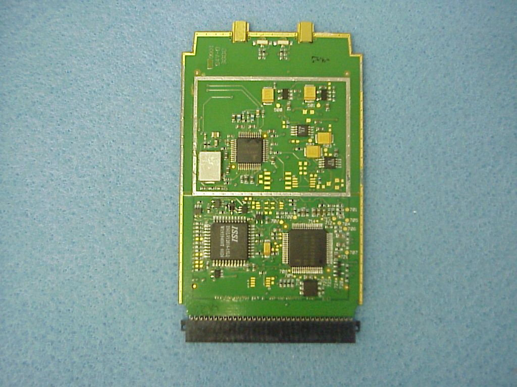
KDZLXE6526MWireless LAN Card in Class A terminals
Honeywell International, Inc.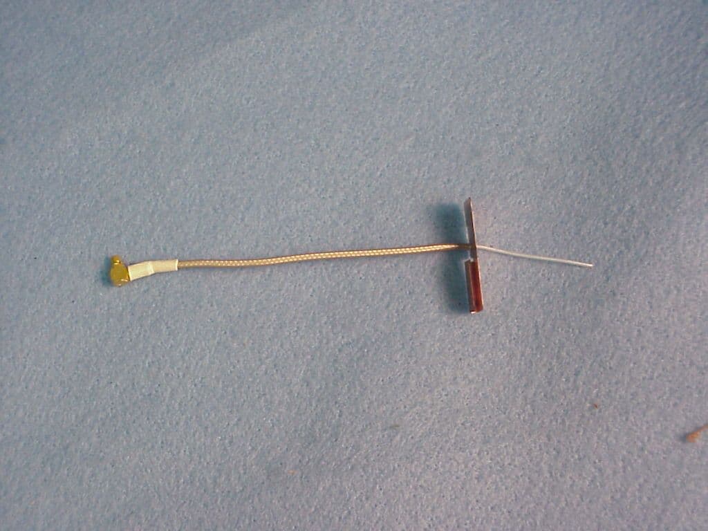
Click to zoom
Application Details
- Equipment Class
- DSS - Part 15 Spread Spectrum Transmitter
- Date of Grant
- Mar 26, 2001
- Application Purpose
- Original Equipment
- Date of Application
- Dec 20, 2000
- Equipment Note
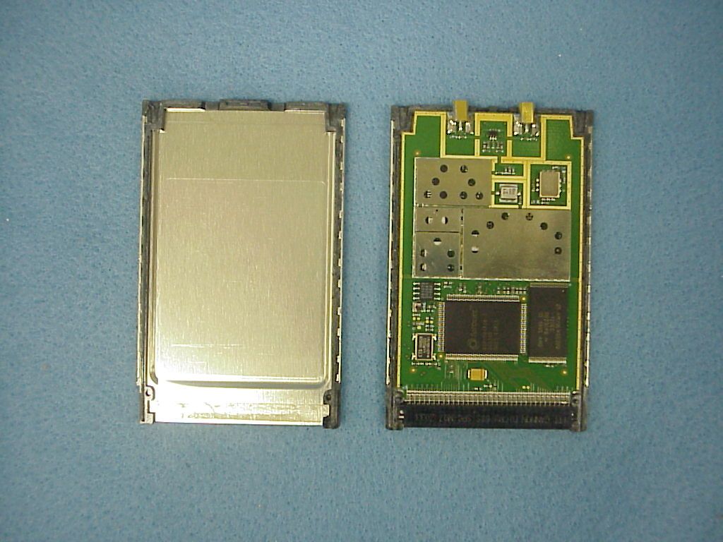
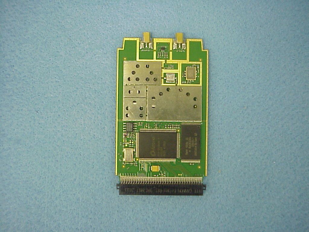
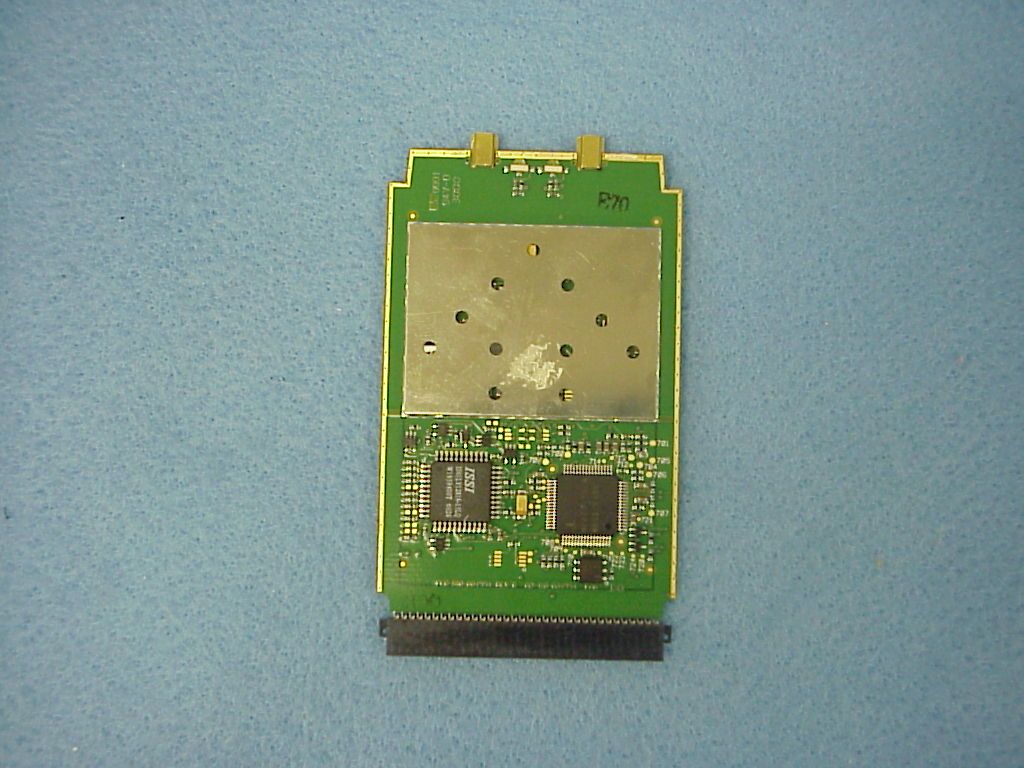
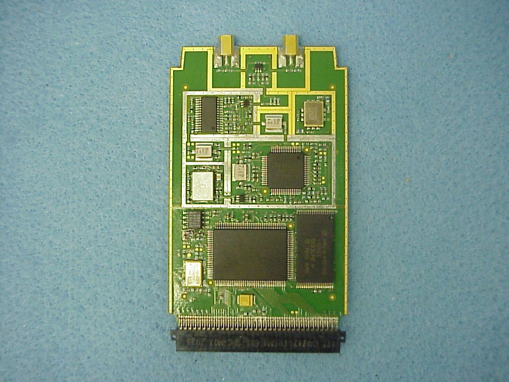
- Wireless LAN Card in Class A terminals
- Frequency Range
- 2412.00000000 - 2462.00000000
- Country
- United States
Documents & Files

Document Text
Text extracted from the exhibit documents filed with the FCC. Open a document above to read the original.
Users Manual
LANGUAGE : ENGLISH Notice: LXE Inc. reserves the right to make improvements or changes in the products described in this manual at any time without notice. While reasonable efforts have been made in the preparation of this document to assure its accuracy, LXE assumes no liability resulting from any errors or omissions in this document, or from the use of the information contained herein. Copyright Notice: This manual is copyrighted. All rights are reserved. This document may not, in whole or in part, be copied, photocopied, reproduced, translated or reduced to any electronic medium or machine-readable form without prior consent, in writing, from LXE Inc. Copyright © 2000 by LXE Inc. An EMS Technologies Company. 125 Technology Parkway, Norcross, GA 30092 U.S.A. (770) 447-4224 LXE is a registered trademark of LXE Inc. All other brand or product names are trademarks or registered trademarks of their respective companies or organizations. Notice: The long term characteristics or the possible physiological effects of radio frequency electromagnetic fields have not been investigated by UL. FCC Information: This device complies with FCC Rules, part 15. Operation is subject to the following conditions: 1.This device may not cause harmful interference and 2.This device must accept any interference that may be received, including interference that may cause undesired operation. Note: This equipment has been tested and found to comply with the limits for a Class A digital device, pursuant to part 15 of the FCC rules. These limits are designed to provide reasonable protection against harmful interference when the equipment is operated in a commercial environment. This equipment generates, uses, and can radiate radio frequency energy and, if not installed and used in accordance with the instruction manual, may cause harmful interference to radio communications. Operation of this equipment in a residential area is likely to cause harmful interference in which case the user will be required to correct the interference at his own expense. Warning: Changes or modifications to this device not expressly approved by LXE, Inc., could void the user’s authority to operate this equipment. EMC Directive Requirements: This is a Class A product. In a domestic environment this product may cause radio interference in which case the user may be required to take adequate measures. Industry Canada: This Class A digital apparatus meets all requirements of the Canadian Interference Causing Equipment Regulations. Operation is subject to the following two conditions: (1) this device may not cause harmful interference, and (2) this device must accept any interference received, including interference that may cause undesired operation. Cet appareil numérique de la classe A respecte toutes les exigences du Règlement sur le matériel brouiller du Canada. Le present appareil numérique n’emet pas de bruits radioélectriques dépassant les limites applicables aux appareils numeriques de le Classe A préscrites dans le Reglement sur le brouillage radioélectrique édits par le ministere des Communications du Canada. Li-Ion Battery When disposing of the MX3 Main Battery, the following precautions should be observed: The battery should be disposed of promptly. The battery should not be disassembled or crushed. The battery should not be heated above 212°F (100°C)or incinerated.
Cover Letter(s)
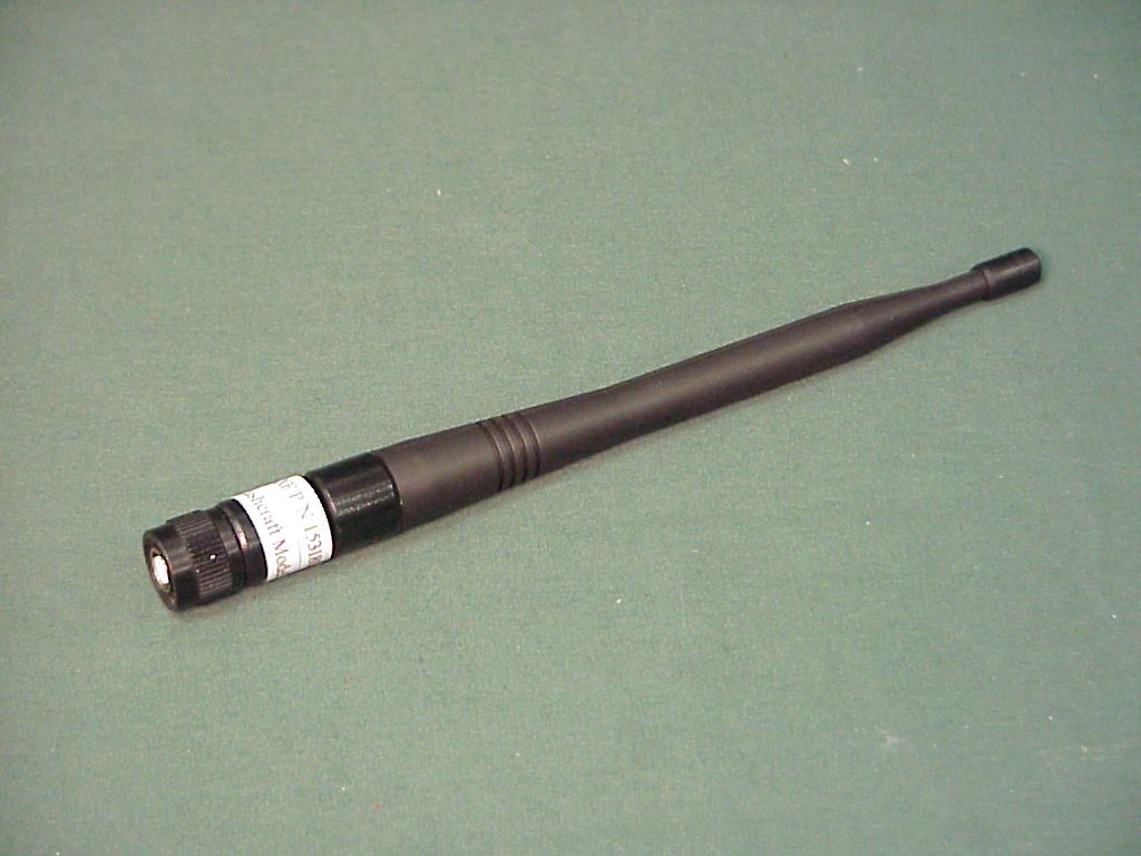
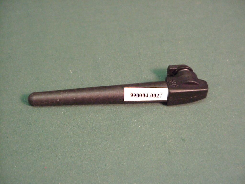
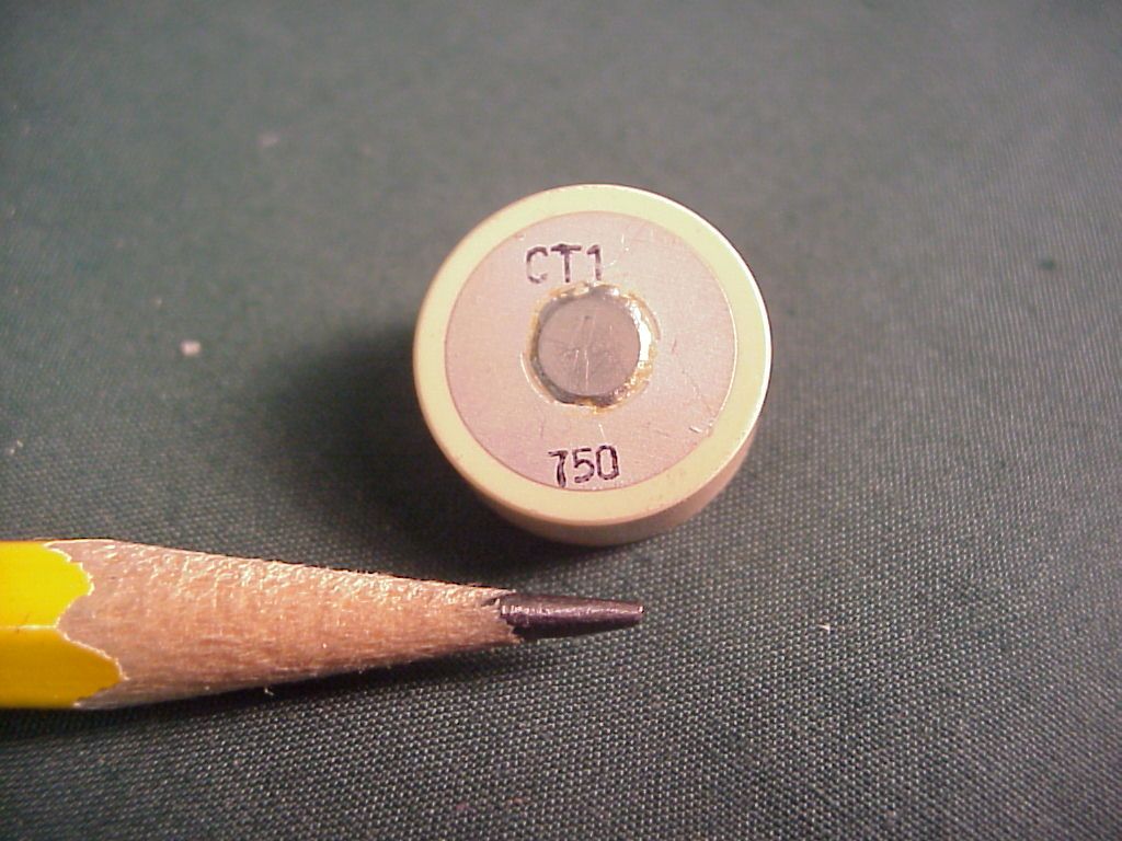
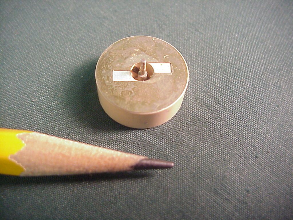
Regulatory Approvals Group March 6, 2001 LXE, Inc. 125 Technology Parkway Norcross, GA 30092-9200 USA TEL: (770) 447-4224 FAX: (770) 447-6928 EMAIL: [email protected] Federal Communications Commission Equipment Authorization Division, Application Processing Branch 7435 Oakland Mills Road Columbia, MD 21046 RE: KDZLXE6526M Form 731: EA99590 Correspondence Number: 18289 Dear Mr. Dichoso: In response to your inquiry, I have prepared the following reply: Item #1 The processing gain data reflects all available data rates. They include 1, 2, 5.5 and 11Mbps. This can be verified by looking at the top margin of the data pages. The data rate is given in that location. Items #2 On the contrary, we wish to have the card approved independent of the terminals identified in the reports. The terminals were identified only to show the intended operating configuration of the radio so that the commission can make an assessment of RF exposure requirements. This information has been requested on past applications, so we included it with this application to keep delays to a minimum. Compliance with the modular requirements is attested to below: 1) The radio card employs its only RF shielding. This can be verified in the photographs already submitted. 2) The modulation/data inputs are all buffered to prevent over-modulation and to ensure compliance with part 15 requirements. 3) The module is regulated at 5Vdc. 4) The module complies with 15.203 and 15.204(c). The radio module itself is equipped with and MMCX connector. All antennas identified in the report all use this connector or another connector considered unique. For reference the antennas are listed below with their connector type: • 155104-0001 0dBi Omni integrated antenna utilizing MMCX connector. One of 2 antennas used on LXE MX1 hand-held terminal. • 154591-0001 0dBi Patch integrated antenna utilizing MMCX connector. Second of 2 antennas used on LXE MX1 hand-held terminal. • 990004-0027 1.8 dBi Omni external antenna utilizing MMCX connector via cable from antenna to radio module. This antenna is used with the LXE model 2325 hand-held terminal. • Toko Model DAC2450CT1 2.15 Omni integrated antenna. This antenna is used with the LXE Model MX2 hand-held terminal and is soldered to the board. Regulatory Approvals Group March 6, 2001 LXE, Inc. 125 Technology Parkway Norcross, GA 30092-9200 USA TEL: (770) 447-4224 FAX: (770) 447-6928 EMAIL: [email protected] • 153180-0001 0dBi Omni external antenna equipped with R-TNC connector. This antenna is used on al models of LXE Vehicle Mount terminals. Models include the 1380 and 1390, VX1 and VX2, and the 1590. In accordance with 15.204(c), no antennas other than the ones identified above will be used with the radio module. 5) The module was tested in the PCMCIA slot of a laptop PC independent of the terminals identified in the report. This configuration provided exact interconnect conditions between the radio and all host devices via the PCMCIA bus and was considered worst for emissions since the PCMCIA slot was left open whereas the host terminal devices will enclose the radio completely. 6) Both the radio and the host terminal are labeled with the FCC Identifier. Sample labels have been included with the original submittal. 7) The module complies with all of the requirements applicable to it as shown in the test report. 8) An extensive explanation was submitted with the original filing showing how the module complies with the RF safety requirements applicable to it. The integration of this radio module is completely controlled by LXE. The radio card itself is not made available to customers except as direct replacements for damaged radios. These replacement radios are programmed with firmware specific to the terminals in which they are installed. Item # 3 See item #2, bullet number 4 above. Item #4 As a result of recent permissive change applications for FCC ID’s: KDZ480628-4096, KDZ 480824-3300 and KDZLXE4810P3S01US, all manuals are currently in revision to include new RF safety statements and are not yet available for review. The statements, however are as follows: For portable devices intended for use in the hand only and not on any part of the rest of the body, the following statement is included: Caution This device is intended to transmit RF energy. In accordance with FCC radio- frequency safety regulations, this device is certified for hand-held operation only. A minimum separation distance of at least 20cm from the users body and nearby persons should be maintained during transmission. Use of this device not consistent with these instructions can increase the risk of RF exposure. Regulatory Approvals Group March 6, 2001 LXE, Inc. 125 Technology Parkway Norcross, GA 30092-9200 USA TEL: (770) 447-4224 FAX: (770) 447-6928 EMAIL: [email protected] For mobile devices intended to be used greater than 20cm from the user, the following statement will appear in those installation manuals: Caution This device is intended to transmit RF energy. For protection against RF exposure to humans and in accordance with FCC rules, this transmitter should be installed such that a minimum separation distance of at least 20cm is maintained between the antenna and the general population Item #5 A separate certification is being sought for this same radio module for use in a body worn application. Due to difficulties experienced on the previous filings mentioned above, separate certifications were deemed necessary to avoid having to justify mixed use of this radio module. We were advised by Kwok Chan that mixed use applications, although possible in some cases, run the risk of dismissal. Our schedule will not permit this, therefore it was decided to file separate certifications. Mr. Chan also advised that, hand-held only, portable devices could be included in mobile certifications due to higher SAR limits for the hands. We trust we have satisfactorily addressed the issues you raised in this correspondence. Sincerely, R. Sam Wismer…
Text truncated - open the document above for the full version.
ID Label/Location Info
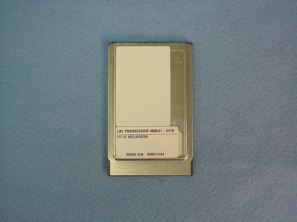
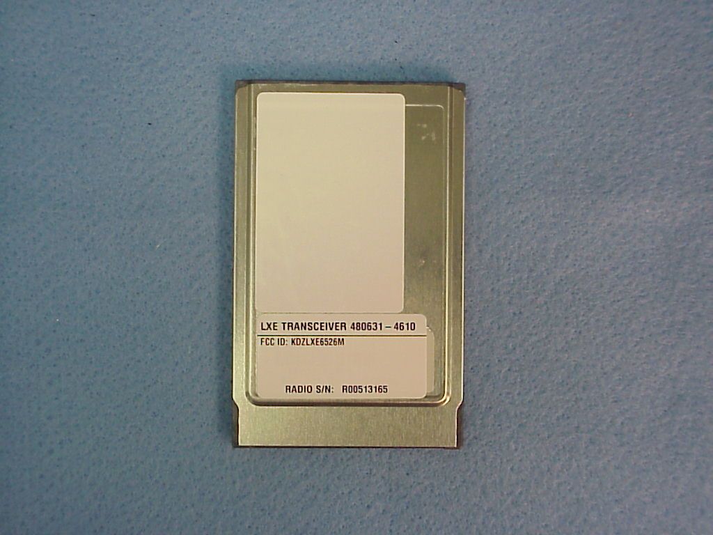
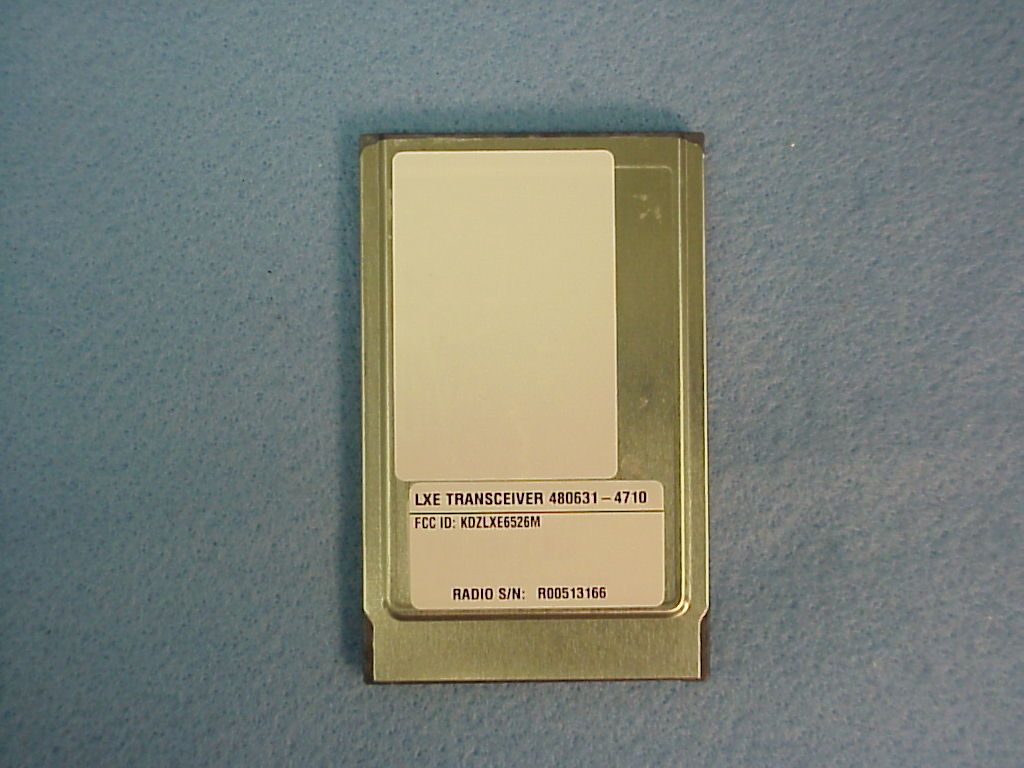
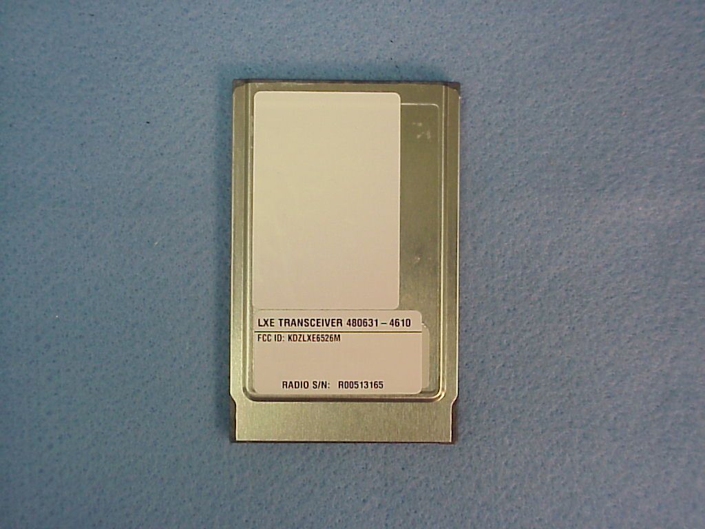
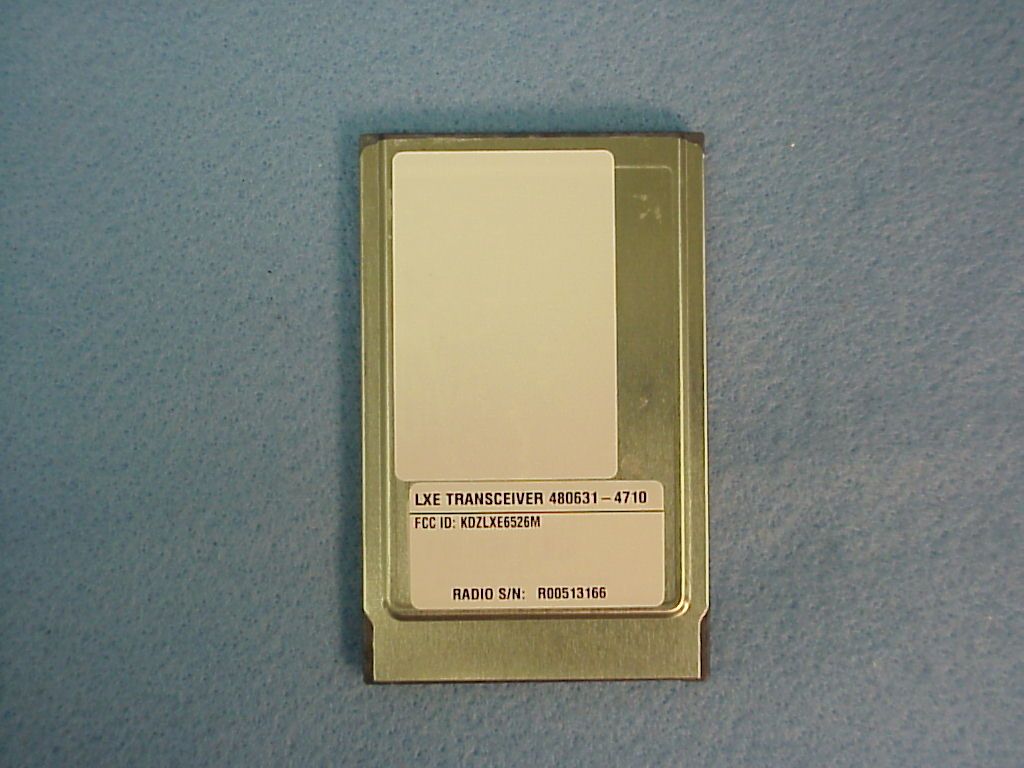
Regulatory Approvals Group January 16, 2001 LXE, Inc. 125 Technology Parkway Norcross, GA 30092-9200 USA TEL: (770) 447-4224 FAX: (770) 447-6928 EMAIL: [email protected] Federal Communications Commission Equipment Authorization Division, Application Processing Branch 7435 Oakland Mills Road Columbia, MD 21046 RE: KDZLXE6526M Form 731: EA99590 Correspondence Number: 17693 Dear Ms. Elliot: In response to your inquiry, I have prepared the following reply: Item #1 I have uploaded example photographs of the labels for each variation of the LXE Model 6526 transceiver. The three variations differ only in their degree of encryption capability. The transmitter portion of the radio card is identical for all three variations. They include: P/N: 480631-4710 - No Encryption P/N: 480631-4410 - 40 Bit Encryption P/N: 480631-4610 - 128 Bit Encryption Items #2 & 3 Since the radio card is small and will be installed in a host device at all times, we included the FCC label information in the manual’s of each host device. A statement will appear on the radio advising the user to reference the manual for this information. The manual also contains the required manual information. I have uploaded a page from the manual of one of our terminal devices that will use this radio card. The FCC ID will appear on the label as shown in the photographs Sincerely, R. Sam Wismer RF Approvals Engineer LXE, Inc.
Test Report
Aironet Confidential 1 01/02/01 Aironet Confidential 2 01/02/01 PRODUCT NAME:Cisco Systems AIR-LMC34X RADIO NAME OF TEST:The Processing Gain of a Direct Sequence System. FCC Part 15.247 (e) specifies: The processing gain of a direct sequence system shall be at least 10 dB. Guidance on measurement by FCC The processing gain may be measured using the CW jamming margin method. The test consists of stepping a signal generator in 50khz increments across the passband of the system. At each point, the generator level required to the produce the recommended Bit Error Rate (10-5) is recorded. This is the jammer level. The output power of the transmitting unit is measured at the same point. The Jammer to Signal (J/S) ratio is then calculated. Discard the worst 20% of the J/S data points. Total losses in a system including transmitter and receiver, should be assumed to be no more than 2 dB. therefore, processing gain = S/N + Mj + Lsys Where : S/N = Signal to noise ratio required at the receiver output for 10-5 error rate of a ideal receiver for your demodulation scheme Mj = Jammer to signal ratio Lsys = System losses (2dB max) Test results : for 1 mb data rate: S/N = 13 dB ; taken from Wireless Information Networks by Pahlavan & Levesque Mj = - 4.2 dB ; worst case jamming margin from tests in lab Lsys = 2.0 dB ; system losses therefore the processing gain at 1mb is 13 dB - 4.2 dB + 2.0 dB = 10.8 dB for 2 mb data rate: S/N = 13 dB ; taken from Wireless Information Networks by Pahlavan & Levesque Mj = - 4.2 dB ; worst case jamming margin from tests in lab Lsys = 2.0 dB ; system losses therefore the processing gain at 2mb is 13 dB – 4.2 dB + 2.0 dB = 10.8 dB Aironet Confidential 3 01/02/01 for 5.5 mb data rate: S/N = 13.6 dB ; taken from Harris CCK encoding modulation Mj = - 4.4 dB ; worst case jamming margin from tests in lab (after 20% discard) Lsys = 2.0 dB ; system losses therefore the processing gain at 5.5mb is 13.6 dB - 4.4 dB + 2.0 dB = 11.2 dB for 11 mb data rate: S/N = 16.0 dB ; taken from Harris CCK encoding modulation Mj = - 7.4 dB ; worst case jamming margin from tests in lab (after 20% discarded) Lsys = 2.0 dB ; system losses therefore the processing gain at 11mb is 16.0 dB - 7.4 dB + 2.0 dB = 10.6 dB Aironet Confidential 4 01/02/01 AI RONET CONFI DENTIAL RF Systems Engi neering dwg: J. Friedmann Fil e:FCC025_2.ds4 Date: 3/21/96 rev: 2. 4 Ghz SPREAD SPECTRUM RADI O, 2nd GEN Jammer Test, R240 eng: J. Friedmann Transmitter Jamming Test Setup AI RONET Si g GenPower Met er Recei ver Bit Error Rate Tester splitsum Aironet Confidential 5 01/02/01 LM340 Spread Spectrum Transceiver Alignment Procedures Set power out: put radio in TX mode, use power meter to set power out. 1)TX on,ch 12-84: set power amp output power by adjusting voltage to the IF attenuator in the tx chain. This is done by software, which changes the DAC voltage output. TX power out; set power to +15dBm + 1dB /-1 dB for highest power setting
Test Report
CISCO CONFIDENTIALMercury processing gainJ. Friedmann data ratesmodulation usedsymbol rateschip ratechip per bit 10 log (chip per bit) add 3dB if unique codes for I & Q (minus 1 dB for implementation) theoretical processing gain dB (add last two columns) measured processing gain 1 mb/sBPSK1 mbps11 mbps 11 (same code for I & Q)10.7 dB10.7 dB10.8 dB 2 mb/sQPSK1 mbps11 mbps 11 (same code for I & Q)10.7 dB10.7 dB10.8 dB 5.5 mb/sCCK1.375 mbps8 mbps 8 (8 for I & 8 for Q)9 dB2 dB11 dB10.7 dB 11 mb/sCCK1.375 mbps8 mbps 8 (8 for I & 8 for Q)9 dB2 dB11 dB10.6 dB 9/25/001PG_Mercury_th_writeup.xls
Contact Information
Applicant
Mandana Salahshour(Global Regulatory Compliance Manager)
Test Firm
LXE Inc.Cyril Binnom
Technical Specifications
| # | Rule Parts | Frequency Range | Power Output |
|---|---|---|---|
| 1 | 15C | 2.41 GHz - 2.46 GHz | 25.00 mW |
Other Applications from Honeywell International, Inc.
KDZVM2C02
Apr 18, 2013Vehicle Mount Terminal
Equipment Class
DSS - Part 15 Spread Spectrum Transmitter
KDZVM2W02
Apr 18, 2013Vehicle Mount Terminal
Equipment Class
PCB - PCS Licensed Transmitter
KDZVM2W01
Apr 17, 2013Vehicle Mount Terminal
Equipment Class
DSS - Part 15 Spread Spectrum Transmitter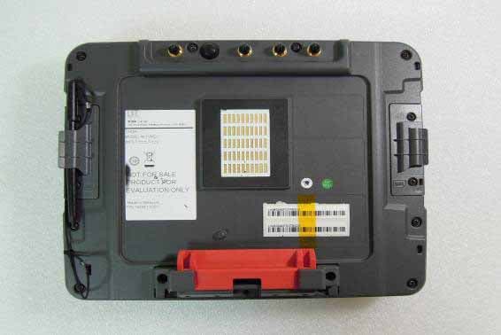
KDZVM2C01
Apr 17, 2013Vehicle Mount Terminal
Equipment Class
DTS - Digital Transmission System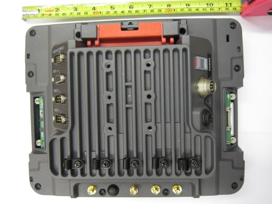
KDZLXE-VM1
Jun 22, 2011Wireless Vehicle Mount Terminal
Equipment Class
DTS - Digital Transmission System