KDZLXE6526PClass A Device
Honeywell International, Inc.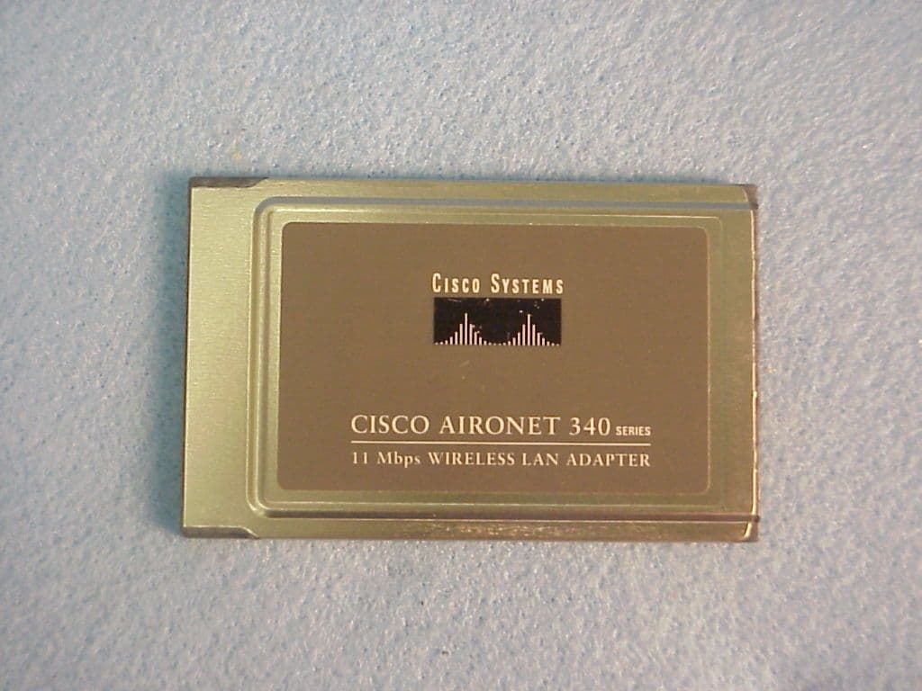
Click to zoom
Application Details
- Equipment Class
- DSS - Part 15 Spread Spectrum Transmitter
- Date of Grant
- Mar 26, 2001
- Application Purpose
- Original Equipment
- Date of Application
- Dec 17, 2000
- Equipment Note
- Class A Device
- Frequency Range
- 2412.00000000 - 2462.00000000
- Country
- United States
Documents & Files
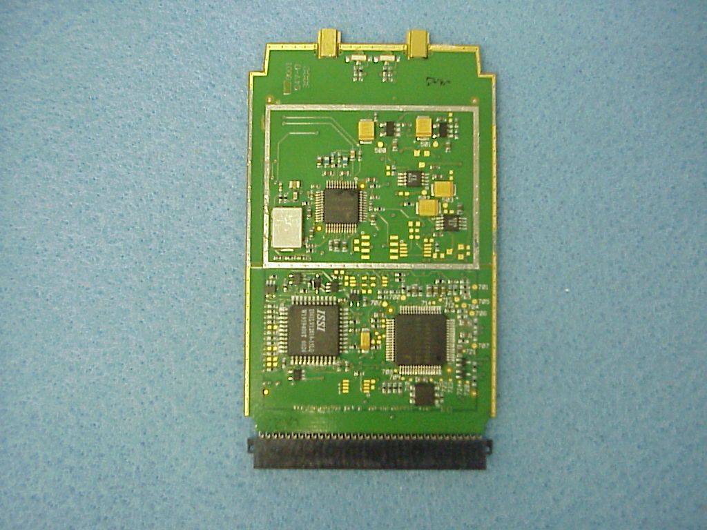
Document Text
Text extracted from the exhibit documents filed with the FCC. Open a document above to read the original.
Cover Letter(s)
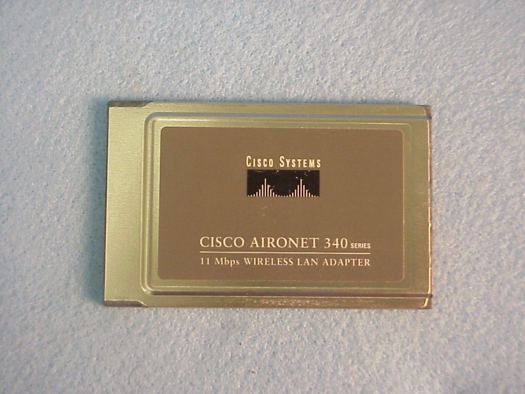
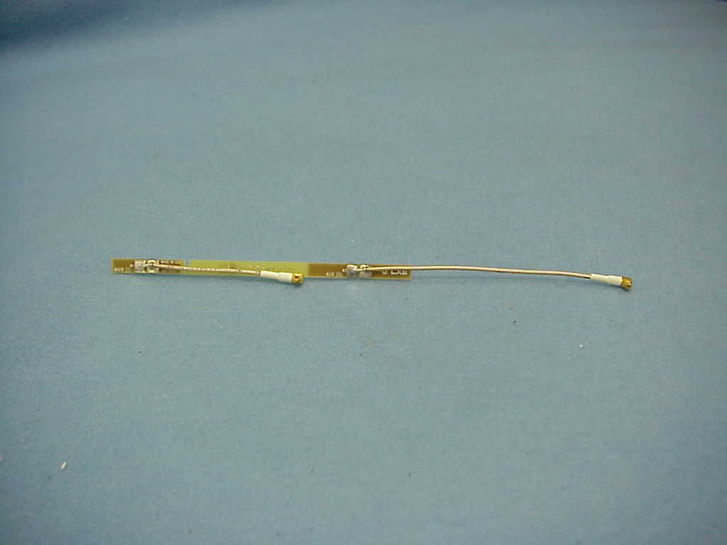
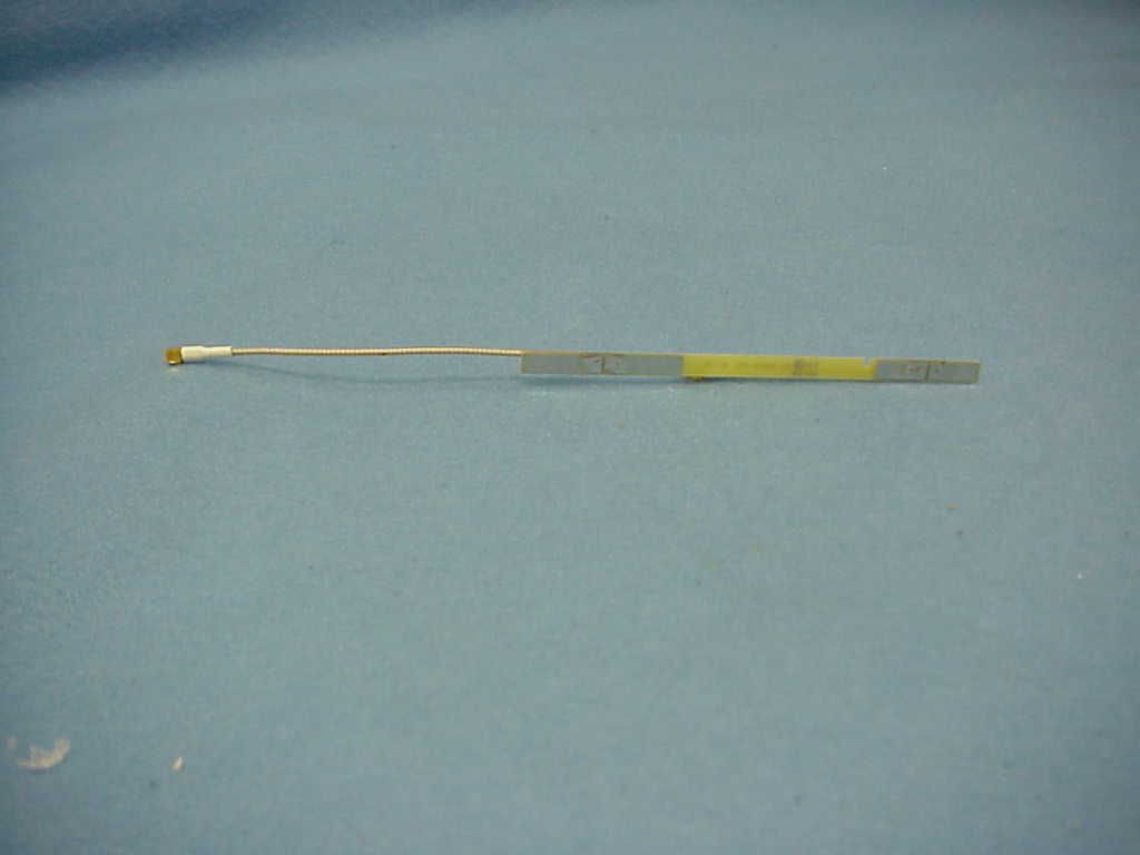
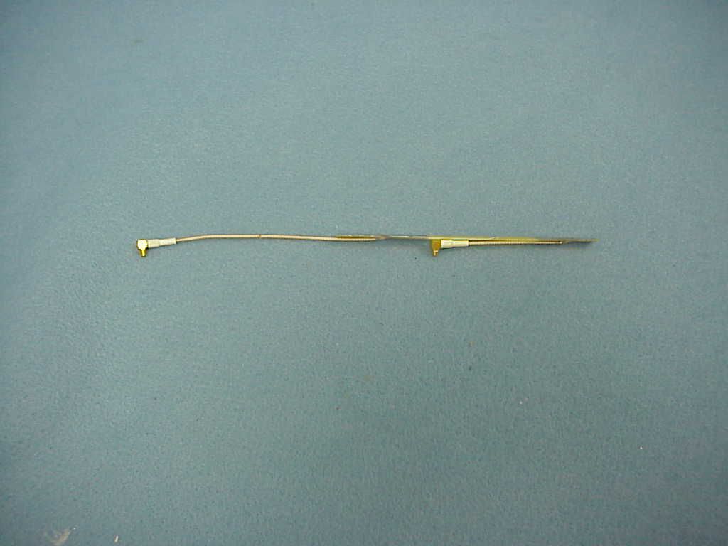
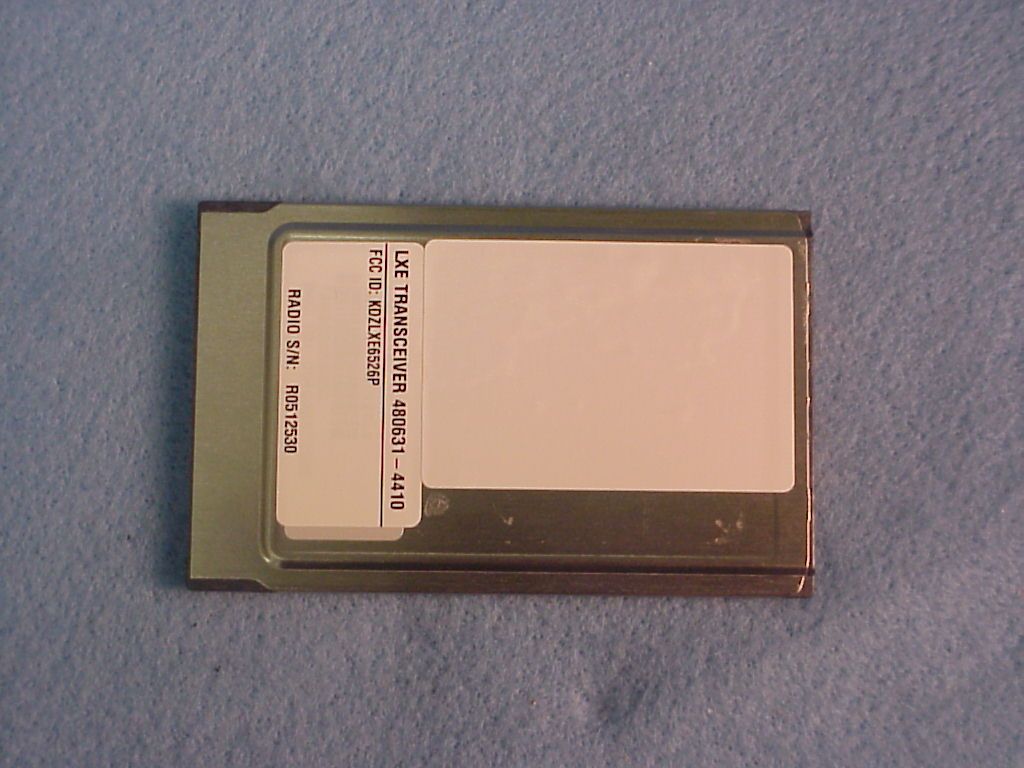
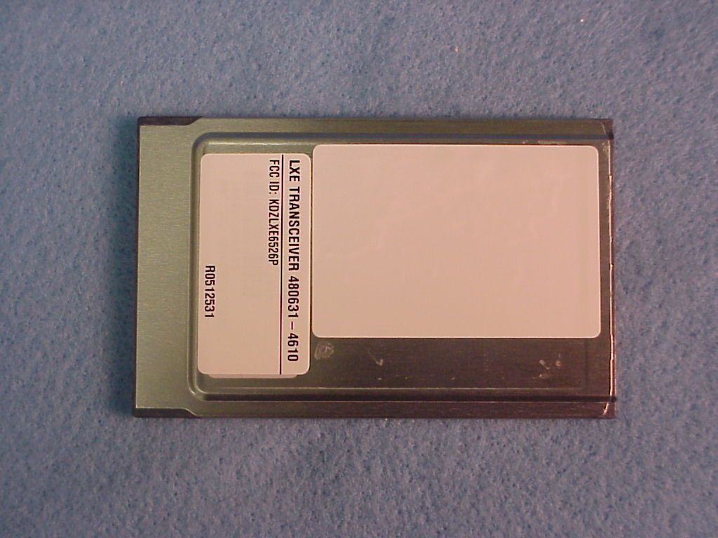
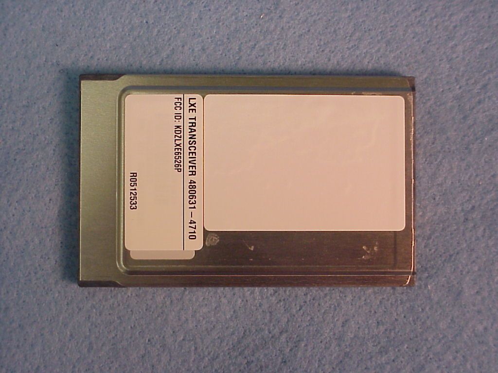
Regulatory Approvals Group February 9, 2001 LXE, Inc. 125 Technology Parkway Norcross, GA 30092-9200 USA TEL: (770) 447-4224 FAX: (770) 447-6928 EMAIL: [email protected] Federal Communications Commission Equipment Authorization Division, Application Processing Branch 7435 Oakland Mills Road Columbia, MD 21046 RE: KDZLXE6526P Form 731: EA99542 Correspondence Number: 18027 Dear Mr. Dichoso: In response to your inquiry, I have prepared the following reply. Inquiry Item # 1 I have asked David Case of Cisco Systems to itemize the items he considers confidential. He advise that he will fax it in. Inquiry Item # 2 I have uploaded data supplied to me from Cisco System. The file is titled Pgain Data.pdf Inquiry Item # 3 I have uploaded data supplied to me from Cisco Systems. The file is titled Pgain Theory.pdf Inquiry Item # 4 The 6526P transceiver is intended for Class A environments only. It is integrated into our terminals here at our factory and is not available for sale to the general public. The radios can be sold separately to our customers as replacements for existing radios, however the radios are coded prior to shipping, for the terminals they are to be installed in. They cannot work in a host device for which it is not programmed or intended for use. Inquiry Item # 5 Antenna photos have been uploaded. I apologize for this omission. Regulatory Approvals Group February 9, 2001 LXE, Inc. 125 Technology Parkway Norcross, GA 30092-9200 USA TEL: (770) 447-4224 FAX: (770) 447-6928 EMAIL: [email protected] Inquiry Item # 6 On the contrary, we seek authorization on the card itself. The card was tested in a laptop computer as is shown in the test set-up photos. The laptop was used only to run the software to operate the radio card. We supplied host information for RF safety evaluation by Kwok Chan. On recent applications, he requested us to show the operating configuration and exposure conditions for each host device and in effort to prevent delay, we included that information in this filing prior to him asking for it. Currently this radio is slated for 2 hosts, the LXE MX3, and MX3-CE(Identified in the test report as the CX1). Both the MX3 and MX3-CE use the same antenna as they share the same form factor, but have different operating systems. Inquiry Item # 7 The antenna couples to the radio card via an MMCX connector. The antenna is integral to the host device and is not accessible to the user. We believe this configuration complies with 15.203 of the rules. Inquiry Item # 8 This is a portable certification. I have read through the report and cannot find any reference to mobile equipment. The cover letter, the report cover and section 1.2.1 of the report all identify this application as being a portable certification. The host devices mentioned above, is offered with a “Hip-Flip” that allows the users to use it from the hip area. In this configuration, the antenna is 15cm from the user. A mobile certification is also in process for this very same radio for use with our mobile and fixed devices as defined by section 2.1091 of the rules. That radio has been given the model number 6526M and will bare FCC ID: KDZLXE6526M. It is currently under review and has been assigned 731 Confirmation number EA99590 Let me know if you require anything else. Sincerely, R. Sam Wismer RF Approvals Engineer LXE, Inc.
Cover Letter(s)
Regulatory Approvals Group March 12, 2001 LXE, Inc. 125 Technology Parkway Norcross, GA 30092-9200 USA TEL: (770) 447-4224 FAX: (770) 447-6928 EMAIL: [email protected] Federal Communications Commission Equipment Authorization Division, Application Processing Branch 7435 Oakland Mills Road Columbia, MD 21046 RE: KDZLXE6526P Form 731: EA99542 Correspondence Number: 18306 Dear Mr. Dichoso: In response to your inquiry, I have prepared the following reply: Item #1 Users manuals are currently in revision to add RF safety instructions to the user. They are not yet available for review, however, the following statements will be included instructing the user for correct use to ensure RF exposure compliance: Caution This device is intended to transmit RF energy. In accordance with FCC radio-frequency safety regulations, when operating this device with the Hip-Flip accessory, it should be used in accordance with the users instructions. Additionally, the user should take care to ensure that a minimum separation distance of 20cm is maintained from the antenna to nearby persons. Use of this device in a manner not consistent with these instructions can increases the risk of RF exposure. Item #2 Noted. Thank you. The proposed grant conditions are acceptable. We trust we have satisfactorily addressed the issues you raised in this correspondence. Sincerely, R. Sam Wismer RF Approvals Engineer Regulatory Approvals Group March 12, 2001 LXE, Inc. 125 Technology Parkway Norcross, GA 30092-9200 USA TEL: (770) 447-4224 FAX: (770) 447-6928 EMAIL: [email protected] LXE, Inc.
Test Report
Aironet Confidential 1 01/02/01 Aironet Confidential 2 01/02/01 PRODUCT NAME:Cisco Systems AIR-LMC34X RADIO NAME OF TEST:The Processing Gain of a Direct Sequence System. FCC Part 15.247 (e) specifies: The processing gain of a direct sequence system shall be at least 10 dB. Guidance on measurement by FCC The processing gain may be measured using the CW jamming margin method. The test consists of stepping a signal generator in 50khz increments across the passband of the system. At each point, the generator level required to the produce the recommended Bit Error Rate (10-5) is recorded. This is the jammer level. The output power of the transmitting unit is measured at the same point. The Jammer to Signal (J/S) ratio is then calculated. Discard the worst 20% of the J/S data points. Total losses in a system including transmitter and receiver, should be assumed to be no more than 2 dB. therefore, processing gain = S/N + Mj + Lsys Where : S/N = Signal to noise ratio required at the receiver output for 10-5 error rate of a ideal receiver for your demodulation scheme Mj = Jammer to signal ratio Lsys = System losses (2dB max) Test results : for 1 mb data rate: S/N = 13 dB ; taken from Wireless Information Networks by Pahlavan & Levesque Mj = - 4.2 dB ; worst case jamming margin from tests in lab Lsys = 2.0 dB ; system losses therefore the processing gain at 1mb is 13 dB - 4.2 dB + 2.0 dB = 10.8 dB for 2 mb data rate: S/N = 13 dB ; taken from Wireless Information Networks by Pahlavan & Levesque Mj = - 4.2 dB ; worst case jamming margin from tests in lab Lsys = 2.0 dB ; system losses therefore the processing gain at 2mb is 13 dB – 4.2 dB + 2.0 dB = 10.8 dB Aironet Confidential 3 01/02/01 for 5.5 mb data rate: S/N = 13.6 dB ; taken from Harris CCK encoding modulation Mj = - 4.4 dB ; worst case jamming margin from tests in lab (after 20% discard) Lsys = 2.0 dB ; system losses therefore the processing gain at 5.5mb is 13.6 dB - 4.4 dB + 2.0 dB = 11.2 dB for 11 mb data rate: S/N = 16.0 dB ; taken from Harris CCK encoding modulation Mj = - 7.4 dB ; worst case jamming margin from tests in lab (after 20% discarded) Lsys = 2.0 dB ; system losses therefore the processing gain at 11mb is 16.0 dB - 7.4 dB + 2.0 dB = 10.6 dB Aironet Confidential 4 01/02/01 AI RONET CONFI DENTIAL RF Systems Engi neering dwg: J. Friedmann Fil e:FCC025_2.ds4 Date: 3/21/96 rev: 2. 4 Ghz SPREAD SPECTRUM RADI O, 2nd GEN Jammer Test, R240 eng: J. Friedmann Transmitter Jamming Test Setup AI RONET Si g GenPower Met er Recei ver Bit Error Rate Tester splitsum Aironet Confidential 5 01/02/01 LM340 Spread Spectrum Transceiver Alignment Procedures Set power out: put radio in TX mode, use power meter to set power out. 1)TX on,ch 12-84: set power amp output power by adjusting voltage to the IF attenuator in the tx chain. This is done by software, which changes the DAC voltage output. TX power out; set power to +15dBm + 1dB /-1 dB for highest power setting
Test Report
CISCO CONFIDENTIALMercury processing gainJ. Friedmann data ratesmodulation usedsymbol rateschip ratechip per bit 10 log (chip per bit) add 3dB if unique codes for I & Q (minus 1 dB for implementation) theoretical processing gain dB (add last two columns) measured processing gain 1 mb/sBPSK1 mbps11 mbps 11 (same code for I & Q)10.7 dB10.7 dB10.8 dB 2 mb/sQPSK1 mbps11 mbps 11 (same code for I & Q)10.7 dB10.7 dB10.8 dB 5.5 mb/sCCK1.375 mbps8 mbps 8 (8 for I & 8 for Q)9 dB2 dB11 dB10.7 dB 11 mb/sCCK1.375 mbps8 mbps 8 (8 for I & 8 for Q)9 dB2 dB11 dB10.6 dB 9/25/001PG_Mercury_th_writeup.xls
Contact Information
Applicant
Mandana Salahshour(Global Regulatory Compliance Manager)
Test Firm
LXE Inc.Cyril Binnom
Technical Specifications
| # | Rule Parts | Frequency Range | Power Output |
|---|---|---|---|
| 1 | 15C | 2.41 GHz - 2.46 GHz | 25.00 mW |
Other Applications from Honeywell International, Inc.
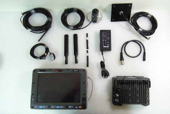
KDZVM2C02
Apr 18, 2013Vehicle Mount Terminal
Equipment Class
DSS - Part 15 Spread Spectrum Transmitter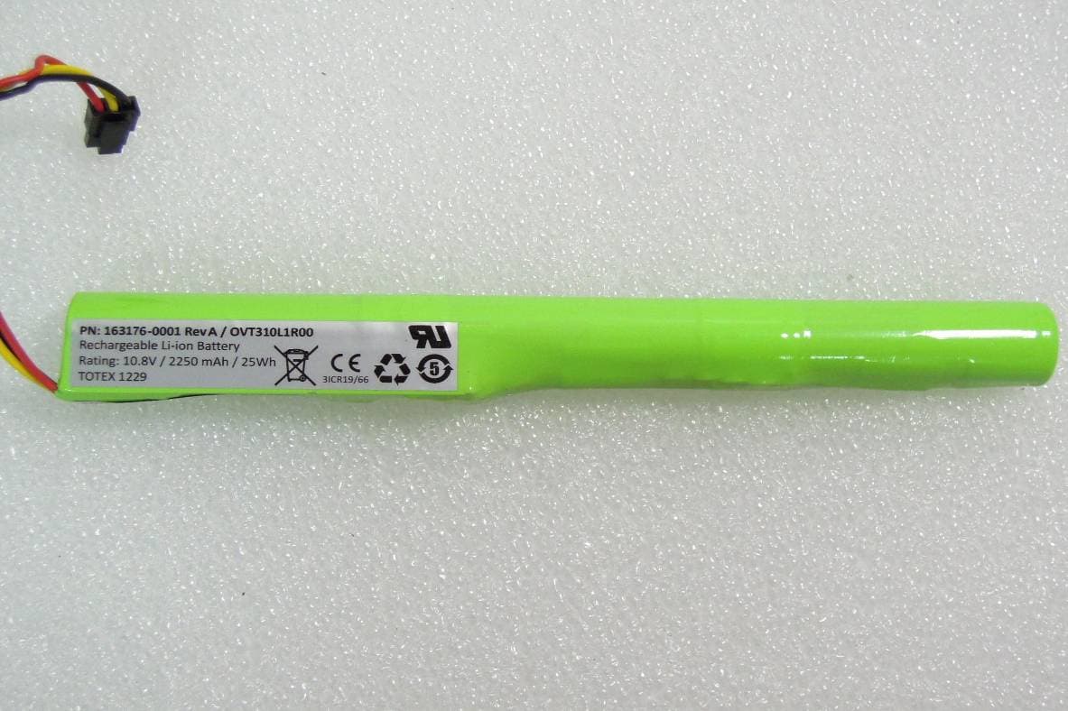
KDZVM2W02
Apr 18, 2013Vehicle Mount Terminal
Equipment Class
PCB - PCS Licensed Transmitter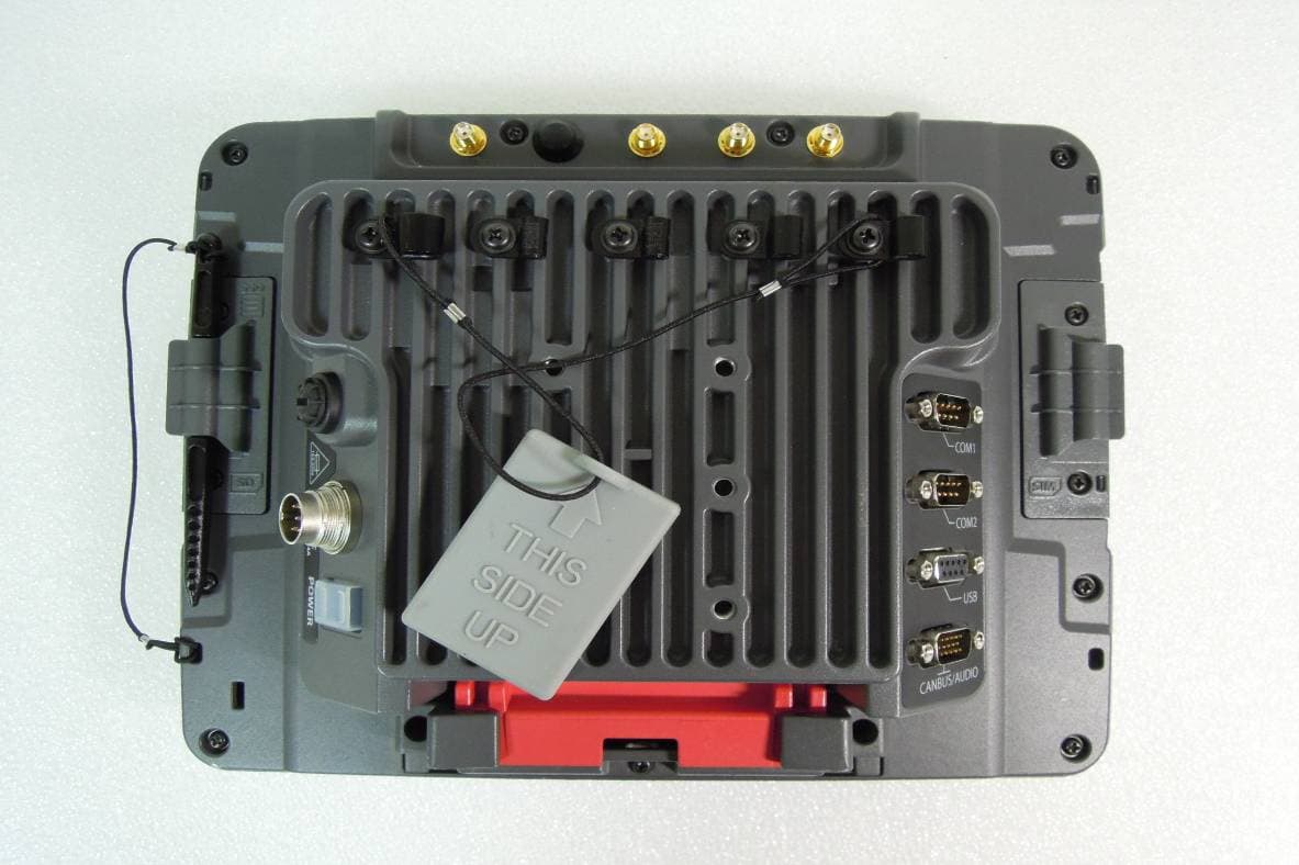
KDZVM2W01
Apr 17, 2013Vehicle Mount Terminal
Equipment Class
DSS - Part 15 Spread Spectrum Transmitter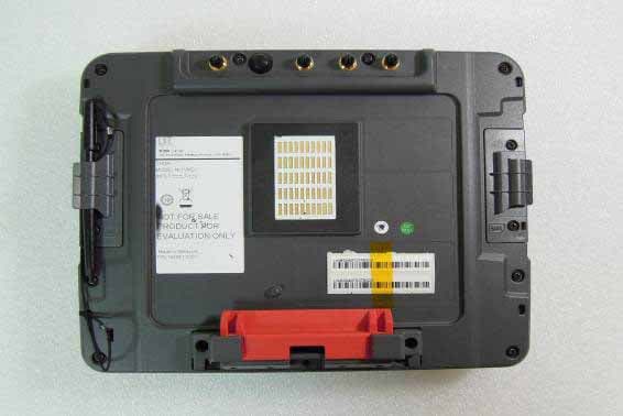
KDZVM2C01
Apr 17, 2013Vehicle Mount Terminal
Equipment Class
DTS - Digital Transmission System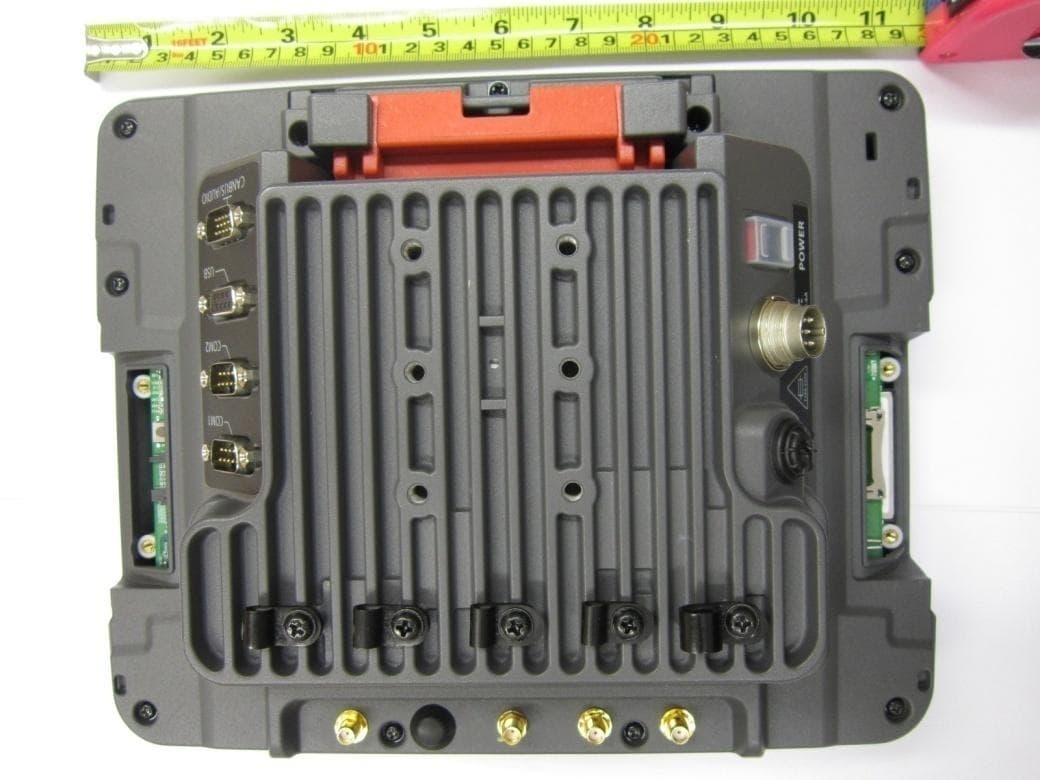
KDZLXE-VM1
Jun 22, 2011Wireless Vehicle Mount Terminal
Equipment Class
DTS - Digital Transmission System