KDZLXE6726P
Honeywell International, Inc.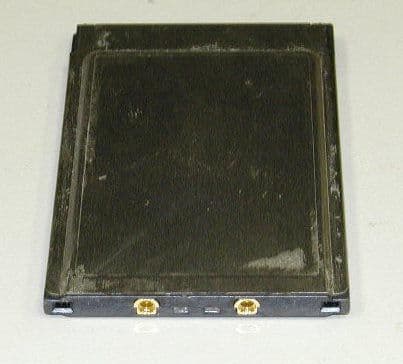
Click to zoom
Application Details
- Equipment Class
- DSS - Part 15 Spread Spectrum Transmitter
- Date of Grant
- Feb 27, 2002
- Application Purpose
- Original Equipment
- Date of Application
- Oct 16, 2001
- Frequency Range
- 2412.00000000 - 2462.00000000
- Country
- United States
Documents & Files
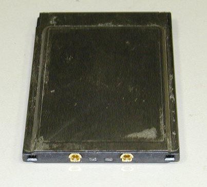
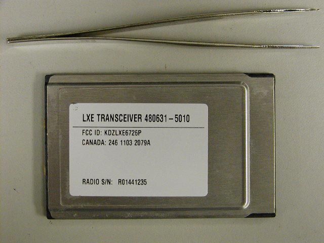
Document Text
Text extracted from the exhibit documents filed with the FCC. Open a document above to read the original.
Users Manual
LANGUAGE : ENGLISH Regulatory Notices Notice: LXE Inc. reserves the right to make improvements or changes in the products described in this manual at any time without notice. While reasonable efforts have been made in the preparation of this document to assure its accuracy, LXE assumes no liability resulting from any errors or omissions in this document, or from the use of the information contained herein. Copyright Notice: This manual is copyrighted. All rights are reserved. This document may not, in whole or in part, be copied, photocopied, reproduced, translated or reduced to any electronic medium or machine-readable form without prior consent, in writing, from LXE Inc. Copyright © 2001 by LXE Inc. An EMS Technologies Company. 125 Technology Parkway, Norcross, GA 30092 U.S.A. (770) 447-4224 LXE is a registered trademark of LXE Inc. Microsoft, Windows and the Windows logo are registered trademarks of Microsoft Corporation in the United States and/or other countries. All other brand or product names are trademarks or registered trademarks of their respective companies or organizations. When this manual is in PDF format: "Acrobat ® Reader Copyright © 1987-1999 Adobe Systems Incorporated. All rights reserved. Adobe, the Adobe logo, Acrobat, and the Acrobat logo are trademarks of Adobe Systems Incorporated." applies. FCC Information: This device complies with FCC Rules, part 15. Operation is subject to the following conditions: 1. This device may not cause harmful interference and 2. This device must accept any interference that may be received, including interference that may cause undesired operation. Note: This equipment has been tested and found to comply with the limits for a Class A digital device, pursuant to part 15 of the FCC rules. These limits are designed to provide reasonable protection against harmful interference when the equipment is operated in a commercial environment. This equipment generates, uses, and can radiate radio frequency energy and, if not installed and used in accordance with the instruction manual, may cause harmful interference to radio communications. Operation of this equipment in a residential area is likely to cause harmful interference in which case the user will be required to correct the interference at his own expense. Warning: Changes or modifications to this device not expressly approved by LXE, Inc., could void the user’s authority to operate this equipment. EMC Directive Requirements: This is a Class A product. In a domestic environment this product may cause radio interference in which case the user may be required to take adequate measures. Industry Canada: This Class A digital apparatus meets all requirements of the Canadian Interference Causing Equipment Regulations. Operation is subject to the following two conditions: (1) this device may not cause harmful interference, and (2) this device must accept any interference received, including interference that may cause undesired operation. Cet appareil numérique de la classe A respecte toutes les exigences du Règlement sur le matériel brouiller du Canada. Le present appareil numérique n’emet pas de bruits radioélectriques dépassant les limites applicables aux appareils numeriques de le Classe A préscrites dans le Reglement sur le brouillage radioélectrique édits par le ministere des Communications du Canada. Notice: The long term characteristics or the possible physiological effects of radio frequency electromagnetic fields have not been investigated by UL. RF Safety Notice: Caution: This device is intended to transmit RF energy. For protection against RF exposure to humans and in accordance with FCC rules and Industry Canada rules, this transmitter should be installed such that a minimum separation distance of at least 20 cm (7.8 in.) is maintained between the antenna and the general population.
Cover Letter(s)
Cisco Systems, Inc. 320 Springside Drive Akron, Ohio 44333 Phone: 330 664-7900 Fax: 330-664-7922 http://www.cisco.com November 5, 2001 Federal Communications Commission Equipment Authorization Division, Application Processing Branch 7435 Oakland Mills Road Columbia, MD 21046 RE: FCC ID: KDZLXE6726M / EA102762 and KDZLXE6726P / EA102766 To Whom It May Concern:: With this letter Cisco Systems, Inc. requests that the FCC utilize proprietary information included with FCC ID LDK102040 filing documentation in support of the following LXE, Inc. filings: KDZLXE6726M KDZLXE6726P EA102762 EA102766 In addition, Cisco Systems, Inc. requests that no proprietary information be released to LXE, Inc. as a result of this authorization. The radio module has not been modified in any manner. Best Regards, Jim Nicholson EMC Compliance Engineer
Cover Letter(s)
Cisco Systems, Inc. 320 Springside Drive Akron, Ohio 44333 Phone: 330 664-7900 Fax: 330-664-7922 http://www.cisco.com January 16, 2002 Federal Communications Commission Equipment Authorization Division, Application Processing Branch 7435 Oakland Mills Road Columbia, MD 21046 RE: FCC ID: KDZLXE6726M / EA102762 and KDZLXE6726P / EA102766 To Whom It May Concern: In support of the above listed LXE, Inc. filings, Cisco Systems Inc. requests that the following information be held confidential pursuant to 47 CFR Part 0 §0.457 and Section 552(b)(4) of the Freedom of Information Act, because the information provided is proprietary and contains trade secrets. If made public, the information might be used to the disadvantage of the applicant in the market place. Schematics Block Diagram Bills of Material Operational Description In addition, Cisco Systems, Inc. requests that no proprietary information be released to LXE, Inc. as a result of this authorization. The radio module has not been modified in any manner. Best Regards, Jim Nicholson EMC Compliance Engineer
Cover Letter(s)
An Technologies Company 125 Technology Parkway125 Technology Parkway Norcross, Georgia, US Norcross, Georgia, US 3009230092 (770) 447(770) 447--42244224 January 27, 2002 Joe Dichoso FCC Application Processing Branch Colombia, MD Dear Joe: This is in response to your request for additional information regarding FCC ID KDZLXE6726P, set forth in your correspondence reference number 21533. Regarding item : 1) External photos of host and antenna requested: New photo exhibit uploaded, entitled ‘Antenna photos’. 2) Updated RF Safety statement in our Operator’s Guides to state that the device is not to be co-located with other transmitters. Revised RF Safety Statement is shown here: Caution This device is intended to transmit RF energy. In accordance with FCC and Industry Canada radio frequency safety regulations, when operating this device with the Hip-Flip accessory, it should be used in accordance with the users instructions. Additionally, the user should take care to insure that a minimum separation distance of 20cm (7.8 in.) is maintained from the antenna to nearby persons. Use of this device not consistent with these instructions can increase the risk of RF exposure. This device is not to be co-located with other transmitters. 3) Confidential letter from Cisco requested; letter has been uploaded as exhibit. 4) In the RF Safety compliance report submitted, a distance of 15 cm is indicated between the radiating antenna in the MX3 and the user, when a hip-flip accessory is employed. In the RF Safety statement published in the MX3 Operators Guide, we recommend keeping a separation distance of 20 cm between the end of the MX3 and other people. The RF Safety statement published by LXE is more conservative than is required. See item 10 for further clarification. 5) Bandedge plots and data demonstrating compliance in the restricted band 2485.5 MHz – 2500 MHz have been uploaded as separate exibit, entitled ‘Addendum 1’. 6) The unique connector used is an MMCX type connector. 7) Output power – requested 100 mW, data shows 52 mW. Revised output power data uploaded as exhibit, entitled ‘Revised power levels’. 8) The device has two ports that do not transmit simultaneously. Data and plots of comparative conducted emissions between right and left ports has been uploaded as separate exhibit, entitled ‘Left vs right ports’. No notable difference between ports. l Page 2 January 27, 2002 9) Compliance with modular approval requirements: • The device was tested standalone, by utilizing a PCMCIA extender card that brings the EUT outside of the host PC. Additional test setup photo uploaded as exhibit. • The device has its own RF shielding. Internal shields can be viewed in the internal photo exhibit. External shield may be viewed in the external photo exhibit. • The device has its own voltage regulation – it cannot be operated over 5.5 Vdc input. • The device has its own data buffering. • The device complies with the antenna requirements of Section 15.203 & 15.204(c) by employing a smaller than normal footprint, MMCX type connector. When used in an Access Point host, the connector accessible is an R-TNC type. All antennas offered for sale with this device by LXE are included in the filing. 10) RF safety calculations: This filing includes only one host, the LXE MX3 series. (The device is filed separately for mobile hosts, under KDZLXE6726M). The MX3 employs a 0 dB patch antenna; the radio output power is 20 dBm. The MX3 may be used in a body-worn configuration, at the waist, used the “hip- flip” accessory. When used with the hip-flip acessory, the antenna is positioned at least 15 cm from the user’s body. To calculate the absolute worst-case distance that must be maintained to comply with MPE limits set forth in OET Bulletin 65, Table1: S ERP R π 64.1 = 1 )020(64.1 × + = π R R = 3.23 cm As can be seen from the calculation, when used with the hip-flip accessory, the transmitting antenna of the MX3 is positioned well beyond the MPE limits of compliance. 11) The radiated tests for this device were performed using a 6 dB patch antenna, in a PC host, with the transceiver installed on a PCMCIA extender card. The testing for this application is the same testing used for FCC ID KDZLXE6726M. It was judged that since the 6726 transceiver is a modular device, and that testing for the mobile grant included a configuration employing a 6 dB patch antenna, that the test data from that application could reasonably be used with this application. The MX3 host employs a 0 dB internal patch antenna. 12) Schematic, block diagram, and operational description has been uploaded as exhibits. 13) Processing gain data has been uploaded as a separate exhibit. Sincerely, D.C. Massey Lead Regulatory Engineer
External Photos
An Technologies Company 125 Technology Parkway125 Technology Parkway Norcross, Georgia, US Norcross, Georgia, US 3009230092 (770) 447(770) 447--42244224 LXE Model MX3-Series View into top showing antenna in endcap An Technologies Company 125 Technology Parkway125 Technology Parkway Norcross, Georgia, US Norcross, Georgia, US 3009230092 (770) 447(770) 447--42244224 MX3-Series Antenna, LXE P/N 157368-0001 : 0 dB patch antenna
Internal Photos
Internal view, topside with shields in place Internal view, topside, shields removed Internal view, bottom side with shields installed Internal view, bottom side with shields removed
RF Exposure Info
LXE, Inc. Model: 6726 FCC ID: KDZLXE6726P Appendix D RF Safety 125 Technology Parkway Norcross, Georgia, US 30092 RF Exposure Compliance Statement FCC 15.247(b)(4) & FCC 2.1093 Portable Devices LXE Model 6726 FCC ID: KDZLXE6726P LXE Project No: 01-074 LXE, Inc. Model: 6726 FCC ID: KDZLXE6726P LXE Project: 01-074 Page 2 LXE 6726 Transceiver The LXE 6726 is an OEM Direct Sequence Spread Spectrum product manufactured by Cisco Systems. It is IEEE 802.11b compliant and operates in the band of 2400-2483.5 GHz. The radio is capable of 4 data rates and self adjusts to the most appropriate rate depending on the performance required. The data rates are 11, 5.5, 2 and 1 Mbps, where 11 Mbps gives the maximum throughput for data transfer, and 1 Mbps gives the best coverage where only small data packets are sent. The radio has 2 ports, each cable of TX/RX operation. The card can be used either with a single antenna scheme in the main port, or a diverse antenna scheme using both ports. The conducted peak output power of the 6726 is 17.17 dbm Antenna The MX3 Series uses a proprietary, 0dBi patch antenna, identified as LXE P/N 157368-0001. Hip Use Accessory The MX3 Series is predominantly used as a hand-held device; however, an accessory item, called a “Hip- Flip”, allows the product to be used on a users hip. The following photographs illustrate the operating configuration and exposure conditions of the MX3 when used with a hip accessory. Typical Use 15.0cm LXE, Inc. Model: 6726 FCC ID: KDZLXE6726P LXE Project: 01-074 Page 3 Typical Hip Flip Operation Antenna Mounted in End Cap LXE, Inc. Model: 6726 FCC ID: KDZLXE6726P LXE Project: 01-074 Page 4 Antenna Endcap removed exposing antenna Transceiver 480628-4096 Transceiver Antenna LXE, Inc. Model: 6726 FCC ID: KDZLXE6726P LXE Project: 01-074 Page 5 RF Safety Conclusion Based on the low output power of the radio, the 0dBi gain of the antenna, and the location of the antenna relative to the user, we believe a SAR evaluation is not necessary. However, in an effort to advise the user of the potential risk of excessive exposure, we include the following statement in the MX3 manual: Caution This device is intended to transmit RF energy. In accordance with FCC and Industry Canada radio frequency safety regulations, when operating this device with the Hip-Flip accessory, it should be used in accordance with the users instructions. Additionally, the user should take care to insure that a minimum separation distance of 20cm (7.8 in.) is maintained from the antenna to nearby persons. Use of this device not consistent with these instructions can increase the risk of RF exposure.
RF Exposure Info
125 Technology Parkway Norcross, Georgia, US 30092 RF Exposure Compliance Statement FCC 15.247(b)(4) & FCC 2.1093 Portable Devices LXE Model 6726 FCC ID: KDZLXE6726P LXE Project No: 01-074 Amendment 1: Revised RF Safety Statement Issue Date: February 22, 2002 LXE, Inc. Model: 6726 FCC ID: KDZLXE6726P LXE Project: 01-074 Page 2 LXE 6726 Transceiver The LXE 6726 is an OEM Direct Sequence Spread Spectrum product manufactured by Cisco Systems. It is IEEE 802.11b compliant and operates in the band of 2400-2483.5 GHz. The radio is capable of 4 data rates and self adjusts to the most appropriate rate depending on the performance required. The data rates are 11, 5.5, 2 and 1 Mbps, where 11 Mbps gives the maximum throughput for data transfer, and 1 Mbps gives the best coverage where only small data packets are sent. The radio has 2 ports, each cable of TX/RX operation. The card can be used either with a single antenna scheme in the main port, or a diverse antenna scheme using both ports. The conducted peak output power of the 6726 is 19.29 dbm Antenna The MX3 Series uses a proprietary, 0dBi patch antenna, identified as LXE P/N 157368-0001. Hip Use Accessory The MX3 Series is predominantly used as a hand-held device; however, an accessory item, called a “Hip-Flip”, allows the product to be used on a users hip. The following photographs illustrate the operating configuration and exposure conditions of the MX3 when used with a hip accessory. Typical Use 15.0cm LXE, Inc. Model: 6726 FCC ID: KDZLXE6726P LXE Project: 01-074 Page 3 Typical Hip Flip Operation 15 cm Antenna Mounted in End Cap LXE, Inc. Model: 6726 FCC ID: KDZLXE6726P LXE Project: 01-074 Page 4 Antenna Endcap removed exposing antenna Transceiver Transceiver Antenna LXE, Inc. Model: 6726 FCC ID: KDZLXE6726P LXE Project: 01-074 Page 5 RF Safety Conclusion Based on the low output power of the radio, the 0dBi gain of the antenna, and the location of the antenna relative to the user, we believe a SAR evaluation is not necessary. However, in an effort to advise the user of the potential risk of excessive exposure, we include the following statement in the MX3 manual: Caution This device is intended to transmit RF energy. In accordance with FCC and Industry Canada radio frequency safety regulations, when operating this device with the Hip-Flip accessory, it should be used in accordance with the users instructions. Additionally, the user should take care to insure that a minimum separation distance of 20cm (7.8 in.) is maintained from the antenna to nearby persons. Use of this device not consistent with these instructions can increase the risk of RF exposure. Illustrations in the users’ manual show the user where the internal MX3 antenna is located.
Test Report
125 Technology Parkway Norcross, Georgia, US 30092 Test Report LXE Model: 6726 FCC ID: KDZLXE6726P Direct Sequence Spread Spectrum Transmitter Portable Equipment Certification Applicant: LXE Inc. 125 Technology Parkway Norcross, GA 30092 Purpose of Testing: To demonstrate compliance with FCC Part 15 Subpart C Prepared By: D. C. Massey Lead Regulatory Engineer Issue Date: October 17, 2001 Page 2 Table of Contents 1.0 General 3 1.1 Introduction 3 1.2 Product Description 3 1.2.1 General 3 1.2.2 Intended Use 3 1.2.3 Technical Specifications 4 1.2.4 Antenna 4 2.0 Location of Test Facility 4 2.1 Description of Test Facility 5 2.2 Radiated Test Site Illustration 5 3.0 Applicable Standards and References 6 4.0 List of Test Equipment 6 5.0 Support Equipment 6 6.0 EUT Setup Block Diagram 7 7.0 Summary of Tests 7 7.1 Section 15.203 - Antenna Requirement 7 7.2 Section 15.207 - Power Line Conducted Emissions 7 7.3 Section 15.209 - Radiated Emissions 7 7.4 Section 15.247(a)(2) - 6dB Bandwidth Requirement 8 7.5 Section 15.247(b) - Peak Output Power 8 7.6 Section 15.247(c) - Spurious Emissions 9 7.6.1 RF Conducted Spurious Emissions 9 7.6.2 Radiated Spurious Emissions(Restricted Bands) 9 7.7 Section 15.247(d) - Power Spectral Density 11 9.0 Processing Gain – 15.247(e) 12 10.0 Sample Label 12 11.0 RF Safety Statement 12 Appendix A - Conducted Spurious Emissions Appendix B - Radiated Spurious Emissions Appendix C - Processing Gain Report Appendix D - RF Safety Information LXE, Inc. Model: 6726 FCC ID: KDZLXE6726P Page 3 1.0 GENERAL 1.1 Introduction The purpose of this report is to demonstrate compliance with Part 15, Subpart C of the FCC’s Code of Federal Regulations. 1.2 Product Description 1.2.1 General The Equipment Under Test(EUT) is the LXE Model 6726, 2.4GHz Spread Spectrum transceiver. It is offered with 128 bit Wired Equivalent Privacy(WEP). The LXE part number for this radio model is 480631-5010; this part number will appear on the radio and on the host device labels, identifying the transceiver used in the host. The LXE 6726 is an OEM Direct Sequence Spread Spectrum product manufactured by Cisco Systems. It is IEEE 802.11b compliant and operates in the band of 2400-2483.5 GHz. The radio is capable of 4 data rates and self adjusts to the most appropriate rate depending on the performance required. The data rates are 11, 5.5, 2 and 1 Mbps, where 11 Mbps gives the maximum throughput for data transfer, and 1 Mbps gives the best coverage where only small data packets are sent. The radio has 2 ports, each capable of TX/RX. The card can be used either with a single antenna scheme in one port, or a diverse antenna scheme using both ports. The radio is housed in a PCMCIA Type II card. 1.2.2 Intended Use The LXE 6726 transceiver will be integrated into the MX3 Series products. The MX3 is defined as portable according to section 2.1093 of the FCC rules. A separate certification has been obtained for this same radio for LXE devices defined as mobile according to section 2.1091 of the FCC rules. The FCC ID for this certification is KDZLXE6726M. The MX3 Series is a handheld data collection terminal that accepts the 6526 radio in its PCMCIA slot. The MX3 Series encompasses a variety of terminal variations, with different options for memory, storage, operating system, software loads, and LCD display. The MX3 is considered portable because an accessory is offered that allows the operator to use the device from a hip position. In this configuration the antenna is approximately 15 cm from the users torso. Photographs of the operating configuration and exposure conditions are included separately in this filing as part of the RF exposure submittal. The MX3 has been evaluated to, and found to comply with, FCC Part 15, Subpart B, Class A. LXE, Inc. Model: 6726 FCC ID: KDZLXE6726P Page 4 1.2.3 Technical Specifications Table 1: Specifications Frequency Band 2400-2483.5 MHz Number of Channels 11 Modulation Technique BPSK 1 Mbps QPSK 2 Mbps CCK 5.5 and 11 Mbps Interface PC Card Type II Size Dimensions 85.0 mm X 53.95 mm X 5.0 mm (PC Card) Output power 14 dBm nominal Power Consumption PC Card Doze mode 10 mA Receive mode 280 mA Transit mode 400 mA at max output power Temperature Range (operational) 0-70ºC 95% max. humidity (non condensing) Operating Systems DOS Windows 95 Windows 98 Windows NT® Windows 2000 Standards IEEE 802.11b Regulations FCC Part 15 Subpart C RSS 139 & RSS 102 ETS 300 328 & 300 826 1.2.4 Antenna The MX3 Series uses a proprietary, 0dBi patch antenna, identified as LXE part number 157368-0001. 2.0 LOCATION OF TEST FACILTY The LXE test facility is located at the following address: LXE, Inc. An Electromagnetic Sciences Company 125 Technology Parkway Norcross, GA US 30092-2993 LXE, Inc. Model: 6726 FCC ID: KDZLXE6726P Page 5 2.1 DESCRIPTION OF OPEN AREA TEST SITE All tests were conducted at the manufacture’s test facility at a location specifically prepared for this testing. The radiated emissions test site meets the characteristics of ANSI C63.4:1992, CISPR 16 and EN 55022:1998-. This site has been fully described and submitted to the FCC, and accepted in their letter marked 31040/SIT, 1300F2. The open area test site(OATS) is located in the center of the rooftop of the building. The roof is located at a height of approximately 8 meters above the ground. The 3 meter radiated emissions test site is an open, flat area approximately 6.2m x 9.2m in dimension. All reflecting objects including test personnel lie outside the perimeter of the ellipse. The site has a ground plane which extends 2 meters past the mast and equipment under test(EUT). Material of the ground plane, comprised of individual 1/4” metal screen mesh rolls, were soldered at the seams with gaps smaller than 1/10 of the wavelength at 1000MHz. The ground plane is connected to the earth ground by ground rods. All wiring is done at floor level around the test site periphery. A nonconductive remotely controlled turntable approximately 0.91m x 1.2m x …
Text truncated - open the document above for the full version.
Test Report
125 Technology Parkway Norcross, Georgia, US 30092 Test Report LXE Model: 6726 FCC ID: KDZLXE6726P Direct Sequence Spread Spectrum Transmitter Portable Equipment Certification Applicant: LXE Inc. 125 Technology Parkway Norcross, GA 30092 Purpose of Testing: To demonstrate compliance with FCC Part 15 Subpart C Amendment 1: Revised output power levels Prepared By: D. C. Massey Lead Regulatory Engineer Issue Date: January 26, 2002 Revised power output levels from page 8: Table 5: Peak Output Power Measured Levels - S/N VMS05360111J Data Rate Channel 1 Channel 2 Channel 3 Correction (Mbs) Right Left Right Left Right Left Factors (dB) 1 19.98 19.74 18.51 18.42 17.78 17.8 Ch.1 0.5986 2 19.82 19.67 18.37 18.48 17.74 17.69 Ch.2 0.7347 5.5 19.95 19.88 18.46 18.42 17.92 17.78 Ch.3 0.6807 11 19.97 19.74 18.56 18.37 17.95 17.69 Corrected Levels - S/N VMS05360111J Data Rate Channel 1 Channel 2 Channel 3 Highest Power Level: 20.58dBm (Mbs) Right Left Right Left Right Left 114mW 1 20.58 20.34 19.11 19.02 18.38 18.40 2 20.42 20.27 18.97 19.08 18.34 18.29 Average Power Level: 19.29dBm 5.5 20.55 20.48 19.06 19.02 18.52 18.38 85 mW 11 20.57 20.34 19.16 18.97 18.55 18.29
Test Report
Document Number: ENG3707 Revision: A Supersedes: Issue Date: June 26, 2001 DATA SHEET Spurious Emissions - Conducted FCC Rule 15.247(c) LXE Project Number: 01-074 & 01-073 EUT Model Number: 6726 Technician: D. Massey Date of Test: 01/25/02 ANTENNA RIGHT PORT Requirement: 15.247(c) - In any 100 kHz bandwidth outside the frequency band in which the spread spectrum intentional radiator is operating, the radio frequency power that is produced by the intentional radiator shall be at least 20 dB below that in the 100 kHz bandwidth within the band that contains the highest level of the desired power, based on either an RF conducted or a radiated measurement. Attenuation below the general limits specified in § 15.209(a) is not required. Measured Results: Enter results obtained in the procedure in table 1. Fundamental Frequency Level 8.50 dB Table 1: Measurement Results Transmitting Channel Frequency (MHz) Level (dBm) Delta dB (dB) Pass/Fail 1 1085.0 -41.00 49.50 P 1 2396.8 -23.67 32.17 P 7 1435.0 -42.67 51.17 P 11 2373.0 -50.33 58.83 P 11 2484.5 -47.17 55.67 P 11 4923.3 -48.00 56.50 P Conclusion ______X____The EUT Satisfies the requirements of 15.247(c). __________ The EUT does not Satisfy the requirements of 15.247(c). Document Number: ENG3707 Revision: A Supersedes: Issue Date: June 26, 2001 DATA SHEET Spurious Emissions - Conducted FCC Rule 15.247(c) LXE Project Number: 01-074 & 01-073 EUT Model Number: 6726 Technician: D. Massey Date of Test: 01/25/02 ANTENNA LEFT PORT Requirement: 15.247(c) - In any 100 kHz bandwidth outside the frequency band in which the spread spectrum intentional radiator is operating, the radio frequency power that is produced by the intentional radiator shall be at least 20 dB below that in the 100 kHz bandwidth within the band that contains the highest level of the desired power, based on either an RF conducted or a radiated measurement. Attenuation below the general limits specified in § 15.209(a) is not required. Measured Results: Enter results obtained in the procedure in table 1. Fundamental Frequency Level 8.83 dB Table 1: Measurement Results Transmitting Channel Frequency (MHz) Level (dBm) Delta dB (dB) Pass/Fail 1 1447.0 -50.67 59.50 P 1 1915.0 -50.83 59.66 P 1 2397.0 -25.50 34.33 P 7 2004.3 -51.00 59.83 P 11 2007.0 -50.50 59.33 P 11 2483.5 -49.33 58.16 P 11 4923.8 -48.83 57.66 P Conclusion ______X____ The EUT Satisfies the requirements of 15.247(c). __________The EUT does not Satisfy the requirements of 15.247(c).
Test Report
125 Technology Parkway Norcross, Georgia, US 30092 Test Report LXE Model: 6726 FCC ID: KDZLXE6726P Direct Sequence Spread Spectrum Transmitter Portable Equipment Certification Applicant: LXE Inc. 125 Technology Parkway Norcross, GA 30092 Purpose of Testing: To demonstrate compliance with FCC Part 15 Subpart C Addendum1: Upper bandedge radiated emission data Prepared By: D. C. Massey Lead Regulatory Engineer Issue Date: January 27, 2002 HIGH FREQUENCY RADIATED EMISSIONS DATA SHEET Date: 01/23/02 Radio Part Number: 6726 Antenna Part Number: 480424-2411 6dB Patch Tested By: D.C. Massey LXE Project No. 01-073 & 01-074 Frequency Antenna Level Correction Corrected Corrected Margin Final Distance Factors Level Level Result (MHz) (m) (dBuV) (dB) (dBuV) (uV/m) (uV) (Pass/Fail) 2483.5 3 37.17 11.86 49.03 282.75 217.25 PASS 2486.7 3 36.00 11.87 47.87 247.51 252.49 PASS 2489.4 3 36.83 11.88 48.71 272.70 227.30 PASS 2491.7 3 36.33 11.89 48.22 257.75 242.25 PASS 2497.3 3 37.5 11.92 49.42 295.74 204.26 PASS Notes: Search antenna vertical at 146 cm.
Test Setup Photos
TEST SETUP PHOTOS KDZLXE6726P Test Setup With 6db PATCH Antenna
Contact Information
Applicant
Mandana Salahshour(Global Regulatory Compliance Manager)
Technical Contact
LXE, Inc.Douglas C Massey
[email protected]770-447-4224
125 Technology Parkway · Norcross, Georgia · United States
Non-Technical Contact
Cisco Systems, Inc.Jim Nicholson
www.cisco.com3306647900
Test Firm
LXE Inc.Cyril Binnom
Technical Specifications
| # | Rule Parts | Frequency Range | Power Output |
|---|---|---|---|
| 1 | 15C | 2.41 GHz - 2.46 GHz | 100.00 mW |
Other Applications from Honeywell International, Inc.
KDZVM2C02
Apr 18, 2013Vehicle Mount Terminal
Equipment Class
DSS - Part 15 Spread Spectrum Transmitter
KDZVM2W02
Apr 18, 2013Vehicle Mount Terminal
Equipment Class
PCB - PCS Licensed Transmitter
KDZVM2W01
Apr 17, 2013Vehicle Mount Terminal
Equipment Class
DSS - Part 15 Spread Spectrum Transmitter
KDZVM2C01
Apr 17, 2013Vehicle Mount Terminal
Equipment Class
DTS - Digital Transmission System
KDZLXE-VM1
Jun 22, 2011Wireless Vehicle Mount Terminal
Equipment Class
DTS - Digital Transmission System