KDZLXE6730MWIRELESS LAN ACCESS POINT
Honeywell International, Inc.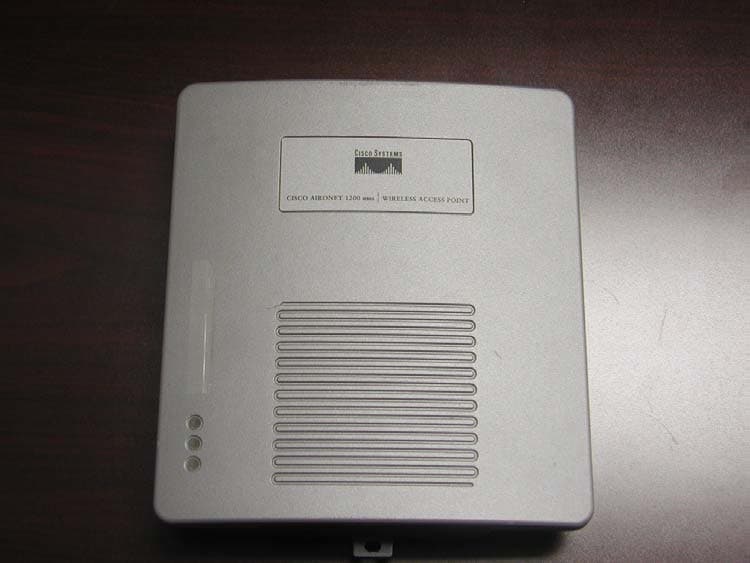
Click to zoom
Application Details
- Equipment Class
- DTS - Digital Transmission System
- Date of Grant
- Sep 24, 2003
- Application Purpose
- Original Equipment
- Date of Application
- Sep 24, 2003
- Equipment Note
- WIRELESS LAN ACCESS POINT
- Frequency Range
- 2412.00000000 - 2462.00000000
- Country
- United States
Documents & Files
Document Text
Text extracted from the exhibit documents filed with the FCC. Open a document above to read the original.
Users Manual
Corporate Headquarters Cisco Systems, Inc. 170 West Tasman Drive San Jose, CA 95134-1706 USA http://www.cisco.com Tel: 408 526-4000 800 553-NETS (6387) Fax: 408 526-4100 Cisco Aironet 1200 Series Access Point Hardware Installation Guide Customer Order Number: Text Part Number: OL-4310-01 THE SPECIFICATIONS AND INFORMATION REGARDING THE PRODUCTS IN THIS MANUAL ARE SUBJECT TO CHANGE WITHOUT NOTICE. ALL STATEMENTS, INFORMATION, AND RECOMMENDATIONS IN THIS MANUAL ARE BELIEVED TO BE ACCURATE BUT ARE PRESENTED WITHOUT WARRANTY OF ANY KIND, EXPRESS OR IMPLIED. USERS MUST TAKE FULL RESPONSIBILITY FOR THEIR APPLICATION OF ANY PRODUCTS. THE SOFTWARE LICENSE AND LIMITED WARRANTY FOR THE ACCOMPANYING PRODUCT ARE SET FORTH IN THE INFORMATION PACKET THAT SHIPPED WITH THE PRODUCT AND ARE INCORPORATED HEREIN BY THIS REFERENCE. IF YOU ARE UNABLE TO LOCATE THE SOFTWARE LICENSE OR LIMITED WARRANTY, CONTACT YOUR CISCO REPRESENTATIVE FOR A COPY. The following information is for FCC compliance of Class A devices: This equipment has been tested and found to comply with the limits for a Class A digital device, pursuant to part 15 of the FCC rules. These limits are designed to provide reasonable protection against harmful interference when the equipment is operated in a commercial environment. This equipment generates, uses, and can radiate radio-frequency energy and, if not installed and used in accordance with the instruction manual, may cause harmful interference to radio communications. Operation of this equipment in a residential area is likely to cause harmful interference, in which case users will be required to correct the interference at their own expense. The following information is for FCC compliance of Class B devices: The equipment described in this manual generates and may radiate radio-frequency energy. If it is not installed in accordance with Cisco’s installation instructions, it may cause interference with radio and television reception. This equipment has been tested and found to comply with the limits for a Class B digital device in accordance with the specifications in part 15 of the FCC rules. These specifications are designed to provide reasonable protection against such interference in a residential installation. However, there is no guarantee that interference will not occur in a particular installation. Modifying the equipment without Cisco’s written authorization may result in the equipment no longer complying with FCC requirements for Class A or Class B digital devices. In that event, your right to use the equipment may be limited by FCC regulations, and you may be required to correct any interference to radio or television communications at your own expense. You can determine whether your equipment is causing interference by turning it off. If the interference stops, it was probably caused by the Cisco equipment or one of its peripheral devices. If the equipment causes interference to radio or television reception, try to correct the interference by using one or more of the following measures: • Turn the television or radio antenna until the interference stops. • Move the equipment to one side or the other of the television or radio. • Move the equipment farther away from the television or radio. • Plug the equipment into an outlet that is on a different circuit from the television or radio. (That is, make certain the equipment and the television or radio are on circuits controlled by different circuit breakers or fuses.) Modifications to this product not authorized by Cisco Systems, Inc. could void the FCC approval and negate your authority to operate the product. The Cisco implementation of TCP header compression is an adaptation of a program developed by the University of California, Berkeley (UCB) as part of UCB’s public domain version of the UNIX operating system. All rights reserved. Copyright © 1981, Regents of the University of California. NOTWITHSTANDING ANY OTHER WARRANTY HEREIN, ALL DOCUMENT FILES AND SOFTWARE OF THESE SUPPLIERS ARE PROVIDED “AS IS” WITH ALL FAULTS. CISCO AND THE ABOVE-NAMED SUPPLIERS DISCLAIM ALL WARRANTIES, EXPRESSED OR IMPLIED, INCLUDING, WITHOUT LIMITATION, THOSE OF MERCHANTABILITY, FITNESS FOR A PARTICULAR PURPOSE AND NONINFRINGEMENT OR ARISING FROM A COURSE OF DEALING, USAGE, OR TRADE PRACTICE. IN NO EVENT SHALL CISCO OR ITS SUPPLIERS BE LIABLE FOR ANY INDIRECT, SPECIAL, CONSEQUENTIAL, OR INCIDENTAL DAMAGES, INCLUDING, WITHOUT LIMITATION, LOST PROFITS OR LOSS OR DAMAGE TO DATA ARISING OUT OF THE USE OR INABILITY TO USE THIS MANUAL, EVEN IF CISCO OR ITS SUPPLIERS HAVE BEEN ADVISED OF THE POSSIBILITY OF SUCH DAMAGES. Cisco Aironet 1200 Series Access Point Hardware Installation Guide Copyright © 2003 Cisco Systems, Inc. All rights reserved. CCIP, CCSP, the Cisco Arrow logo, the Cisco Powered Network mark, Cisco Unity, Follow Me Browsing, FormShare, and StackWise are trademarks of Cisco Systems, Inc.; Changing the Way We Work, Live, Play, and Learn, and iQuick Study are service marks of Cisco Systems, Inc.; and Aironet, ASIST, BPX, Catalyst, CCDA, CCDP, CCIE, CCNA, CCNP, Cisco, the Cisco Certified Internetwork Expert logo, Cisco IOS, the Cisco IOS logo, Cisco Press, Cisco Systems, Cisco Systems Capital, the Cisco Systems logo, Empowering the Internet Generation, Enterprise/Solver, EtherChannel, EtherSwitch, Fast Step, GigaStack, Internet Quotient, IOS, IP/TV, iQ Expertise, the iQ logo, iQ Net Readiness Scorecard, LightStream, MGX, MICA, the Networkers logo, Networking Academy, Network Registrar, Pa cke t, PIX, Post-Routing, Pre-Routing, RateMUX, Registrar, ScriptShare, SlideCast, SMARTnet, StrataView Plus, Stratm, SwitchProbe, TeleRouter, The Fastest Way to Increase Your Internet Quotient, TransPath, and VCO are registered trademarks of Cisco Systems, Inc. and/or its affiliates in the U.S. and certain other countries. All other trademarks mentioned in this document or Web site are the property of their respective owners. The use of the word partner does…
Text truncated - open the document above for the full version.
Users Manual
Engineering Notice LXE Inc. 125 Technology Parkway Norcross, GA 30092-2993 USA EN 700 Reason for Notice Product Release Authorization to Purchase Long Lead Parts Informational From: David Petree Date 9/17/03 Subject LXE 6730 RELEASE (Cisco AP1200) I. Overview This Engineering Notice contains special instructions for the use, setup, and Facility Analysis for the Cisco AP1200 (6730). This LXE release does not include the Cisco recently announced IOS version of the AP1200. II. Facility Analysis FA Limits There is no change to the cutoff limits using the AP1200 versus the AP350. Approved Antennas The following is the list of antennas LXE has approved with the AP1200 LXE Antenna Part Number LXE Model Number Antenna Gain Antenna Description 153325-0001 6400A277ANTLOCAL 0 dBi Cushcraft Omni Antenna 153180-0001 0 dbi Cushcraft RTN2400SXR 155846-0001 6000A279ANT3SPIREL 6000A280ANT3SPIRER 6000A283ANT3INDSPR 3 dBi Spire Omni Antenna 480429-0406 6000A289ANT5OMNI 5 dBi Cisco AIR-ANT2506 155845-0001 6000A277ANT6SPIREL 6000A278ANTSPIRER 6000A282ANT6INDSPR 6 dBi Spire Omni Antenna 480429-3502 6000A288ANT6PATCH 6 dBi Cisco AIR-ANT2012 480429-3508 6000A287ANT7PATCH 8 dBi Cushcraft Patch Antenna 480424-0411 6000A281ANT9OMNI 9 dBi Mobile Mark Omni Antenna 480429-2703 6000A285ANT12PATCH 12 dBi Cushcraft 90° Directional Antenna 480429-0411 6000A284ANT12OMNI 12 dBi Mobile Mark Omni Antenna 460602-3020 6430A278ANT15REMOT 15 dBi Cushcraft YAGI Antenna 480429-2712 N/A 15 dbi Hypergain 2415P See document 158595 for antenna vs AP1200 Output Power limits. What if the AP1200 is not procured from LXE? If the AP1200 is not procured from LXE, then the antennas used with the AP must either be on Cisco’s approval list or on LXE’s approved antenna list. An AP1200 using LXE antennas shall be marked with LXE’s FCC ID. The following label kit will soon be available to add LXE’s FCC ID to an AP1200: 6730A500LABELREGID Label kit with instruction sheet III. Released Software C802SAP201A AP1200 Software Image V12.01T CTLSSAP201A AP1200 Software Update Tool 158255-0001 AP1200 Software Reference Drawing Page 1 of 3 LXE Inc. Proprietary/Company Confidential Controlled Doc: 158562 Rev A November 13, 2002 Engineering Notice Page 2 of 3 LXE Inc. Proprietary/Company Confidential Controlled Doc: 158562 Rev A November 13, 2002 IV. Special Cables and Connectors 6700A051CONSCABLE Console Cable This is an optional cable which can be used when configuring an AP1200. It allows direct connection from the AP1200 to a PC. Note: the AP1200 also has a browser interface and a Telnet interface which can be used for configuration. RF RTNC Cables The AP1200 has a special type of RTNC connector which may not work with non-LXE procurred RTNC cables. (The AP1200 RTNC connector has an extra internal shroud which prevents some brands of RTNC connectors from connecting to it.) V. Power Inserter Warning The AP1200 draws more current than an AP350. Thus, use the following power inserter with the AP1200: 6700A301PWRINSTR VI. Hot Standby The purpose of Hot Standby is to allow a user to have a backup AP in the same area as the primary. The backup will come online if it detects a network failure with the primary AP. Once the backup comes online for the primary, it will remain online until it is placed back into Hot Standby. This means that you will have two AP’s on the same channel in the same coverage area. Hot Standby Setup Procedure The procedure below describes how to enable Hot Standby on the AP 1200. The two AP’s must be configured the same except for the changes noted below. 1. On the “Summary Status” page, click “Setup”. 2. On the “Setup” page, click “Identification” in the AP Radio row. 3. Select “No” for the Adopt Primary Port Identity option. 4. Enter the default IP address that you would like for the radio. Please note that this IP address must be different from the Ethernet address. Click on “Apply” to save and reboot the access point. 5. Once the AP has booted, click on the “Cisco Services” option. 6. Click on the “Hot Standby Management” option and fill in the settings below: • SSID - The SSID is a unique identifier that client devices use to associate with the access point or a VLAN supported by the access point. The SSID helps client devices distinguish between multiple wireless networks and VLANs in the same vicinity and provides access to VLANs by wireless client devices. Several access points on a network or sub-network can share an SSID. You can configure up to 16 SSIDs on each radio of an access point. An SSID can be any alphanumeric, case-sensitive entry from 2 to 32 characters long. • MAC Address for the Monitored AP - Enter the monitored device's MAC address. • Polling Frequency - Enter the number of seconds between each query the standby device sends to the monitored access point or bridge. • Polling Tolerance Duration - Enter the number of seconds the standby device should wait for a response from the monitored access point or bridge before it assumes the monitored device has malfunctioned. Engineering Notice Page 3 of 3 LXE Inc. Proprietary/Company Confidential Controlled Doc: 158562 Rev A November 13, 2002 7. Click on “Apply” to save all settings. 8. Click on “Start Hot Standby Mode” once all settings have been made. Verify that the status of the Hot Standby unit is the same as listed below: • Current State: Hot Standby is monitoring and protecting. • Current Status: Hot Standby unit is OK. 9. If the AP fails to go into Hot Standby, verify that the AP’s are configured the same and that all network connections are ok.
Cover Letter(s)
Cisco Systems, Inc. 4125 Highlander Parkway Richfield, Ohio 44286 Phone: 330 523-2094 Fax: 330-523-2002 www.cisco.com September 12, 2003 Federal Communications Commission Equipment Authorization Division, Application Processing Branch 7435 Oakland Mills Road Columbia, MD 21046 RE: FCC ID: KDZLXE6730M To Whom It May Concern: In support of the above listed LXE, Inc. filing, Cisco Systems Inc. requests that the following information be held confidential pursuant to 47 CFR Part 0 §0.457 and Section 552(b)(4) of the Freedom of Information Act, because the information provided is proprietary and contains trade secrets. If made public, the information might be used to the disadvantage of the applicant in the market place. Schematics Block Diagram Operational Description In addition, Cisco Systems, Inc. requests that no proprietary information be released to LXE, Inc. as a result of this authorization. The radio module has not been modified in any manner. Best Regards, Jim Nicholson EMC Compliance Engineer
External Photos
125 Technology Parkway Norcross, Georgia, US 30092 Test Report LXE Model: 6730 FCC ID: KDZLXE6730M Direct Sequence Spread Spectrum Transmitter Mobile Equipment Certification External Photos Applicant: LXE Inc. 125 Technology Parkway Norcross, GA 30092 Purpose of Testing: To demonstrate compliance with FCC Part 15 Subpart C Prepared By: Cyril A. Binnom Jr. RF Approvals Engineer Issue Date: April, 2003 Table Of Contents 6730 Access Point Figure 1: Internal view: Topside 1 Figure 2: Internal view: Side view 1 Internal view, Topside External view, Side View
ID Label/Location Info
125 Technology Parkway Norcross, Georgia, US 30092 Test Report LXE Model: 6730 FCC ID: KDZLXE6730M Direct Sequence Spread Spectrum Transmitter Mobile Equipment Certification Label Location Information Applicant: LXE Inc. 125 Technology Parkway Norcross, GA 30092 Purpose of Testing: To demonstrate compliance with FCC Part 15 Subpart C Note: To see FCC ID sample refer to this report or See 6730 report section 9.0 Prepared By: Cyril A. Binnom Jr. RF Approvals Engineer Issue Date: April, 2003 Table Of Contents 6730 Access Point Figure 1: External view: Bottom side 1 Figure 2: External view: Bottom side 1 Figure 3: External view: Full Bottom side 2 Figure 1 Figure 2 Figure 3
Internal Photos
125 Technology Parkway Norcross, Georgia, US 30092 Test Report LXE Model: 6730 FCC ID: KDZLXE6730M Direct Sequence Spread Spectrum Transmitter Mobile Equipment Certification Internal Photos Applicant: LXE Inc. 125 Technology Parkway Norcross, GA 30092 Purpose of Testing: To demonstrate compliance with FCC Part 15 Subpart C Prepared By: Cyril A. Binnom Jr. RF Approvals Engineer Issue Date: April, 2003 Table Of Contents 6730 Access Point ( Radio Module) Figure 1: Internal view: Topside 1 Figure 2: Internal view: Bottom side 1 Internal view, Topside Internal view, Bottom side
RF Exposure Info
125 Technology Parkway Norcross, Georgia, US 30092 RF Exposure Compliance Statement FCC 15.247(b)(4) & FCC 2.1091 Mobile Devices LXE Model 6730 FCC ID: KDZLXE6730M LXE Project No: 02-059 Issue Date: August 1, 2003 LXE 6730 Wireless Access Point The LXE 6730 is an OEM Direct Sequence Spread Spectrum product manufactured by Cisco Systems. It is IEEE 802.11b compliant and operates in the band of 2400-2483.5 GHz. The unit is capable of 4 data rates and self adjusts to the most appropriate rate depending on the performance required. The data rates are 11, 5.5, 2 and 1 Mbps, where 11 Mbps gives the maximum throughput for data transfer, and 1 Mbps gives the best coverage where only small data packets are sent. The unit has 2 ports, each cable of TX/RX operation. The unit can be used either with a single antenna scheme in the main port, or a diverse antenna scheme using both ports. The average conducted output power of the 6730 is 19.22 dbm The highest conducted output power of the 6730 is 19.98 dbm Intended Use The LXE 6730 Wireless Access Point is defined as mobile according to section 2.1091 of the FCC rules. The unit is typically mounted on a wall or ceiling and not designed to be used on or within 20cm of the body. Antennas The table below describes each of the antennas Table 1: Antennas Manufacturer Mfr. P/N LXE P/N Type Gain (dbi) Power Density (S), at 20cm, in mW/cm 2 Cushcraft RTN2400SXR 153180-0001 Omni 0 0.02 Cushcraft S2400FGNM 153325-0001 Omni 0 0.02 LXE SPIRE 155845-0001 Omni 6 0.08 LXE SPIRE 155846-0001 Omni 3 0.04 Cushcraft PC2415N 460602-3020 Yagi 15 0.63 Mobile Mark OD9-2400 480424-0411 Omni 9 0.16 Mobile Mark OD12-2400 480429-0411 Omni Directional 12 0.32 Cushcraft S2401290P 12RTN 480429-2703 90 Directional 12 0.32 Cushcraft N/A 480429-3508 Patch 8 0.125 Cisco AIR-ANT2012 TBD Diversity Patch 6 0.08 Cisco AIR-ANT2506 TBD Omni 5 0.063 Hypergain 2415P TBD Patch 15 0.63 Power Density Calculations at 20cm: Per OET Bulletin 65 Using the calculation given in OET Bulletin 65, 2 4R PG S π =, where S = power density P = power input to the antenna, in mW G = power gain of the antenna R = distance to the center of radiation of the antenna, in cm Because the antenna gain is known in dBi, G must be converted first to a numeric gain by the equation: 10 10 dB =G For the values given for S in the table, a value of 100mW (max radio output power) is used for P, and R is set at 20 cm. Wall or ceiling mounted host Access Point : 6730 The 6730 Access Point is providing the bi-directional routing of data traffic between the wireless LAN (the VX and MX computers) and the wired LAN backbone in an installation. When installed according to the installation guide, the 6730 Access Point maintains a minimum of 20cm from the antenna to the general population. The following statement is included with the product when shipped with the 6730 AP: Caution This device is intended to transmit RF energy. For protection against excessive RF exposure to humans and in accordance with FCC and Industry Canada rules, this transmitter should be installed such that a minimum separation distance of at least 20cm (7.8 in.) is maintained between the antenna and the general population. This device is not to be co-located with other transmitters.
Test Report
125 Technology Parkway Norcross, Georgia, US 30092 Test Report LXE Model: 6730 FCC ID: KDZLXE6730M Direct Sequence Spread Spectrum Transmitter Mobile Equipment Certification Applicant: LXE Inc. 125 Technology Parkway Norcross, GA 30092 Purpose of Testing: To demonstrate compliance with FCC Part 15 Subpart C Prepared By: Cyril A. Binnom Jr. EMI/EMC Approvals Engineer Issue Date: September 29, 2002 Table of Contents 1.0 General 3 1.1 Introduction 3 1.2 Product Description 3 1.2.1 General 3 1.2.2 Intended Use 3 1.2.3 Technical Specifications 4 1.2.4 Antennas 5 1.2.5 Radio Hosts 5 2.0 Location of Test Facility 6 2.1 Description of Test Facility 7 2.2 Radiated Test Site Illustration 7 3.0 Applicable Standards and References 8 4.0 List of Test Equipment 8 5.0 Support Equipment 8 6.0 EUT Setup Block Diagram 9 7.0 Summary of Tests 9 7.1 Section 15.203 - Antenna Requirement 9 7.2 Section 15.207 - Power Line Conducted Emissions 9 7.3 Section 15.209 - Radiated Emissions 9 7.4 Section 15.247(a)(2) - 6dB Bandwidth Requirement 10 7.5 Section 15.247(b) - Peak Output Power 11 7.6 Section 15.247(c) - Spurious Emissions 11 7.6.1 RF Conducted Spurious Emissions 11 7.6.2 Radiated Spurious Emissions (Restricted Bands) 12 7.7 Section 15.247(d) - Power Spectral Density 15 9.0 Sample Label 16 10.0 RF Safety Statement 16 Appendix A – Conducted Spurious Emissions Appendix B – Radiated Spurious Emissions Appendix C – Radiated Spurious Emissions – Upper Bandedge Appendix D – Powerline Conducted Emissions Appendix E – RF Safety Appendix F – Photo Exhibit LXE Model: 6730 FCC ID: KDZLXE6730M LXE Project: 02-056 1.0 GENERAL 1.1 Introduction The purpose of this report is to demonstrate compliance with Part 15, Subpart C of the FCC’s Code of Federal Regulations. 1.2 Product Description 1.2.1 General The Equipment Under Test (EUT) is the LXE Model 6730, 2.4GHz Spread Spectrum Wireless LAN Access Point. The LXE 6730 is an OEM Direct Sequence Spread Spectrum product manufactured by Cisco Systems. It is IEEE 802.11b compliant and operates in the band of 2400-2483.5 GHz. The unit is capable of 4 data rates and self adjusts to the most appropriate rate depending on the performance required. The data rates are 11, 5.5, 2 and 1 Mbps, where 11 Mbps gives the maximum throughput for data transfer, and 1 Mbps gives the best coverage where only small data packets are sent. The unit has 2 ports, each capable of TX/RX. The unit can be used either with a single antenna scheme in one port, or a diverse antenna scheme using both ports. 1.2.2 Intended Use The LXE 6730 Wireless LAN Access Point is defined as mobile product section 2.1091 of the FCC rules. Users instructions inform the user of the correct way to use these devices in such a manner as to maintain a distance of 20cm from the general population. Detailed operating configurations and exposure conditions are included in the RF safety submittal of this filing. The unit has been evaluated to, and found to comply with, FCC Part 15, Subpart B, Class B emission requirements. 3 LXE Model: 6730 FCC ID: KDZLXE6730M LXE Project: 02- 059 1.2.3 Technical Specifications Table 1: Specifications Frequency Band 2400-2483.5 MHz Number of Channels 11 Modulation Technique BPSK 1 Mbps QPSK 2 Mbps CCK 5.5 and 11 Mbps Interface Mini-PCI Dimensions 2.006 in. X 2.346 in.53.95 mm X .099 in (Mini PCI Card) Output power 20 dBm nominal Power Consumption PC Card Doze mode 10 mA Receive mode 360 mA Transit mode 600 mA at max output power Temperature Range (operational) 0-70ºC 95% max. humidity (non condensing) Operating Systems DOS Windows 95 Windows 98 Windows NT® Windows 2000 Standards IEEE 802.11b Regulations FCC Part 15 Subpart C 4 LXE Model: 6730 FCC ID: KDZLXE6730M LXE Project: 02- 059 1.2.4 Antennas Table 1 below gives the antennas we wish to include with this filing. In addition it identifies the terminal devices in which each antenna will be used with the transmitter. These terminal devices are further described in section 1.2.4 and in the RF safety submittal of this filing. Table 1: Antennas Manufacturer Mfr. P/N LXE P/N Type Gain (dbi) Cushcraft RTN2400SXR 153180-0001 Omni 0 Cushcraft S2400FGNM 153325-0001 Omni 0 LXE SPIRE 155845-0001 Omni 6 LXE SPIRE 155846-0001 Omni 3 Cushcraft PC2415N 460602-3020 Yagi 15 Mobile Mark OD9-2400 480424-0411 Omni 9 Mobile Mark OD12-2400 480429-0411 Omni Directional 12 Cushcraft S2401290P 12RTN 480429-2703 Patch 12 Cushcraft N/A 480429-3508 Patch 8 Cisco AIR-ANT2012 TBD Diversity Patch 6 Cisco AIR-ANT2506 TBD Omni 5 Hypergain 2415P TBD Patch 15 Notes: Only the highest gain of each antenna type was tested. 2.0 LOCATION OF TEST FACILTY The LXE test facility is located at the following address: LXE, Inc. An Electromagnetic Sciences Company 125 Technology Parkway Norcross, GA US 30092-2993 5 LXE Model: 6730 FCC ID: KDZLXE6730M LXE Project: 02- 059 2.1 DESCRIPTION OF OPEN AREA TEST SITE All tests were conducted at the manufacture’s test facility at a location specifically prepared for this testing. The radiated emissions test site meets the characteristics of ANSI C63.4:1992, CISPR 16 and EN 55022:1998-. This site has been fully described and submitted to the FCC, and accepted in their letter with registration number 90763. The open area test site (OATS) is located in the center of the rooftop of the building. The roof is located at a height of approximately 8 meters above the ground. The 3 meter radiated emissions test site is an open, flat area approximately 6.2m x 9.2m in dimension. All reflecting objects including test personnel lie outside the perimeter of the ellipse. The site has a ground plane which extends 2 meters past the mast and equipment under test (EUT). Material of the ground plane, comprised of individual 1/4” metal screen mesh rolls, were soldered at the seams with gaps smaller than 1/10 of the wavelength at 1000MHz. The ground plane is connected to the earth ground by ground rods. All wiring is done at floor level around the test site periphery. A noncon…
Text truncated - open the document above for the full version.
Test Report
125 Technology Parkway Norcross, Georgia, US 30092 Test Report LXE Model: 6730 FCC ID: KDZLXE6730M Direct Sequence Spread Spectrum Transmitter Mobile Equipment Certification Applicant: LXE Inc. 125 Technology Parkway Norcross, GA 30092 Purpose of Testing: To demonstrate compliance with FCC Part 15 Subpart C Upper bandedge radiated emission data Prepared By: Cyril Binnom Jr. EMI/EMC Approvals Engineer Issue Date: April, 2003 Date: 04/02/03 Radio Part Number: 6730 Tested By: Cyril Binnom Jr. LXE Project No. 02-059 Frequency Antenna Level CorrectionCorrectedCorrectedMarginFinal Antenna Distance Factors Level Level Result Type (MHz) (m) (dBuV) (dB) (dBuV) (dBuV) (dBuV)(Pass/Fail) (Gain) 2483.5 3 25.3 10.1 35.4 54 18.6 Pass 15db Yagi 2483.5 3 24.7 10.1 34.8 54 19.2 Pass 15db Yagi 2483.5 3 24.5 10.1 34.6 54 19.4 Pass 15db Hypergain 2483.5 3 24.7 10.1 34.8 54 19.2 Pass 15db Hypergain 2483.5 3 24.7 10.1 34.8 54 19.2 Pass 12db Patch 2483.5 3 24.5 10.1 34.6 54 19.4 Pass 12db Patch 2483.5 3 31.0 10.1 41.1 54 12.9 Pass 12db Mobilemark 2483.5 3 28.2 10.1 38.3 54 15.7 Pass 12db Mobilemark Notes:
Test Setup Photos
125 Technology Parkway Norcross, Georgia, US 30092 Test Report LXE Model: 6730 FCC ID: KDZLXE6730M Direct Sequence Spread Spectrum Transmitter Mobile Equipment Certification Photo Exhibit Applicant: LXE Inc. 125 Technology Parkway Norcross, GA 30092 Purpose of Testing: To demonstrate compliance with FCC Part 15 Subpart C Prepared By: Cyril A. Binnom Jr. RF Approvals Engineer Issue Date: April, 2003 Table Of Contents 6730 Access Point Figure 1,2: Tabletop view with 15db Yagi antenna 1 Figure 3,4: Tabletop view with 15db Hypergain antenna 1 Figure 5,6: Tabletop view with 12db MobileMark antenna 2 Figure 7,8: Tabletop view with 12db Patch antenna 2 Figure 9: Conducted EMI test-setup................... 3 LXE 6730 Access Point Figure 1 Figure 2 6730M Photo Exhibit Page 1 Figure 3 Figure 4 6730M Photo Exhibit Page 2 Figure 5 Figure 6 6730M Photo Exhibit Page 3 Figure 7 Figure 8 6730M Photo Exhibit Page 4 6730M Photo Exhibit Page 5 Figure 9
Contact Information
Applicant
Mandana Salahshour(Global Regulatory Compliance Manager)
Test Firm
LXE Inc.Cyril Binnom
Technical Specifications
| # | Rule Parts | Frequency Range | Power Output |
|---|---|---|---|
| 1 | 15C | 2.41 GHz - 2.46 GHz | 99.54 mW |
Other Applications from Honeywell International, Inc.
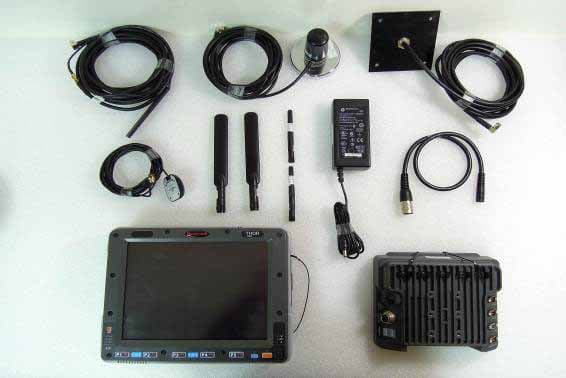
KDZVM2C02
Apr 18, 2013Vehicle Mount Terminal
Equipment Class
DSS - Part 15 Spread Spectrum Transmitter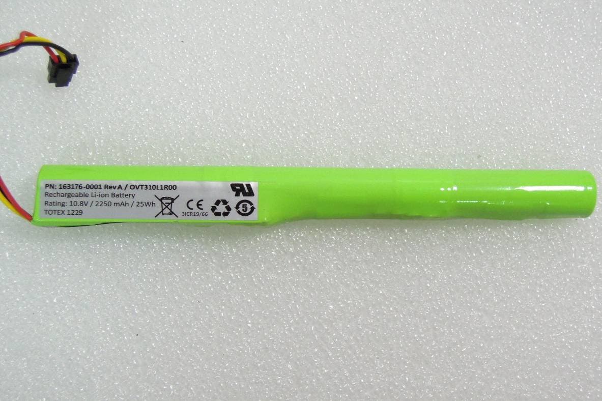
KDZVM2W02
Apr 18, 2013Vehicle Mount Terminal
Equipment Class
PCB - PCS Licensed Transmitter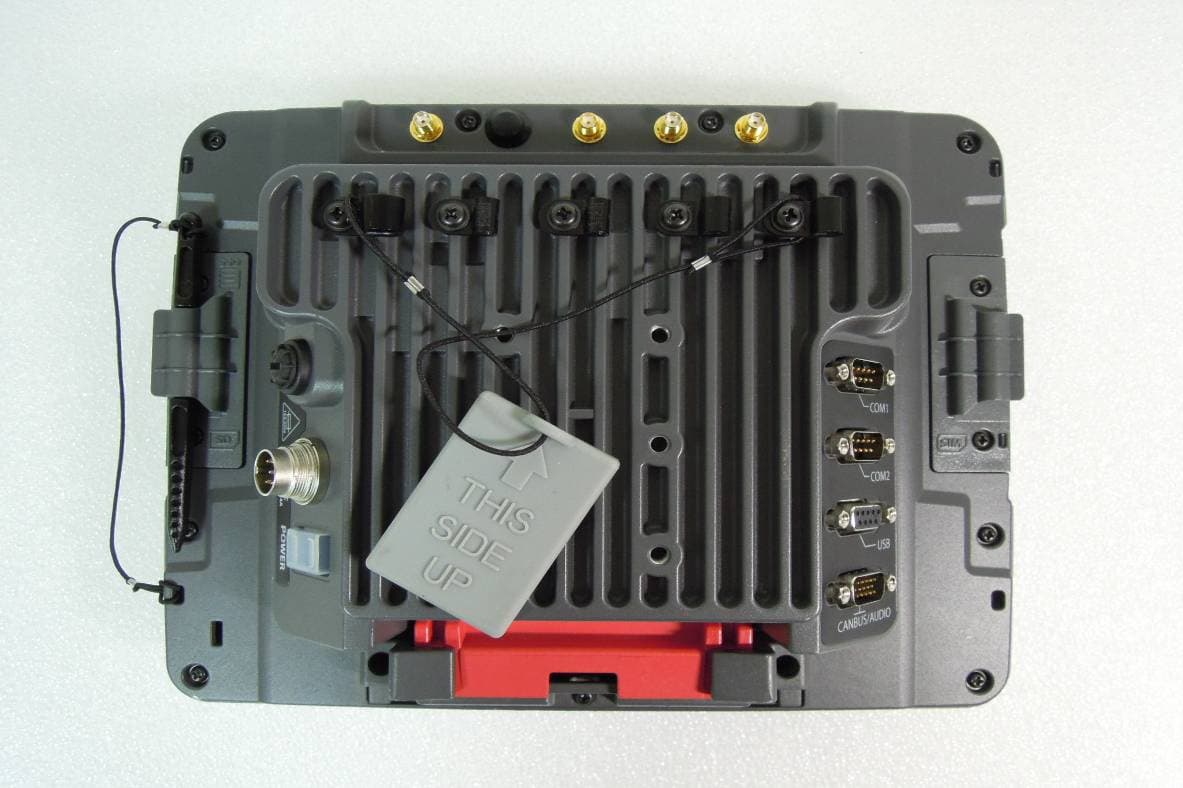
KDZVM2W01
Apr 17, 2013Vehicle Mount Terminal
Equipment Class
DSS - Part 15 Spread Spectrum Transmitter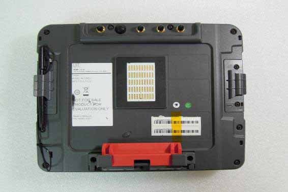
KDZVM2C01
Apr 17, 2013Vehicle Mount Terminal
Equipment Class
DTS - Digital Transmission System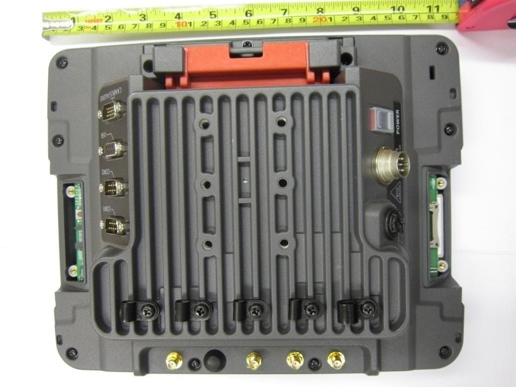
KDZLXE-VM1
Jun 22, 2011Wireless Vehicle Mount Terminal
Equipment Class
DTS - Digital Transmission System