KDZLXERFID2RFID Reader
Honeywell International, Inc.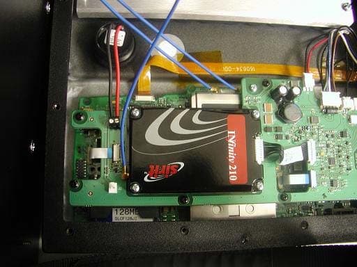
Click to zoom
Application Details
- Equipment Class
- DSS - Part 15 Spread Spectrum Transmitter
- Date of Grant
- Apr 11, 2006
- Application Purpose
- Original Equipment
- Date of Application
- Apr 11, 2006
- Equipment Note
- RFID Reader
- Frequency Range
- 902.75000000 - 927.25000000
- Country
- United States
Documents & Files
Document Text
Text extracted from the exhibit documents filed with the FCC. Open a document above to read the original.
Users Manual
FOR REVIEW ONLY – DO NOT PUBLISH OR DISTRIBUTE DRAFT 08 RX2 User’s Guide (Microsoft ® Windows ® CE .NET Equipped) Copyright © March 2006 by LXE Inc. All Rights Reserved E-EQ-RX2OGWW-A Language: English Notices LXE Inc. reserves the right to make improvements or changes in the products described in this guide at any time without notice. While reasonable efforts have been made in the preparation of this document to assure its accuracy, LXE assumes no liability resulting from any errors or omissions in this document, or from the use of the information contained herein. Further, LXE Incorporated, reserves the right to revise this publication and to make changes to it from time to time without any obligation to notify any person or organization of such revision or changes. Copyright: This manual is copyrighted. All rights are reserved. This document may not, in whole or in part, be copied, photocopied, reproduced, translated or reduced to any electronic medium or machine-readable form without prior consent, in writing, from LXE Inc. Copyright © 2006 by LXE Inc. An EMS Technologies Company. 125 Technology Parkway, Norcross, GA 30092 U.S.A. (770) 447-4224 Trademarks: LXE® is a registered trademark of LXE Inc. Microsoft, Windows and the Windows logo are registered trademarks of Microsoft Corporation in the United States and/or other countries. Java and Java-based trademarks and logos are trademarks or registered trademarks of Sun Microsystems, Inc. in the U.S. or other countries, and are used under license. All other brand or product names are trademarks or registered trademarks of their respective companies or organizations. When this guide is in PDF format: “Acrobat ® Reader Copyright © 1987-2006 Adobe Systems Incorporated. All rights reserved. Adobe, the Adobe logo, Acrobat, and the Acrobat logo are trademarks of Adobe Systems Incorporated.” applies. The user is strongly encouraged to read Appendix A, “Regulatory Notices and Safety Information”. Important safety cautions, warnings and regulatory information is contained in Appendix A. Important: This symbol is placed on the product to remind users to dispose of Waste Electrical and Electronic Equipment (WEEE) appropriately, per Directive 2002-96-EC. In most areas, this product can be recycled, reclaimed and re-used when properly discarded. Do not discard labeled units with trash. For information about proper disposal, contact LXE through your local sales representative, or visit www lxe com. E-EQ-RX2OGWW-A RX2 User’s Guide Table of Contents INTRODUCTION 1 Overview ....................................................................................................................1 Document Conventions ............................................................................................................2 RX2 Environmental Specifications .......................................................................................... 2 Battery Charger Environmental Specifications ........................................................................2 Components ..............................................................................................................3 Quick Start................................................................................................................. 3 RFID Introduction......................................................................................................4 RFID Reader Scan Range .........................................................................................................4 RFID Tag Data Collection........................................................................................................4 Getting Help...............................................................................................................5 Manuals.....................................................................................................................................5 Accessories ...............................................................................................................................5 I NSTALLATION 7 Introduction ...............................................................................................................7 Mounting the RX2 ..................................................................................................... 7 Mounting RX2 Accessories......................................................................................8 Bracket for Coupler (Internal Battery and Charger or External Battery) .................................8 Bracket for Terminal Block (DC to DC Power Supply)...........................................................8 DC to DC Power Supply...........................................................................................................8 Connect Power Source............................................................................................. 9 Internal Battery Pack (Optional)...............................................................................................9 External Battery Pack ............................................................................................................. 10 Vehicle 12VDC Power Connection........................................................................................ 12 DC to DC Power Supply......................................................................................................... 14 The RX2 Battery Charger........................................................................................ 15 O PERATION 17 The Power Switch ...................................................................................................17 The Power LED........................................................................................................ 18 Additional Low Power Warning............................................................................................. 18 Tag Orientation and the RX2.....................................…
Text truncated - open the document above for the full version.
Users Manual
FOR REVIEW ONLY – DO NOT PUBLISH OR DISTRIBUTE DRAFT 08 RX2 User’s Guide (Microsoft ® Windows ® CE .NET Equipped) Copyright © March 2006 by LXE Inc. All Rights Reserved E-EQ-RX2OGWW-A Language: English Notices LXE Inc. reserves the right to make improvements or changes in the products described in this guide at any time without notice. While reasonable efforts have been made in the preparation of this document to assure its accuracy, LXE assumes no liability resulting from any errors or omissions in this document, or from the use of the information contained herein. Further, LXE Incorporated, reserves the right to revise this publication and to make changes to it from time to time without any obligation to notify any person or organization of such revision or changes. Copyright: This manual is copyrighted. All rights are reserved. This document may not, in whole or in part, be copied, photocopied, reproduced, translated or reduced to any electronic medium or machine-readable form without prior consent, in writing, from LXE Inc. Copyright © 2006 by LXE Inc. An EMS Technologies Company. 125 Technology Parkway, Norcross, GA 30092 U.S.A. (770) 447-4224 Trademarks: LXE® is a registered trademark of LXE Inc. Microsoft, Windows and the Windows logo are registered trademarks of Microsoft Corporation in the United States and/or other countries. Java and Java-based trademarks and logos are trademarks or registered trademarks of Sun Microsystems, Inc. in the U.S. or other countries, and are used under license. All other brand or product names are trademarks or registered trademarks of their respective companies or organizations. When this guide is in PDF format: “Acrobat ® Reader Copyright © 1987-2006 Adobe Systems Incorporated. All rights reserved. Adobe, the Adobe logo, Acrobat, and the Acrobat logo are trademarks of Adobe Systems Incorporated.” applies. The user is strongly encouraged to read Appendix A, “Regulatory Notices and Safety Information”. Important safety cautions, warnings and regulatory information is contained in Appendix A. Important: This symbol is placed on the product to remind users to dispose of Waste Electrical and Electronic Equipment (WEEE) appropriately, per Directive 2002-96-EC. In most areas, this product can be recycled, reclaimed and re-used when properly discarded. Do not discard labeled units with trash. For information about proper disposal, contact LXE through your local sales representative, or visit www lxe com. E-EQ-RX2OGWW-A RX2 User’s Guide Table of Contents INTRODUCTION 1 Overview ....................................................................................................................1 Document Conventions ............................................................................................................2 RX2 Environmental Specifications .......................................................................................... 2 Battery Charger Environmental Specifications ........................................................................2 Components ..............................................................................................................3 Quick Start................................................................................................................. 3 RFID Introduction......................................................................................................4 RFID Reader Scan Range .........................................................................................................4 RFID Tag Data Collection........................................................................................................4 Getting Help...............................................................................................................5 Manuals.....................................................................................................................................5 Accessories ...............................................................................................................................5 I NSTALLATION 7 Introduction ...............................................................................................................7 Mounting the RX2 ..................................................................................................... 7 Mounting RX2 Accessories......................................................................................8 Bracket for Coupler (Internal Battery and Charger or External Battery) .................................8 Bracket for Terminal Block (DC to DC Power Supply)...........................................................8 DC to DC Power Supply...........................................................................................................8 Connect Power Source............................................................................................. 9 Internal Battery Pack (Optional)...............................................................................................9 External Battery Pack ............................................................................................................. 10 Vehicle 12VDC Power Connection........................................................................................ 12 DC to DC Power Supply......................................................................................................... 14 The RX2 Battery Charger........................................................................................ 15 O PERATION 17 The Power Switch ...................................................................................................17 The Power LED........................................................................................................ 18 Additional Low Power Warning............................................................................................. 18 Tag Orientation and the RX2.....................................…
Text truncated - open the document above for the full version.
Users Manual
FOR REVIEW ONLY – DO NOT PUBLISH OR DISTRIBUTE DRAFT 08 RX2 User’s Guide (Microsoft ® Windows ® CE .NET Equipped) Copyright © March 2006 by LXE Inc. All Rights Reserved E-EQ-RX2OGWW-A Language: English Notices LXE Inc. reserves the right to make improvements or changes in the products described in this guide at any time without notice. While reasonable efforts have been made in the preparation of this document to assure its accuracy, LXE assumes no liability resulting from any errors or omissions in this document, or from the use of the information contained herein. Further, LXE Incorporated, reserves the right to revise this publication and to make changes to it from time to time without any obligation to notify any person or organization of such revision or changes. Copyright: This manual is copyrighted. All rights are reserved. This document may not, in whole or in part, be copied, photocopied, reproduced, translated or reduced to any electronic medium or machine-readable form without prior consent, in writing, from LXE Inc. Copyright © 2006 by LXE Inc. An EMS Technologies Company. 125 Technology Parkway, Norcross, GA 30092 U.S.A. (770) 447-4224 Trademarks: LXE® is a registered trademark of LXE Inc. Microsoft, Windows and the Windows logo are registered trademarks of Microsoft Corporation in the United States and/or other countries. Java and Java-based trademarks and logos are trademarks or registered trademarks of Sun Microsystems, Inc. in the U.S. or other countries, and are used under license. All other brand or product names are trademarks or registered trademarks of their respective companies or organizations. When this guide is in PDF format: “Acrobat ® Reader Copyright © 1987-2006 Adobe Systems Incorporated. All rights reserved. Adobe, the Adobe logo, Acrobat, and the Acrobat logo are trademarks of Adobe Systems Incorporated.” applies. The user is strongly encouraged to read Appendix A, “Regulatory Notices and Safety Information”. Important safety cautions, warnings and regulatory information is contained in Appendix A. Important: This symbol is placed on the product to remind users to dispose of Waste Electrical and Electronic Equipment (WEEE) appropriately, per Directive 2002-96-EC. In most areas, this product can be recycled, reclaimed and re-used when properly discarded. Do not discard labeled units with trash. For information about proper disposal, contact LXE through your local sales representative, or visit www lxe com. E-EQ-RX2OGWW-A RX2 User’s Guide Table of Contents INTRODUCTION 1 Overview ....................................................................................................................1 Document Conventions ............................................................................................................2 RX2 Environmental Specifications .......................................................................................... 2 Battery Charger Environmental Specifications ........................................................................2 Components ..............................................................................................................3 Quick Start................................................................................................................. 3 RFID Introduction......................................................................................................4 RFID Reader Scan Range .........................................................................................................4 RFID Tag Data Collection........................................................................................................4 Getting Help...............................................................................................................5 Manuals.....................................................................................................................................5 Accessories ...............................................................................................................................5 I NSTALLATION 7 Introduction ...............................................................................................................7 Mounting the RX2 ..................................................................................................... 7 Mounting RX2 Accessories......................................................................................8 Bracket for Coupler (Internal Battery and Charger or External Battery) .................................8 Bracket for Terminal Block (DC to DC Power Supply)...........................................................8 DC to DC Power Supply...........................................................................................................8 Connect Power Source............................................................................................. 9 Internal Battery Pack (Optional)...............................................................................................9 External Battery Pack ............................................................................................................. 10 Vehicle 12VDC Power Connection........................................................................................ 12 DC to DC Power Supply......................................................................................................... 14 The RX2 Battery Charger........................................................................................ 15 O PERATION 17 The Power Switch ...................................................................................................17 The Power LED........................................................................................................ 18 Additional Low Power Warning............................................................................................. 18 Tag Orientation and the RX2.....................................…
Text truncated - open the document above for the full version.
Cover Letter(s)
March 15, 2006 Equipment Autorisation Division Federal Communications Commission 7435 Oakland Mills Road Columbia, MD 21046 FCC ID: KDZLXERFID2 Product Name: RFID READER, LXERFID2 Request for Confidentiality Pursuant to Sections 0.457 and 0.459 of the commissions rules, we hereby request that the following documents be held confidential: • Schematics • Block diagram These materials contain trade secrets and proprietary information and are not customarily released to the public. The public disclosure of this information might be harmful to the company and provide unjustified benefits to our competitors. Dated this 15 th Day of March 20 06 By: Cyril A. Binnom Jr. Signature Printed Title: Approvals Engineer On behalf of : LXE Inc. Telephone: 770-447-4224 x3240
External Photos
125 Technology Parkway Norcross, Georgia, US 30092 March 27, 2006 Test Report LXE Model: RX2 FCC ID: KDZLXERFID2 Mobile Equipment Certification Antenna / RFID Module application photos Internal and External photos Table of Contents Internal Photo – RFID mounting 3 Internal Photo – Antenna Dome attachment 3 Internal Photo – RFID antenna with cable throughput 4 Internal Photo – Cable Attachment throughput 5 External Photo – RX2 in Mounted Position 6 External Photo – Back of Product 7 LXE Model: RX2 LXE Project: 05-083 Internal Photos RFID Module Mounting in RX2 Antenna Dome attachment to Module March 08, 2006 LXE, Inc. Page3 LXE Model: RX2 LXE Project: 05-083 Internal Photos RFID Module with cable throughput attached to Antenna March 08, 2006 LXE, Inc. Page4 LXE Model: RX2 LXE Project: 05-083 Internal Photos Cable attachment throughput to Antenna March 08, 2006 LXE, Inc. Page5 LXE Model: RX2 LXE Project: 05-083 Internal Photos d RX2 in Mounted Position March 08, 2006 LXE, Inc. Page6 LXE Model: RX2 LXE Project: 05-083 Internal Photos Back of Product – Will lay upright on forklift Prepared by: Cyril A. Binnom Jr. Approvals Engineer LXE, Inc. Date: March 27, 2006 March 08, 2006 LXE, Inc. Page7
ID Label/Location Info
125 Technology Parkway Norcross, Georgia, US 30092 March 27, 2006 Test Report LXE Model: RX2 FCC ID: KDZLXERFID2 Mobile Equipment Certification Label & Label Location Table of Contents Labels – FCC ID – Industry Canada – Model Number / FCC and Industry Canada Statements 3 Label Location – FCC ID – Industry Canada – Model Number / FCC and IC Statements 4 LXE Model: RX2 LXE Project: 05-083 Labels and Label Location FCC ID – IC – Model Number FCC Statements March 08, 2006 LXE, Inc. Page3 LXE Model: RX2 LXE Project: 05-083 Labels and Label Location Prepared by: Cyril A. Binnom Jr. Approvals Engineer LXE, Inc. Date: March 27, 2006 March 08, 2006 LXE, Inc. Page4
ID Label/Location Info
125 Technology Parkway Norcross, Georgia, US 30092 March 27, 2006 Test Report LXE Model: RX2 FCC ID: KDZLXERFID2 Mobile Equipment Certification Label & Label Location Table of Contents Labels – FCC ID – Industry Canada – Model Number / FCC and Industry Canada Statements 3 Label Location – FCC ID – Industry Canada – Model Number / FCC and IC Statements 4 LXE Model: RX2 LXE Project: 05-083 Labels and Label Location FCC ID – IC – Model Number FCC Statements March 08, 2006 LXE, Inc. Page3 LXE Model: RX2 LXE Project: 05-083 Labels and Label Location Prepared by: Cyril A. Binnom Jr. Approvals Engineer LXE, Inc. Date: March 27, 2006 March 08, 2006 LXE, Inc. Page4
Internal Photos
Infinity 210 PCB Layout Figure 1 – Bottom of Infinity 210 circuit board Figure 2 – Top of Infinity 210 circuit board Figure 3 – MMCX Antenna Connector
Internal Photos
Infinity 210 PCB Layout Figure 1 – Bottom of Infinity 210 circuit board Figure 2 – Top of Infinity 210 circuit board Figure 3 – MMCX Antenna Connector
Operational Description
Functional Description SIRIT Model INfinity 210 RFID Reader The Sirit INfinity 210 is a RFID reader device that transmits and receives in the 900 MHz ISM band. The RFID tag to be read is energized off this reader via the +30 dBm antenna port RF power radiating out from the patch antenna. The reader sends out an amplitude shift key (ASK) modulated signal to poll the tag. The tag, in turn, generates a frequency shift key (FSK) modulated signal in response. The reader then downconverts and demodulates the received signal and decodes the received tag data. The reader hardware may be functionally divided into two sections: the Transmitter (TX) and the Receiver (RX) sections. Transmitter The TX transmits an ASK modulated signal at a selectable power level between +15 dBm and +30 dBm (maximum power) in 1 dB increments. The frequency of operation is between 902 to 928 MHz and is divided into 50 channels, with the lowest assigned channel at 902.75 MHz and the highest channel at 927.25 MHz. The frequency hopping sequence is pseudo random and is controlled by an on board microprocessor. The microprocessor sends serial data, the clock signal, and enable signal to program the operating channel of the RF synthesizer. The RF synthesizer contains an integrated VCO, and is phase locked to a 20 MHz reference oscillator. This low phase noise VCO is used by both the TX and RX sections. The output of the VCO is fed into a RF buffer amplifier. Since the VCO and buffer amplifier are not signal conditioned, a RF lowpass filter is used in the gain block to remove unwanted harmonics before the signal is split into 2 paths. This filtering will ensure spectral purity for both the RX and TX sections. The lowpass filter is followed by a 2-port 3 dB splitter. One of the splitter ports is routed to the RX section, the other to the TX section. The 3 dB splitter’s TX port output is connected to a RF power amplifier (PA) containing an integrated Analog Power Control (APC) pin.. The power amplifier is matched and optimized to work between 902 and 928 MHz with low harmonic levels. A RF lowpass filter follows the PA and is used to further reduce any harmonic emissions before transmission. The output power level of the power amplifier is controlled by the microprocessor via the APC pin on the power amplifier. The APC pin is also used to ASK modulate the RF carrier signal to send data to the RFID tag. The ASK modulation is shaped to produce a 20 dB occupied bandwidth transmit spectrum of less than 500 kHz. The firmware is also designed to limit the transmitter emission to less than 400 msec on any given channel. The high power RF level is connected to an isolator followed by a directional coupler before it is launched into the patch antenna. Receiver The 3 dB splitter’s RX port output is connected to a 90 degree hybrid and port selection switch before connecting to the downconverting mixer. The RX signal from the patch antenna is routed through a directional coupler and conditioned with a 902-928 MHz bandpass filter before connecting to the mixer where it is down converted, using the same VCO frequency as the transmitter, to a baseband I or Q signal. The I or Q signal is individually selected by the 90 degree hybrid port selector switch. The baseband I or Q signal is then lownoise amplified before connecting to an analog switch that selects between the Class 1 and Class 0 IF processing chains. The Class 1 IF chain consists of a bandpass filter (BW = 280 kHz, corresponding to the received Class 1 tag signal) The Class 0 IF chain consists of a bandpass filter (BW = 480 kHz, corresponding to the received Class 0 tag signal). The output of each IF chain is connected through an analog selector switch to a common limiting IF amplifier that removes amplitude variation from the selected IF signal. The limited FSK IF data is DC level shifted by a data slicer circuit and then sent to the microprocessor for decoding. The received signal strength is also derived from the limiting IF amplifier. Depending on the class of operation, the microprocessor selects the proper IF switch setting to allow the different RFID tag types to be properly filtered before decoding. Block Diagram Frequency Synthesis PLL 902 - 928 MHz VCO SYNTH_SEN SYNTH_SDATA SYNTH_SCLK SYNTH_LOCKED 20 MHz REF_CLK RF Amplifier RX_LO APC PA Final Amplifier Low Pass Filter Isolator Directional Coupler Ant. RF Power Detector FWD PWR 90 Degree Hybrid Low Noise Amplifier RX_LO Band Pass Filter RF Switch Mixer RX IF Low Pass Filter Splitter TX_LO RX_RF 902 - 928 MHz 902 - 928 MHz TX 902 - 928 MHz 902 - 928 MHz 902 - 928 MHz 902 - 928 MHz RX_LO 0 Deg 90 Deg Block Diagram (Cont.) Class 1 Filter RX IF Micro Processor Class 0 Filter Switch Limiter Switch Data Slicer SYNTH_SEN SYNTH_SDATA SYNTH_SCLK SYNTH_LOCKED APC FWD PWR Frequency Hopping Algorithm The INfinity 210 RFID reader polls for tags only under command from the Host computer (external to the RFID reader module), and is inactive otherwise. The Host computer sends requests to the reader for various tag functions, such as reading a tag ID or programming a new ID into a tag. The reader receives the request and carries out the requested function. Each requested function is executed on a new hop channel as shown in the Hop Count column in the table below. The firmware chooses a new Hop Count (or channel) each time a new reader function is issued from the Host. The firmware is also designed to limit the transmitter emission to less than 400 msec on any given channel. The hopping algorithm sequentially increments through the frequency hopping table, with the hop count incremented after each tag function request. The initial starting hop count is randomly determined after INfinity 210 power up, before the first tag function request is processed. The hop count is rolled over to 1 after a count of 50 is reached. The INfinity 210 is not synchronized to other readers and does not have synchronization functionality built in to the reader h…
Text truncated - open the document above for the full version.
Operational Description
Functional Description SIRIT Model INfinity 210 RFID Reader The Sirit INfinity 210 is a RFID reader device that transmits and receives in the 900 MHz ISM band. The RFID tag to be read is energized off this reader via the +30 dBm antenna port RF power radiating out from the patch antenna. The reader sends out an amplitude shift key (ASK) modulated signal to poll the tag. The tag, in turn, generates a frequency shift key (FSK) modulated signal in response. The reader then downconverts and demodulates the received signal and decodes the received tag data. The reader hardware may be functionally divided into two sections: the Transmitter (TX) and the Receiver (RX) sections. Transmitter The TX transmits an ASK modulated signal at a selectable power level between +15 dBm and +30 dBm (maximum power) in 1 dB increments. The frequency of operation is between 902 to 928 MHz and is divided into 50 channels, with the lowest assigned channel at 902.75 MHz and the highest channel at 927.25 MHz. The frequency hopping sequence is pseudo random and is controlled by an on board microprocessor. The microprocessor sends serial data, the clock signal, and enable signal to program the operating channel of the RF synthesizer. The RF synthesizer contains an integrated VCO, and is phase locked to a 20 MHz reference oscillator. This low phase noise VCO is used by both the TX and RX sections. The output of the VCO is fed into a RF buffer amplifier. Since the VCO and buffer amplifier are not signal conditioned, a RF lowpass filter is used in the gain block to remove unwanted harmonics before the signal is split into 2 paths. This filtering will ensure spectral purity for both the RX and TX sections. The lowpass filter is followed by a 2-port 3 dB splitter. One of the splitter ports is routed to the RX section, the other to the TX section. The 3 dB splitter’s TX port output is connected to a RF power amplifier (PA) containing an integrated Analog Power Control (APC) pin.. The power amplifier is matched and optimized to work between 902 and 928 MHz with low harmonic levels. A RF lowpass filter follows the PA and is used to further reduce any harmonic emissions before transmission. The output power level of the power amplifier is controlled by the microprocessor via the APC pin on the power amplifier. The APC pin is also used to ASK modulate the RF carrier signal to send data to the RFI…
Text truncated - open the document above for the full version.
Contact Information
Applicant
Mandana Salahshour(Global Regulatory Compliance Manager)
Technical Contact
Non-Technical Contact
Nemko USAPravin Patel
[email protected]972 436 9600
Test Firm
Nemko USA, Inc.Tom Tidwell
Technical Specifications
| # | Rule Parts | Frequency Range | Power Output |
|---|---|---|---|
| 1 | 15C | 902.75 MHz - 927.25 MHz | 944.00 mW |
Other Applications from Honeywell International, Inc.
KDZVM2C02
Apr 18, 2013Vehicle Mount Terminal
Equipment Class
DSS - Part 15 Spread Spectrum Transmitter
KDZVM2W02
Apr 18, 2013Vehicle Mount Terminal
Equipment Class
PCB - PCS Licensed Transmitter
KDZVM2W01
Apr 17, 2013Vehicle Mount Terminal
Equipment Class
DSS - Part 15 Spread Spectrum Transmitter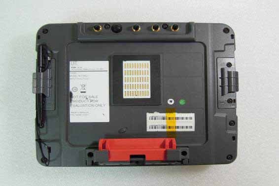
KDZVM2C01
Apr 17, 2013Vehicle Mount Terminal
Equipment Class
DTS - Digital Transmission System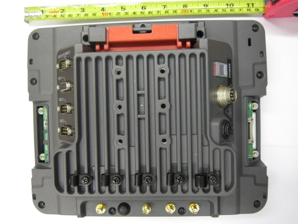
KDZLXE-VM1
Jun 22, 2011Wireless Vehicle Mount Terminal
Equipment Class
DTS - Digital Transmission System