KH5MED99038801Microwave Electronic Dog
Microtek Lab Inc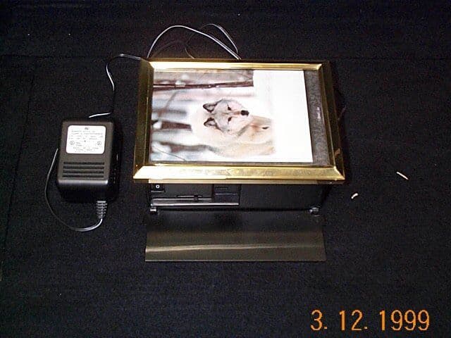
Click to zoom
Application Details
- Equipment Class
- DSR - Part 15 Remote Control/Security Device Transceiver
- Date of Grant
- Apr 18, 1999
- Application Purpose
- Original Equipment
- Date of Application
- Mar 16, 1999
- Equipment Note
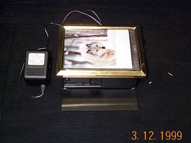
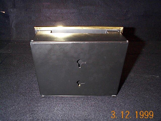
- Microwave Electronic Dog
- Frequency Range
- 5725.00000000 - 5850.00000000
- Company
- Microtek Lab Inc
- Country
- United States
Documents & Files
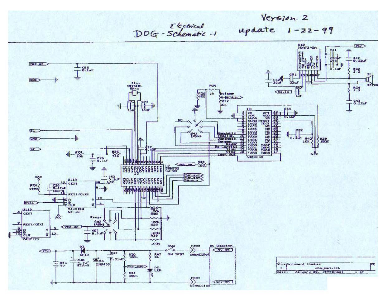
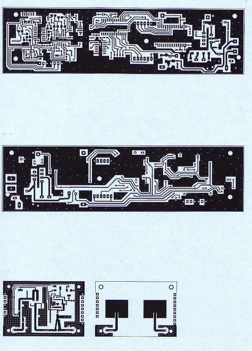
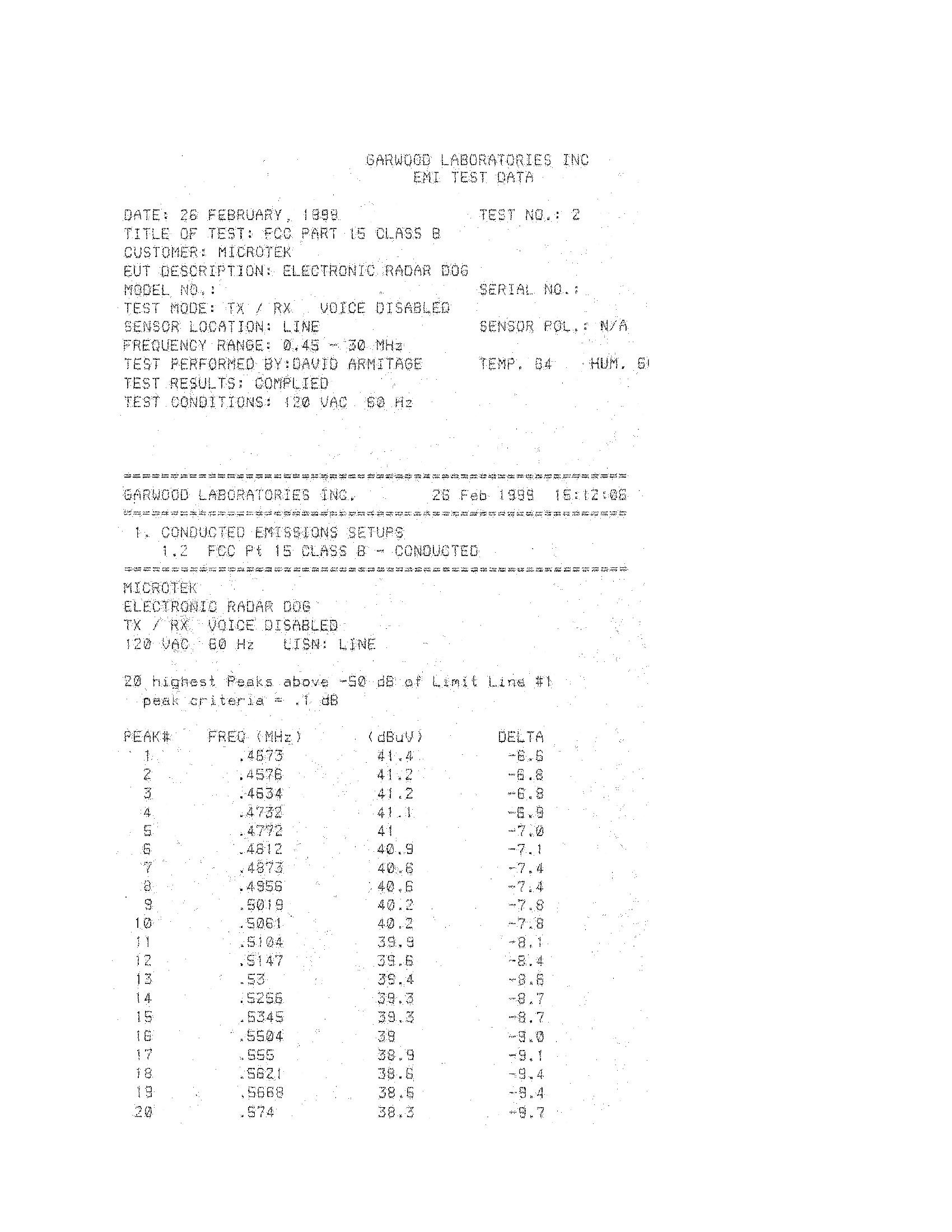
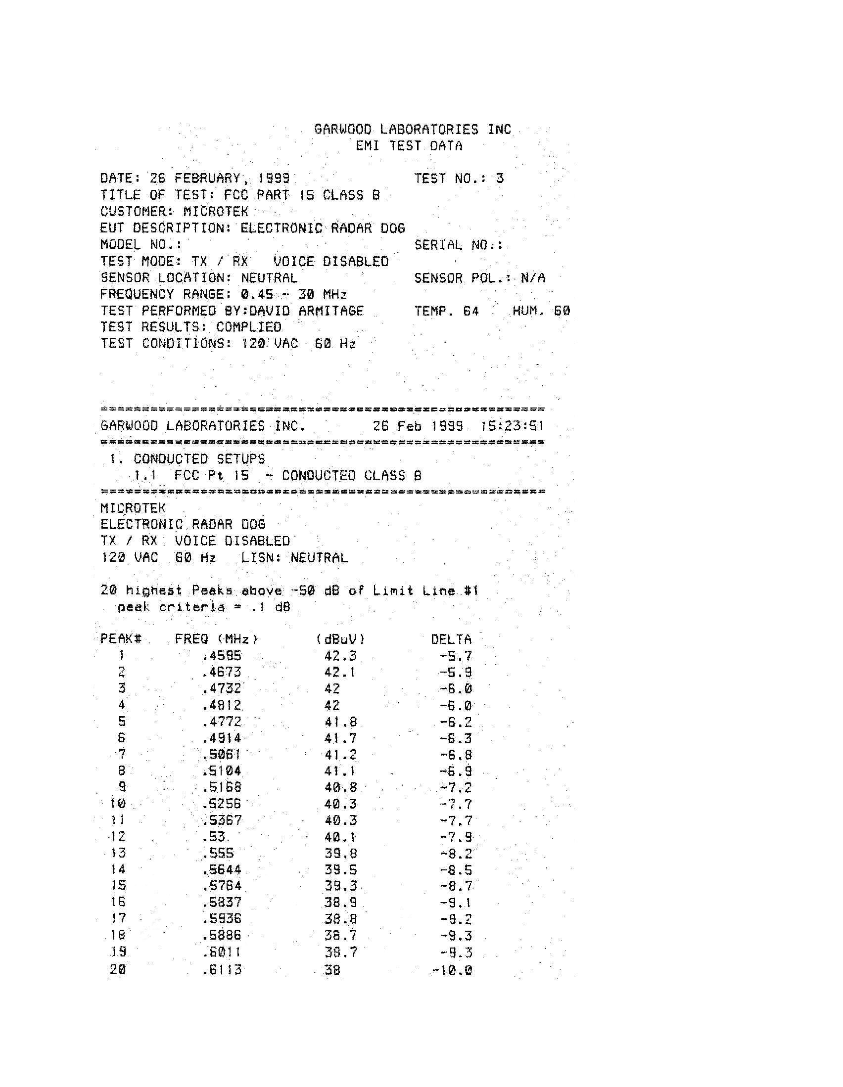
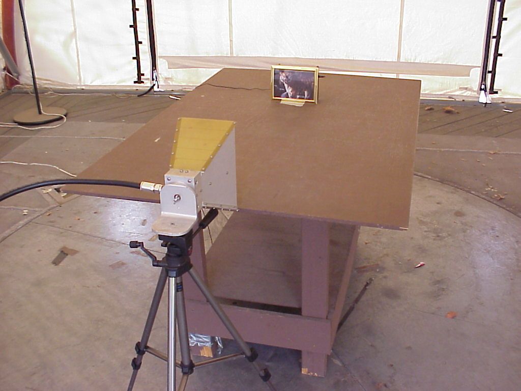
Document Text
Text extracted from the exhibit documents filed with the FCC. Open a document above to read the original.
Users Manual
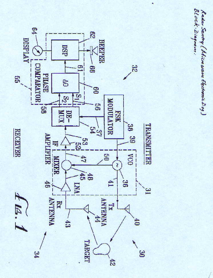
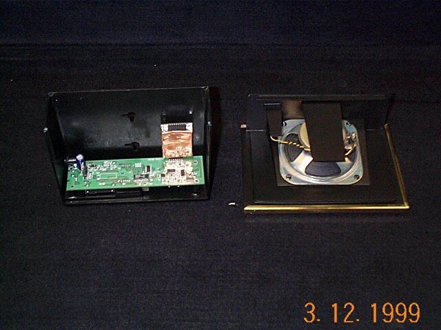
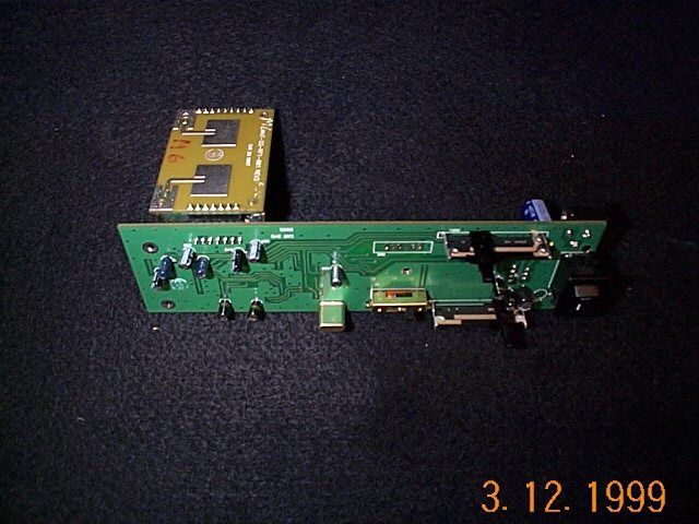
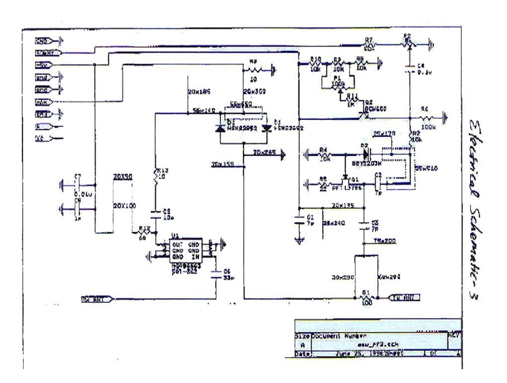
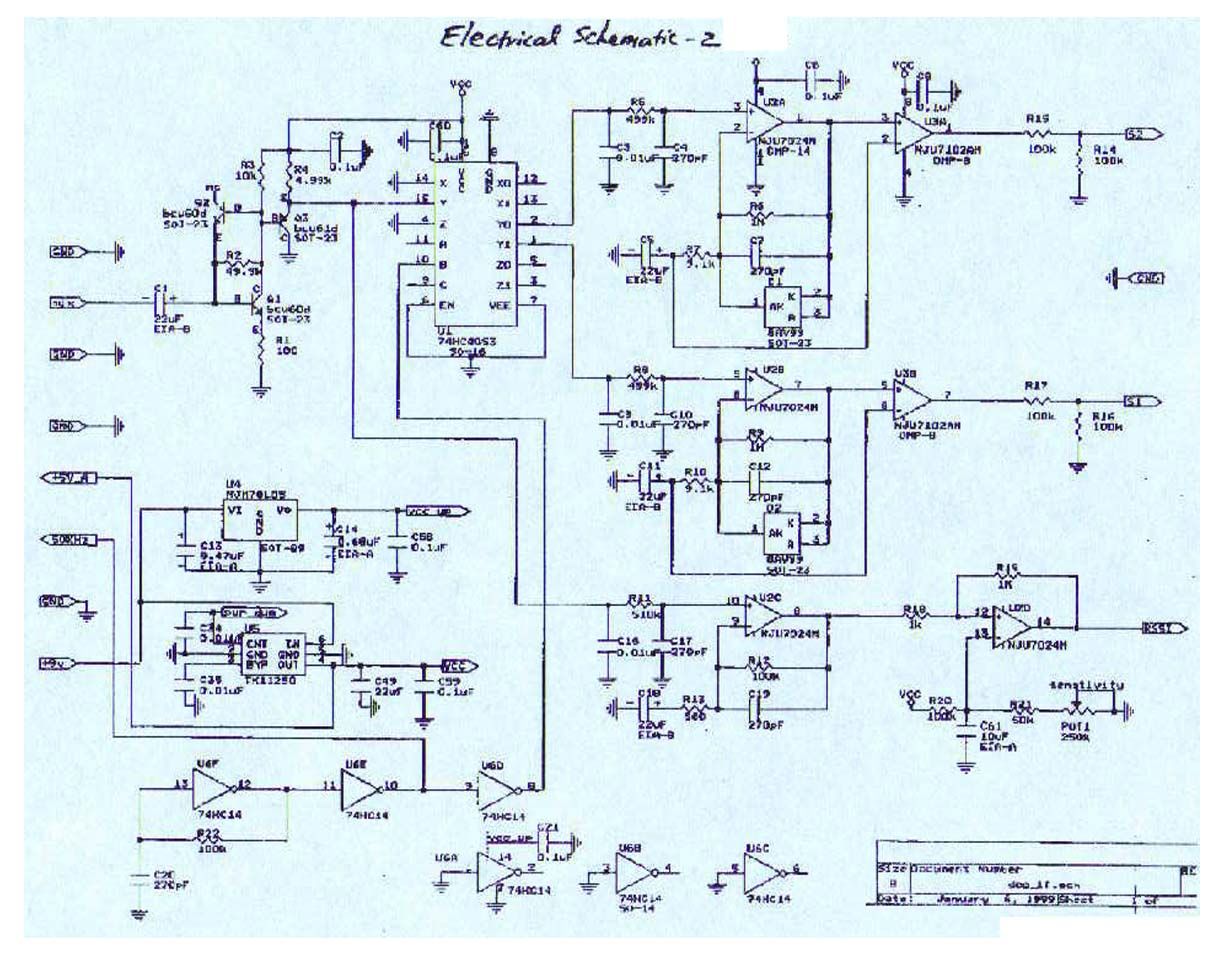
Radar Sentry (Microwave Electronic Dog) Manual Introduction Thank you for purchasing the Microtek Radar Sentry (Microwave Electronic Dog). The device is designed to provide maximum safety to your family and home by providing immediate warnings of an incoming intruder. By incorporating radar technology, the electronic dog can detect moving objects through various materials such as concrete and plaster walls, wooden structures, and window glass. A number of sound effects can be selected to alert you when an intruder approaches. As the intruder moves closer, the intensity of the sound effect responses with greater urgency -- the barks become growls, and the alarm beeps louder and faster. Adjustable volume and range of detection control enables you to select the appropriate level of settings necessary for your application. The electronic dog provides reliable security day and night whether you are away from home or at home asleep in bed. This versatile unit allows you to utilize it anywhere you please -- homes, apartments, dorm rooms, offices, garages, storage spaces, tents, cabins, trucks, containers, RVs, boats, etc. Operating the Unit Select a desirable position* for your unit. Make sure the selected position is close to an AC outlet. Insert the female head of the AC adaptor into the male slot labeled DC IN 12V on the back of the unit. Then plug the AC adaptor into the electrical outlet. NOTE: Please use only the supplied AC adaptor included in this product. *: Desirable positions: e.g. window sills of living room, family room, bed room, and kitchen; end tables near front window and main door; and the wall next to main gate and garage door. Turning on the Unit Open the unit cover and turn on the power. Choosing a Sound Effect Switch Select a sound effect by sliding the sound select switch to the following sound functions: 1) Westminster bell with a “Welcome”. A. For distance less than 3 feet, it will generate a voice “Welcome”. B. For distance between 4 to 6 feet, it will generate Westminster bell part II. C. For distance longer than 7 feet, it will generate Westminster bell part I. 2) Dog barking sound follows with Siren. A. Multiple dog barking with siren for distance less than 3 feet. B. Two dog barking for distance between 4 to 6 feet. C. Single dog barking for distance longer than 7 feet. 3) Dog barking sound without Siren. The function is the same as the 2), except no siren for distance less than 3 feet. 4) Beeping A. Intense high frequency high beeping sound for distance less than 3 feet. B. Moderate beeping sound for distance between 4 to 6 feet. C. Low beeping for distance longer than 7 feet. Detection Range The detection range can be adjusted using the range knob. There are four range selects available: 1) distance less than 3 feet, 2) distance less than 6 feet , 3) distance less than 9 feet, and 4) distance farther than 10 feet. The types of barking and beeping sound at different ranges can be selected. At maximum range sensitivity, the Radar Sentry will detect movement up to 20 feet away. Sensitivity Control Turn the sensitivity slide to adjust the desired sensitivity level. Volume Control Turn the volume slide to adjust the desired volume level. Placement Position the radar in the area you wish to detect motion. Radar technology allows the unit to have 1) a detection angle of 110° and 2) an ability to detect movement through a variety of non-metalic materials. Place the unit 3 to 5 feet above the floor with the unit facing towards the assigned area. Characteristics • Detect motion using advanced microwave detector technology. • Penetrate window glass, doors, and walls. • Adjustable volume control and detection range settings. • Different sounds of warning signal depending on distance. • The closer the intruder, the higher the beeping frequency of the warning signals. • 5.8 GHz double pulse-frequency Doppler measurement. • Operating distance up to 20 feet with 110° monitoring angles. • Portable and versatile to be placed in any location. • Temper proof, monitor outdoor motion with indoor devices. • Specifications • Power Supply: AC adaptor with 1 Amp and DC 12V. • Operating Temperature: - 20° to + 65°C • Detection: Microwave transmitter/receiver sensor • Design: Microwave sensing with various frequency warning signals. • Weight: 1.5 lb.s Applications • Intruder alert and warning. • Apply wherever extra security is needed. • Guard homes, offices, apartments, dormitory, RVs, boats, camping ground, etc. • Deter any possible intrusion by strangers. Benefits • Provide peace of mind for home owners and family. • Warns family and homeowner of possible intrusion. • Safeguard valuables, irreplaceable jewelry, and documents. • Extra security when stationing in a new unfamiliar place during traveling or camping. • Reduce the risk of potential harm and damage caused by an intruder.
Cover Letter(s)
March 25, 1999 To Whom It May Concern: Federal Communications Commission 7435 Oakland Mills Road Columbia, Maryland 21046 Subject: FCC Test Report Revision Dear Reviewer, The first test report submitted on 03/23/99 has been revised and updated. Please refer to test report sent to you on 03/25/99. The first test report reflect an error on our part. We initially declared to Section 245 instead of 249. Sorry for the misunderstanding and any inconveniences. We look forward to getting the product approved in a timely manner. Please do not hesitate to give me a call at (714) 688-2590 if you have any questions or comments. Cordially, Thomas K. Ha Thomas K. Ha G&M Compliance
ID Label/Location Info
Microtek Wireless Design Model No.: MED-001 FCCID No.: KH5MED99038801 This device complies with the FCC Part 15 rules. Operation of the device is subject to the following conditions: 1) this device may not cause harmful interference, and 2) this device must accept any interference received, including interference that may cause undesired operation. International Patent Application No.: PCT/US98/07710 The label will be placed on the bottom of the unit.
Test Report
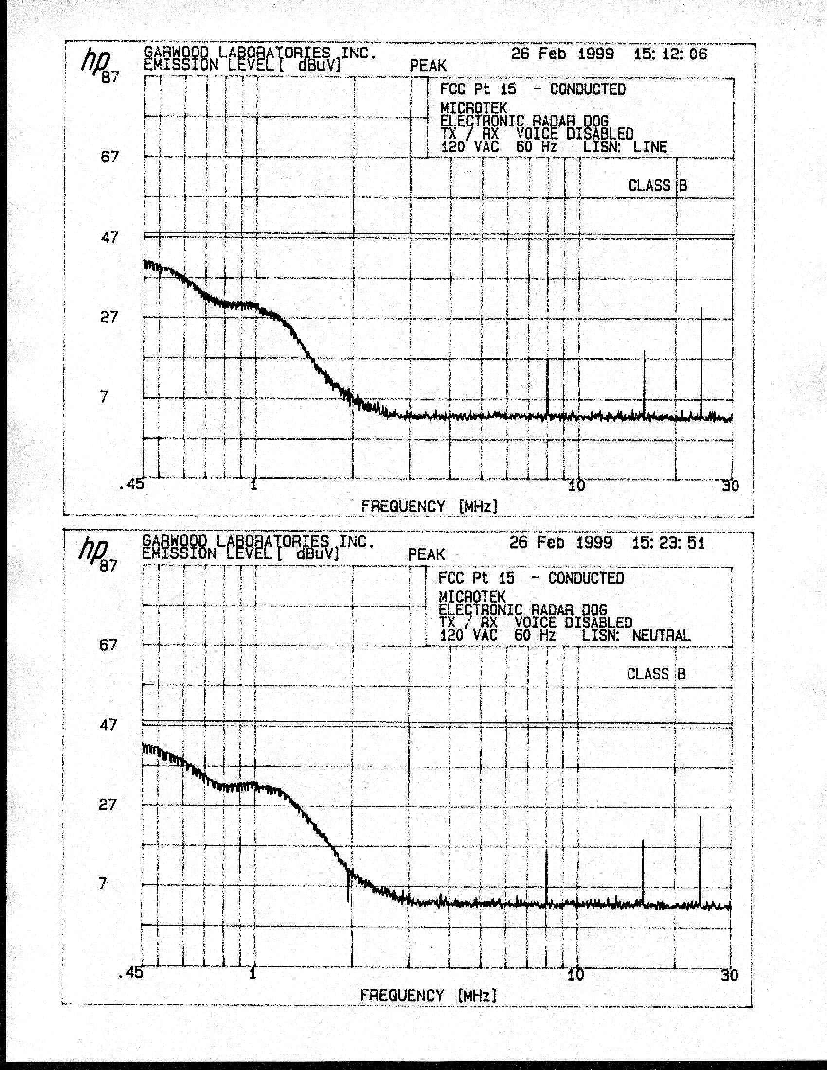
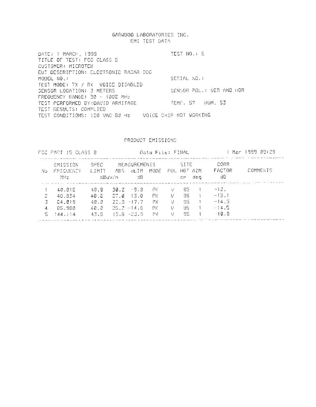
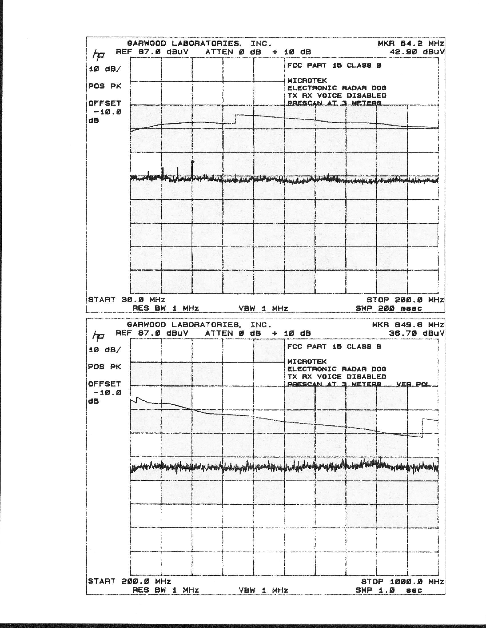
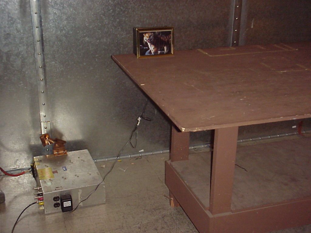
FCC CERTIFICATION TEST REPORT COMPANY:MICROTEK Lab, Inc. PRODUCT(S):Microwave Electronic Dog Model MED-001 REPORT No:MLI-002 APPROVED BY:Edward Nakauchi Edward M. Nakauchi, E.M.C. Manager PREPARED BY:Thomas K. Ha Thomas K. Ha, Report Writer DATE:March 15, 1999 TOTAL PAGES: 17 All services undertaken are subject to the following general policy: Reports are submitted for exclusive use of the client to whom they are addressed. Their significance is subject to the adequacy and representative character of the samples and to the comprehensiveness of the tests, examinations or surveys made. G & M COMPLIANCE Report No: MLI-0022 of 17 CONTENTS 1.0 PROJECT DESCRIPTION.........................................................................3 2.0TEST SUMMARY........................................................................................4 3.0PRODUCT DESCRIPTION........................................................................5 4.0TEST PROCEDURES..................................................................................6 5.0 TEST RESULTS..........................................................................................7 6.0TEST EQUIPMENT....................................................................................11 7.0TEST DATA PRINTOUTS.........................................................................12 8.0USER’S MANUAL................................................................................14 9.0BLOCK DIAGRAM/SCHEMATICS........................................................15 10.0PHOTOGRAPHS OF TEST SETUPS.......................................................16 11.0PHOTOGRAPHS OF EUT.........................................................................17 1.0PROJECT DESCRIPTION G & M COMPLIANCE Report No: MLI-002 3 of 17 Equipment:Microwave Electronic Dog Model:Model MED-001 Equipment Serial No:N/A Voltage/Phase:115VAC / 60 Hz Client:MICROTEK Lab, Inc. 3715 Doolittle Drive Redondo Beach, CA 90278 Test Standard(s):CFR No. 47 - October 1997. FCC Part 15 Subpart C. FIELD DISTURBANCE SENSOR Date Sample Submitted:February 25, 1999 Test Work Started:February 26, 1999 Test Work Completed:March 01, 1999 2.0TEST SUMMARY G & M COMPLIANCE Report No: MLI-002 4 of 17 When configured and operated as specified in this report, the product was tested to the requirements as indicated below. Test StandardTest Comment FCC Part 15 Subpart C Section 15.207Conducted EmissionsPASS Section 15.209Radiated EmissionsPASS Section 15.245Field Disturbance Sensor (5785 - 5815 MHz)PASS G & M COMPLIANCE Report No: MLI-002 5 of 17 3.0 PRODUCT DESCRIPTION The EUT is a Microwave Electronic Dog. It is a radar sentry system designed to provide immediate warnings of an incoming intruder for security applications. By incorporating microwave detection technology, the electronic dog can detect moving objects through various materials such as concrete, plaster walls, wooden structures and windows. A number of sound effects can be selected to alert the user of an intruder. It operates at around 5.8 GHz incorporating double pulses doppler measurement. The EUT is effective up to 15 ft of monitoring distance at 110 degrees angle. The EUT incorporates a 120 VAC plugging power supply, 1.0 Amp, 60 Hz. The output of the supply (12 VDC) essentially powers the EUT. 3.1TEST CONFIGURATION Refer to Section 10.0 for test setups. The product was powered with a 120VAC / 60 Hz supply. 3.2SUPPORT EQUIPMENT/SERVICES N/A 3.3MODE OF OPERATION The EUT was operating as intended under normal condition. G & M COMPLIANCE Report No: MLI-002 6 of 17 4.0TEST PROCEDURES 4.1Conducted Emissions The test was performed in accordance with ANSI C63.4. Table top products are placed on a non conducting table 0.8 m above a 5.8 x 6.4 m steel ground reference plane and 0.4 m from a 3.6 m x 3 m vertical ground reference plane. Floor mounted products are placed on a 0.1 m isolating platform in the center of the 5.8 x 6.4 m steel reference plane. For single phase products with current consumption of less than 25 amps, conducted emissions are measured via a line impedance stabilization network. For other products a voltage probe is used. Initially a scan was made with an EMI receiver from 450 kHz to 30 MHz on each phase with the receiver in peak mode. The receiver IF bandwidth was 9 kHz and scan step size was 5 kHz. Measurements were then made using CISPR quasi peak and average detectors when the peak readings were within 10 dB of the lower average limit line. 4.2Radiated Emissions Testing was performed in accordance with ANSI C63.4. Initially the product was placed in a 7 m x 3.7 m x 3.0 m anechoic chamber and a prescan was performed with the antenna at a 3 meters measurement distance. The scan was made with the receiver in peak mode, the IF bandwidth was 120 kHz and the step size was 50 KHz. Final measurements will be performed on a 10 m open area test site which meets the site attenuation requirements of CISPR 16. The site consists of an 18 m x 4.8 m 16 gage galvanized steel ground plane with a flush mounted 2.3 m diameter turntable at one end. The site is free from reflecting objects over an elliptical area of 20 m x 17.4 m as required by the standard. The maximum peak readings determined from the prescan were then investigated on the open area test site. At each frequency the turntable was rotated through 360 degrees, the height of the antenna was adjusted between 1 and 4 meters and the polarization was adjusted between vertical and horizontal to determine the maximum Quasi Peak reading. G & M COMPLIANCE Report No: MLI-002 7 of 17 5.0TEST RESULTS 5.1 Emissions Results Standard: FCC Part 15 Subpart C, Section 15.207 Test: Conducted Emissions Frequency Range: 450 KHz to 30 MHz Limits: Class B Line conductor Data below shows the results of peak measurements on the AC line conductor of the EUT. The measurements were made and the 10 highest peak readings are shown below: FrequencyLevelLimitPASS/FAIL MHz (dBμ μμ μV)(dBμ μμ μV) 0.46741.…
Text truncated - open the document above for the full version.
Test Report
FCC CERTIFICATION TEST REPORT COMPANY:MICROTEK Lab, Inc. PRODUCT(S):Microwave Electronic Dog Model MED-001 REPORT No:MLI-002 APPROVED BY:Edward Nakauchi Edward M. Nakauchi, E.M.C. Manager PREPARED BY:Thomas K. Ha Thomas K. Ha, Report Writer DATE:March 15, 1999 TOTAL PAGES: 17 All services undertaken are subject to the following general policy: Reports are submitted for exclusive use of the client to whom they are addressed. Their significance is subject to the adequacy and representative character of the samples and to the comprehensiveness of the tests, examinations or surveys made. G & M COMPLIANCE Report No: MLI-0022 of 17 CONTENTS 1.0 PROJECT DESCRIPTION.........................................................................3 2.0TEST SUMMARY........................................................................................4 3.0PRODUCT DESCRIPTION........................................................................5 4.0TEST PROCEDURES..................................................................................6 5.0 TEST RESULTS..........................................................................................7 6.0TEST EQUIPMENT....................................................................................11 7.0TEST DATA PRINTOUTS.........................................................................12 8.0USER’S MANUAL................................................................................14 9.0BLOCK DIAGRAM/SCHEMATICS........................................................15 10.0PHOTOGRAPHS OF TEST SETUPS.......................................................16 11.0PHOTOGRAPHS OF EUT.........................................................................17 1.0PROJECT DESCRIPTION G & M COMPLIANCE Report No: MLI-002 3 of 17 Equipment:Microwave Electronic Dog Model:Model MED-001 Equipment Serial No:N/A Voltage/Phase:115VAC / 60 Hz Client:MICROTEK Lab, Inc. 3715 Doolittle Drive Redondo Beach, CA 90278 Test Standard(s):CFR No. 47 - October 1997. FCC Part 15 Subpart C. INTENTIONAL RADIATOR Date Sample Submitted:February 25, 1999 Test Work Started:February 26, 1999 Test Work Completed:March 01, 1999 2.0TEST SUMMARY G & M COMPLIANCE Report No: MLI-002 4 of 17 When configured and operated as specified in this report, the product was tested to the requirements as indicated below. Test StandardTest Comment FCC Part 15 Subpart C Section 15.207Conducted EmissionsPASS Section 15.209Radiated EmissionsPASS Section 15.249Intentional Radiator (5725 - 5875 MHz)PASS G & M COMPLIANCE Report No: MLI-002 5 of 17 3.0 PRODUCT DESCRIPTION The EUT is a Microwave Electronic Dog. It is a radar sentry system designed to provide immediate warnings of an incoming intruder for security applications. By incorporating microwave detection technology, the electronic dog can detect moving objects through various materials such as concrete, plaster walls, wooden structures and windows. A number of sound effects can be selected to alert the user of an intruder. It operates at around 5.8 GHz incorporating double pulses doppler measurement. The EUT is effective up to 15 ft of monitoring distance at 110 degrees angle. The EUT incorporates a 120 VAC plugging power supply, 1.0 Amp, 60 Hz. The output of the supply (12 VDC) essentially powers the EUT. 3.1TEST CONFIGURATION Refer to Section 10.0 for test setups. The product was powered with a 120VAC / 60 Hz supply. 3.2SUPPORT EQUIPMENT/SERVICES N/A 3.3MODE OF OPERATION The EUT was operating as intended under normal condition. G & M COMPLIANCE Report No: MLI-002 6 of 17 4.0TEST PROCEDURES 4.1Conducted Emissions The test was performed in accordance with ANSI C63.4. Table top products are placed on a non conducting table 0.8 m above a 5.8 x 6.4 m steel ground reference plane and 0.4 m from a 3.6 m x 3 m vertical ground reference plane. Floor mounted products are placed on a 0.1 m isolating platform in the center of the 5.8 x 6.4 m steel reference plane. For single phase products with current consumption of less than 25 amps, conducted emissions are measured via a line impedance stabilization network. For other products a voltage probe is used. Initially a scan was made with an EMI receiver from 450 kHz to 30 MHz on each phase with the receiver in peak mode. The receiver IF bandwidth was 9 kHz and scan step size was 5 kHz. Measurements were then made using CISPR quasi peak and average detectors when the peak readings were within 10 dB of the lower average limit line. 4.2Radiated Emissions Testing was performed in accordance with ANSI C63.4. Initially the product was placed in a 7 m x 3.7 m x 3.0 m anechoic chamber and a prescan was performed with the antenna at a 3 meters measurement distance. The scan was made with the receiver in peak mode, the IF bandwidth was 120 kHz and the step size was 50 KHz. Final measurements will be performed on a 10 m open area test site which meets the site attenuation requirements of CISPR 16. The site consists of an 18 m x 4.8 m 16 gage galvanized steel ground plane with a flush mounted 2.3 m diameter turntable at one end. The site is free from reflecting objects over an elliptical area of 20 m x 17.4 m as required by the standard. The maximum peak readings determined from the prescan were then investigated on the open area test site. At each frequency the turntable was rotated through 360 degrees, the height of the antenna was adjusted between 1 and 4 meters and the polarization was adjusted between vertical and horizontal to determine the maximum Quasi Peak reading. G & M COMPLIANCE Report No: MLI-002 7 of 17 5.0TEST RESULTS 5.1 Emissions Results Standard: FCC Part 15 Subpart C, Section 15.207 Test: Conducted Emissions Frequency Range: 450 KHz to 30 MHz Limits: Class B Line conductor Data below shows the results of peak measurements on the AC line conductor of the EUT. The measurements were made and the 10 highest peak readings are shown below: FrequencyLevelLimitPASS/FAIL MHz (dBμ μμ μV)(dBμ μμ μV) 0.46741.448.0PAS…
Text truncated - open the document above for the full version.
Contact Information
Applicant
C Stewart Chow
310-297-5000
Technical Contact
G&M ComplianceThomas K Ha
[email protected]714-688-2590
3900 East Miraloma, #C · Anaheim, California · United States
Test Firm
Garwood Laboratories, Inc.Jason Armstrong
714-572-2027Fax: 714-572-2025
Technical Specifications
| # | Rule Parts | Frequency Range | Power Output |
|---|---|---|---|
| 1 | 15C | 5.72 GHz - 5.85 GHz | 1.00 mW |
Other Applications from Microtek Lab Inc
KH5MED99108802
Jan 12, 2000Personal Sentry
Equipment Class
DXX - Part 15 Low Power Communication Device Transmitter