KH8-RFD1R/C Transmitter
FMA Inc
Click to zoom
Application Details
- Equipment Class
- TNB - Licensed Non-Broadcast Station Transmitter
- Date of Grant
- Jul 09, 2001
- Application Purpose
- Original Equipment
- Date of Application
- Jul 09, 2001
- Equipment Note
- R/C Transmitter
- Frequency Range
- 72.01000000 - 75.99000000
- Company
- FMA Inc
- Country
- United States
Documents & Files
Document Text
Text extracted from the exhibit documents filed with the FCC. Open a document above to read the original.
Users Manual
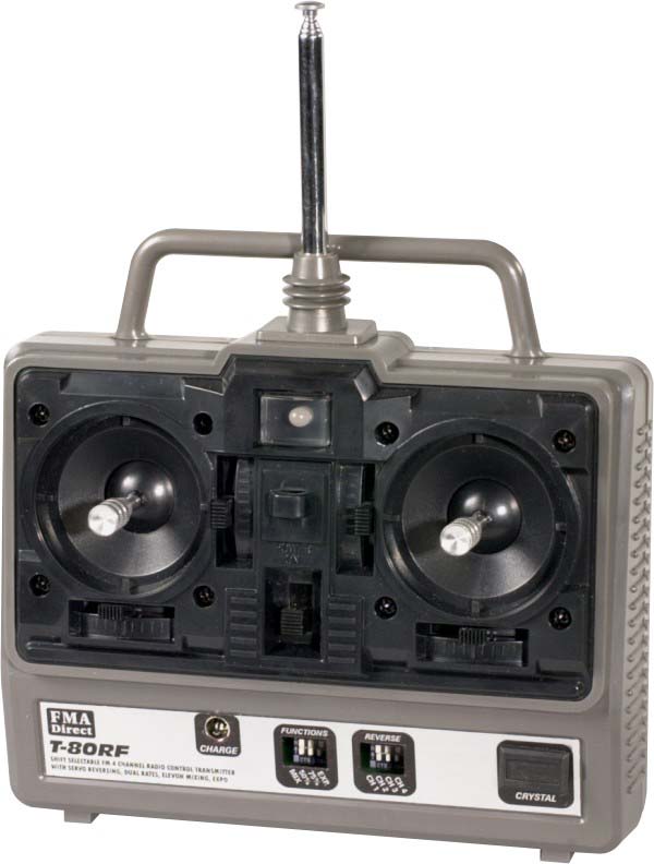
T80RF 4 Channel, microcomputer FM R/C Transmitter OPERATIONS MANUAL NOTE: PLEASE READ MANUAL COMPLETELY BEFORE OPERATION FMA, Inc. 9607 Dr. Perry Road - Unit 109 Ijamsville, MD 21754 Sales: (800) 343-2934 -Technical: (301) 831-8980 RF FRQUENCY SELECTION You may operate your T80 transmitter on any one of fifty RF channels at 72 MHz for airborne models and on any one of 30 RF channels at 75MHz by selection of frequency at purchase. By F.C.C. regulations, you are not permitted to change the frequency determining element (Crystal) in your transmitter unless you are a valid holder of an F.C.C. Second Class Operator's License. 4 OR 5 CHANNEL OPERATION No matter how complex your model, T80 has the channel flexibility and capacity to allow you to operate any model you can build requiring from one to five independent channels of control. If your transmitter has five channel capability, that option may be by either a switch for retract gear or by a control knob provided for remote control of the sensitivity of the FMA COPILOT Dave(tm). MIXING The T80 has a program selection for mixing of aileron and elevator as used for elevons or V-tail controls. SERVO REVERSING ON 4 CHANNELS One can electronically change the direction of any servo using the control panel on the front of T80. A very important result obtains: Install the servos in the most direct and functional way, to put the emphasis on the control linkage quality and reverse the servo's direction as necessary. TRI-RATES FOR AILERON, ELEVATOR, AND RUDDER Tri-rates gives the ability to desensitize the controls of the trainer aircraft while learning to fly without making permanent changes in linkages or available servo travel. TX BATTERY EVALUATION SYSTEM Transmitter battery voltage is displayed at all times during operation. The tri-color LED display located at the upper edge of the face of the transmitter glows green for normal operating range, transitions to yellow when the battery approaches 9V, and turns red when the danger zone is reached. If you ever observe the display turning red, land or return your model to your presence as soon as possible. Please do check the warning light from time to time, not after your model has crashed! Thank you for choosing the FMA Direct T80RF, 4 channel, FM radio control transmitter. FMA Direct has been designing radio control equipment for modelers for over 30 years. The " T80RF" uses an advanced microprocessor to control every function of the radio including: • Rates (50%, 75%, 100%) • Mi xing (Elevon/Vtail Mi x) • Servo Reversing (All 4 Channels) • Frequency shift selection (Posi ti ve or Negati ve) The main purpose of the T80RF radio is to provide a flexible and reliable radio control system that will take the modeler into the 21st Century. The "T80RF" meets all spectrum occupancy regulations imposed by the F.C.C.. The use of the Master Oscillator, Power Amplifier system of generating RF allows for super narrow band, clean transmission. This permi ts virtually all the transmitted RF to be at the frequency of the interest instead of having inefficient dissipation of power in unwanted har monics. Careful shaping of the modulation pulses by a Miller Integrator ensures efficient use for the occupied spectrum. Please read this manual carefully before using your T80RF. Let us know how the system works for you! INTRODUCTION & FEA TURES S P E C IF IC A T IO N S SIZE: 6.75”L X 2.60”D (INCLUDI NG STICKS) X 6.25”H (INCLUDING HANDLE) WEIGHT: 4 oz. (W/OUT BATTERIES) FUNCTI ON: 4 CHANNEL, COMPUTER CONTROLLED, FM R/C SYSTEM RF OUTP UT P OW ER: 400 Mw FREQUENCIES: ALL LEGAL 72 MHz AND 75 MHz R/C FREQUENCIES CH 11– CH 90 MODULATI ON: FM/PPM (UNIVERSAL, SELECTABLE SHIFT + OR -) POWER SYSTEM: 8 “AA” ALKALINE OR OPTI ONAL ONE 8 CELL, NICD (600 Mah) CURRENT DRAI N: 150 mA OPERATING PULSE WIDTH 1.0ms TO 2.0ms EACH CHANNEL (1.5ms NEUTRAL) FEA TURES ERGONOMICALLY DESIGNED CASE The case of the T80 has been designed to give the maximum grip on the box while allowing your fingers freedom and flexibility to control your model smoothly and safely. TRIMS Each of the four (stick controlled) channels has a trimming adjustment alongside the appropriate direction of motion. These trims give 15 degrees of control authority in each direction to compensate for inaccuracies in the model or local conditions. They shift the entire range of the channel motion. It is advisable to re-center the trims after each use and make the appropriate modifications to the control surfacs using the adjustable push-rod clevis. This way the servos are centered instead of being biased off-center. It is important to know that having servos off- center will cause non-linearity of control motion and should be avoided. SETTING UP Plug in the servos, receiver, battery, and switch harness that you plan to use. Check that the switches for the mixing circuits are in the OFF position before turning on the radio. Turn on the transmitter and then the receiver. The LED battery condition display should illuminate and be green. Please be aware that the transmitter will be radiating when you turn on. If you are operating you model at a club facility, be sure to observe the frequency control system in effect at that location and to comply with local procedures for operating your transmitter. STICK MODE The stick mode can be changed from 1 to 2 as described below. The stick mode is purely a preferential choice with Mode 2 being the m9ost common choice in the U.S. Basically, the throttle stick in the U.S. in Mode 2 is on the left and in Mode 1, it's on the right. All compensation is automatically handled by swapping the elevator and throttle connector cables at the encoder board and the spring for the elevator need be moved to the opposite stick by removing the back and physically changing the spring and ratchet exactly as they were on the opposite side. MODULATION/FREQUENCY SHIFT PPM is the baseline mode for T80. PPM allows for the use of the radio with FM receivers you may own. …
Text truncated - open the document above for the full version.
Operational Description
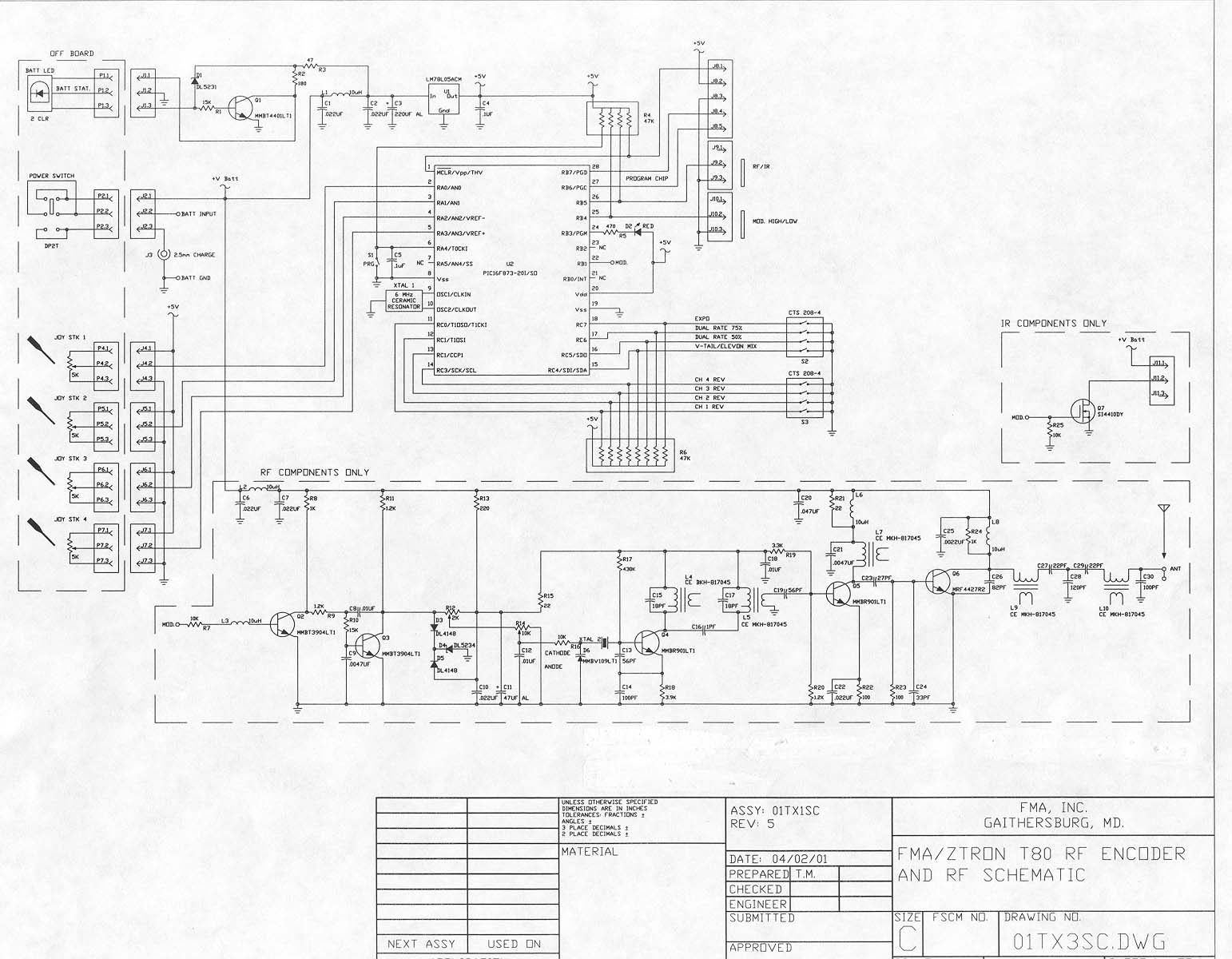
T80 FILTER CIRCUITS 6/21/01 1. Spurious emissions are suppressed by the bandpass filter formed by L$ &L5 in the oscillator/modulator. The combination of bandpass filter and modulation shaping keeps the occupied spectrum well within FCC requirements. 2. Sub-harmonics are suppressed by these same circuits and by wave traps on the 1 st and 2 nd stages. 3. Harmonics are suppressed in-part by the above circuits but primarily by the output network formed by L9; L10; c27; c28; c29 and c30. T80 CIRCUITS TO STABILIZE THE OUTPUT FREQUENCY 6/21/01 1. The Crystal controlled fundamental oscillator controls output fequency and is “rubbered” via a varactor diode at fundamental to be Frequency Shift Keyed (FSK) by a pulsed audio from the encoder. The audio pulse train is repetitive at 50 frames per second and consists of a synchronization pulse followed by six modulation pulses separated in sequence by from 1.0 ms to 2.0 ms; followed by a five millisecond synchronization pause that permits the decoder in the receiver to reset. 2. XTAL 2 is a fundamental crystal with an fo = 1/5 the desired transmit frequency. 3. The modulation input is applied to the tuning network via a Miller Integrator formed by Q3; Q4 and the discrete components between. The MI shapes the modulation pulses to form nearly the ideal trapezoidal modulation. 4. L4 and L5 is a multiplier set up as a bandpass filter to reduce occupied modulation spectrum. Q5 and attached discretes is a buffer, multiplier and amplifier.
Parts List/Tune Up Info
T80 TRANSMITTER TUNING AND ALIGNMENT SPECIFICATION JUNE 19, 2001 SAVED AS FILE: C:/WINWORD/FMA/T80TUNE 1. EQUIPMENT REQUIRED: a. Hewlett Packard Model 53131A 225 Mhz Universal Counter; S/N 9416A06729 b. Hewlett Packard Model HP8648A Signal Generator 100KHz to 100MHz c. Agilent E4411B 5KHz to 1.5 GHz ESA-L series Spectrum Analyzer d. Bird Wattmeter Model 43 with one(1) watt 60-80MHz Model 060-1 element e. one ¼ wavelength dipole antenna with 50 ohm match cable and BNC connectors and cable. f. Charged 9.6V Ni Cd power source. g. Wood test bench. h. Heathkit 50 ohm match “Cantenna”, oil filled load. 2. GENERAL: a. The HP 53131A is the primary frequency standard and shall have a current calibration record on file. b. At least twice daily, the HP 8646A Signal Generator shall be calibrated using the primary frequency standard and the calibration posted and set on the signal generator for tuning at 72 MHz band center frequency and at the 75 MHz band center frequency, whichever is applicable to the UUT. c. At least twice daily, the Agilent E144B Spectrum Analyzer shall be calibrated by connecting directly from the output of the HP8646A Signal Generator to the input of the Spectrum Analyzer. Calibration bias shall be noted and set on the Spectrun Analyzer. d. The UUT for the T80 is designed to radiate well below the permissible level for R/C transmitters and the Bird Wattmeter is sufficiently accurate to confirm peak power into a 50 ohm source. The “Cantenna” forms an adequate load for power testing and suppresses radiation adequately to permit other activities in the facility. 3. TEST SET UP Insure that the UUT is functional by observing and “rough tuning” against the spectrum analyzer. Once the UUT is roughly aligned and generating RF power, proceed with the alignment. a. Confirmation of radiated power: 1) Connect from antenna output for the UUT to the Bird Wattmeter using a 50 ohm RG58U cable with a BNC connector to the wattmeter. 2) Connect from the wattmeter to the “Cantenna” using an RG58U cable with BNC ends. 3) Set the element of the wattmeter for radiated power(Arrow pointing to the right) 4) Apply power to the UUT. 5) Tune L4 and L5 for max radiation. These coils are a bandpass filter, so they interact and tuning must be iterated. 6) Tune L7; L9; and L10 for peak output power. You are tuning the output for a 50 ohm match with the wattmeter. The “Cantenna” is also a 50 ohm match, so no mismatch is present and the output reading will be reasonably accurate. Expect max power to be >400 milliwatts and < 500 milliwatts. Power must not exceed 700mw. 7) Remove the test cables, wattmeter, and “Cantenna”. b. Align the UUT 1) Install the standard collapsible antenna to the transmitter and extend fully to 39 ½ inches. 2) Calibrate the spectrum analyzer using the counter and the Signal Generator. 3) Connect the ¼ wavelength antenna to the spectrum analyzer input connector. 4) Set the analyzer for center frequency for f0; set Resolution Bandwidth to 3KHz; set span to 5 KHz per division. 5) Align L7; L9 & L10 for maximum output power. NOTE: the antenna is never exactly a 50 ohm match, so your setting will differ a bit from those that created the 50 ohm match into the wattmeter. 6) Observe the spectrum with normal PPM modulation applied from the encoder. Adjust R12 and R14 such that center frequency is exactly f0 and the modulation peaks are f0 +&- 1500 Hz(# KHz deviation) 7) Proper occupied spectrum shall be </= to FCC required. 8) Reduce the analyzer antenna length to ¼ wavelength for 2 F0. 9) Increase analyzer span sufficiently to observe the 2 nd harmonic of F0. 10.Tune L9 and L10 to minimize 2 nd harmonic and observe that it is < FCC specification. 11. Recheck occupied spectrum and center frequency.
Test Report
ENGINEERING STATEMENT For Type Certification of FMA Direct Model: T-80RF FCC ID: KH8-RFD1 I am an Electronics Engineer, a principal the firm of Hyak Laboratories, Inc., Springfield, Virginia. My education and experience are a matter of record with the Federal Communications Commission. Hyak Laboratories, Inc. has been authorized by FMA Direct to make type certification measurements on the T-80RF transmitter. These tests were made by me or under my supervision in our Springfield laboratory. Test data and other documentation required by the FCC for type certification are included in this report. It is submitted that the above mentioned transmitter meets FCC requirements and type certification is requested. ______________________________ Rowland S. Johnson Dated: June 5, 2001 A. INTRODUCTION The following data are submitted in connection with this request for type certification of the T-80RF transmitter in accordance with Part 2, Subpart J of the FCC Rules. The T-80RF is a low power, non-voice, transmitter intended for remote control of model vehicle and model aircraft in the 72 - 76 MHz band. The equipment employs a vertical polarized antenna directly mounted on the unit and meets Paragraphs 95.645, 95.647, 95.649, and the technical requirements established in the Report & Order in PR Docket 90-222. B. GENERAL INFORMATION REQUIRED FOR TYPE CERTIFICATION (Paragraph 2.983 of the Rules) 1. Name of applicant: FMA Direct 2. Identification of equipment: FCC ID: KH8-RFD1 a. The equipment identification label is submitted as a separate exhibit. b. Photographs of the equipment are submitted as separate exhibits. 3. Quantity production is planned. 4. Technical description: a. 6k00F1D emission b. Frequency range: 72.01 – 75.99 MHz. c. Operating power of transmitter is fixed at the factory at 0.050 Watt – ERP(d). d. Maximum power permitted under Paragraph 95.635(b) of the FCC Rules is 750 milliwatts, and the T-80RF fully complied with those power limitations. e. The dc voltage and dc currents at final amplifier: Collector voltage: 10.2 Vdc Collector current: 90 mA f. Function of each active semiconductor device: See Appendix 1. g. Complete schematic diagram is submitted as a separate exhibit. h. Draft instruction book is submitted as a separate exhibit. 2 B. GENERAL INFORMATION (continued) i. The transmitter tune-up procedure is submitted as a separate exhibit. j. A description of circuits for stabilizing frequency is included in Appendix 2. k. A description of circuits and devices employed for suppression of spurious radiation and for limiting modulation is included in Appendix 3. l. Not applicable. 5. Data for 2.985 through 2.997 follow this section. 6. RF_Power_Output (Paragraph 2.985(a) of the Rules) Since the T-80RF has an immediately attached, integral antenna, no antenna port exists. Power was determined by substitution comparison. Assuming an ideal dipole (not the actual monopole) ERP(d) = 0.050 watts. C. MODULATION CHARACTERISTICS Occupied_Bandwidth (Paragraphs 2.989(i), and 95.635(b) of the Rules) Figure 1 is a plot of the sideband envelope of the transmitter taken with an Tektronix 494P spectrum analyzer. Modulation corresponded to conditions of 2.989(i) and consisted of the multiple pulses and synchronizing space normally used in radio control applications. (Modulation is achieved by a varicad shunting the crystal oscillator resulting in FM.) Operator controls were adjusted for worst- case emission. The plot is within the limits imposed by paragraph 95.635(c). The horizontal scale (frequency) is 10 kHz per division and the vertical scale (Amplitude) is a logarithmic presentation equal to 10 dB per division. Resolution bandwidth was 1 kHz; video bandwidth was 100 kHz. Figure 2 is a plot from a Tektronix 494P spectrum analyzer with 2 mS/division sweep in the time domain of the modulated carrier. Modulation consisted of five bursts with a nominal 0.8 mS duration at a nominal 125 Hz repetition rate. 3 FIGURE 1 OCCUPIED BANDWIDTH 95.635: (3) At least 25 dB on any frequency removed from the center of the authorized bandwidth by more than 50% up to and including 100% of the authorized bandwidth (4 to 8 kHz). (10) At least 45 dB on any frequency removed from the center of the authorized bandwidth by more than 100% up to and including 125% of the authorized bandwidth. (8 to 10 kHz) (11) At least 55 dB on any frequency removed from the center of the authorized bandwidth by more than 125% up to and including 250% of the authorized bandwidth. (10 to 20 kHz) (12) At least 56+10 log 10 (TP) dB on any frequency removed from the center of the authorized bandwidth by more than 250%. OCCUPIED BANDWIDTH FCC ID: KH8-RFD1 FIGURE 1 4 FIGURE 2 MODULATING WAVEFORM TIME DOMAIN 10 millisecond/division sweep, time domain OCCUPIED BANDWIDTH (Modulating Waveform) FCC ID: KH8-RFD1 FIGURE 2 5 D. SPURIOUS EMISSIONS AT THE ANTENNA TERMINALS (Paragraph 2.991 of the Rules) Since the T-80RF transmitter meets FCC Rules 95.645, there are no provisions for antenna terminal output measurements. Substitution of a suitable matching network and retuning to permit observations at 50 ohms would not be representative of normal operation. Accordingly data on radiated spurious emissions are included in lieu of antenna terminal conducted spurious emissions. E. MEASUREMENTS OF SPURIOUS RADIATION (Paragraph 2.993(a) (b) (2) of the Rules) Measurements of radiated spurious emissions from the T-80RF were made with a Tektronix 494P spectrum analyzer using EMCO 3121C calibrated test antennas using substitution comparison. The transmitter and its integral vertical antenna were located in an open field 3 meters from the test antenna. Supply voltage was from a fresh set of batteries with a terminal voltage under load of 10.7 Vdc. The transmitter and test antennas were arranged to maximize pickup. Both vertical and horizontal test antenna polarization were employed. Reference was power at the carrier frequency. The measurement system was capable of…
Text truncated - open the document above for the full version.
Contact Information
Applicant
Tim Marks
Test Firm
Hyak Laboratories, Inc.Rowland Johnson
703-451-1188
Technical Specifications
| # | Rule Parts | Frequency Range | Power Output | Emission | Tolerance |
|---|---|---|---|---|---|
| 1 | 95C | 72.01 MHz - 75.99 MHz | 50.00 mW | 6K00F1D | 0.0020000000 % |
Other Applications from FMA Inc
KH8-T2000
Feb 06, 1994CYY - Communications Receiver used w/Pt 15 Transmitter
Equipment Class
CYY - Communications Receiver used w/Pt 15 TransmitterKH8-2MCF8AM
May 02, 1993CYY - Communications Receiver used w/Pt 15 Transmitter
Equipment Class
CYY - Communications Receiver used w/Pt 15 Transmitter