KJA504830225Booster Amplifier
Aerocomm Inc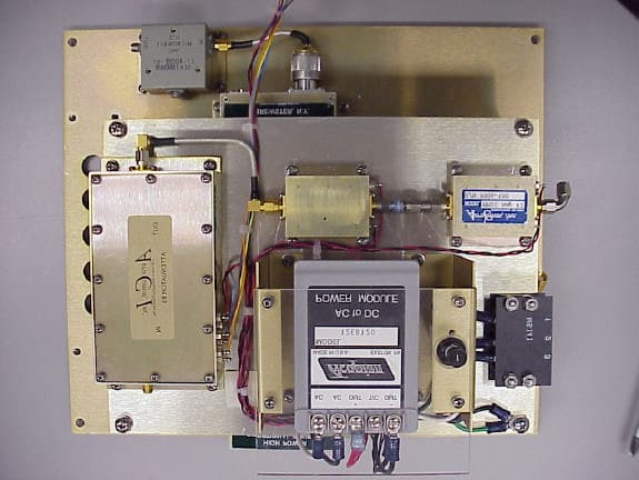
Click to zoom
Application Details
- Equipment Class
- AMP - Amplifier
- Date of Grant
- Apr 10, 2000
- Application Purpose
- Original Equipment
- Date of Application
- Sep 12, 1999
- Equipment Note
- Booster Amplifier
- Frequency Range
- 821.00000000 - 824.00000000
- Company
- Aerocomm Inc
- Country
- United States
Documents & Files
Document Text
Text extracted from the exhibit documents filed with the FCC. Open a document above to read the original.
Users Manual
19516 Amaranth Drive Germantown, MD 20874 Phone 301-540-0700 Fax 301-540-5743 PROGRAMMABLE BI-DIRECTIONAL BOOSTER AMPLIFIER PBBA OPERATION INSTRUCTION MANUAL MODEL 50289-RBA-800MHz ALL INFORMATION CONTAINED IN THIS DOCUMENT IS PROPRIETARY TO AEROCOMM, AND SHALL NOT BE RELEASED, DISCLOSED OR DUPLICATED FOR ANY PURPOSE OTHER THAN EVALUATION, INSPECTION, OR MAINTENANCE OF EQUIPMENT DELINEATED HEREIN. AEROCOMM IS NOT RESPONSIBLE FOR ANY EQUIPMENT REPAIRED OR ALTERED BY PERSONS NOT AUTHORIZED BY AEROCOMM, OR NOT IN ACCORDANCE WITH INSTRUCTIONS FURNISHED BY AEROCOMM. AEROCOMM IS NOT RESPONSIBLE FOR EQUIPMENT RENDERED DEFECTIVE AS A RESULT OF MISUSE, IMPROPER REPAIR, OR ABNORMAL CONDITIONS OF OPERATION, NOR DOES AEROCOMM ASSUME ANY LIABILITY FOR ANY CONSEQUENTIAL DAMAGE CAUSED BY SUCH EQUIPMENT. SERVICE CONTRACTS OR CUSTOMER ASSISTANCE AGREEMENTS ARE AVAILABLE FOR AEROCOMM PRODUCTS THAT REQUIRE MAINTENANCE AND/OR REPAIR. AEROCOMM ALSO HAS AVAILABLE SERVICE AND CONSULTATION CONTRACTS FOR ENTIRE SYSTEMS CONFIGURATIONS. ACI-OIM-0001 RELEASED ER # AC—0010 9/16/992 PROGRAMMABLE BI-DIRECTIONAL BOOSTER AMPLIFIER PBBA MODEL 50289-RBA-800MHz P/N 50483-02-25 ACI-OIM-0001 RELEASED ER # AC—0010 9/16/993 TABLE OF CONTENTS I.INTRODUCTION................................................................................................................................. 4 PURPOSE OF MANUAL: ......................................................................................................................... 4 GENERAL SYSTEM OVERVIEW:.......................................................................................................... 5 PROGRAMMABLE BI-DIRECTIONAL BOOSTER AMPLIFIER OVERVIEW:.................................. 6 II. SPECIFICATIONS............................................................................................................................... 8 GENERAL SPECIFICATIONS: ................................................................................................................ 8 PROGRAMMABLE BI-DIRECTIONAL BOOSTER AMPLIFIER .......................................................... 8 SUB-ASSEMBLY SPECIFICATIONS: ....................................................................................................9 ATTENUATOR AMP MODULE #1 & #2 ............................................................................................... 9 ATTENUATOR AMP MODULE #3 ........................................................................................................9 MMIC #1............................................................................................................................................... 10 MMIC #2............................................................................................................................................... 10 III.INSTALLATION ............................................................................................................................ 11 IV. EQUIPMENT INITIALIZATION ............................................................................................... 12 V. MAINTENANCE SCHEDULE ........................................................................................................13 VI. THEORY OF OPERATION.........................................................................................................14 VII. TROUBLESHOOTING ................................................................................................................ 15 III.SCHEMATICS................................................................................................................................ 16 ASSEMBLY DRAWINGS, PARTS LISTS .............................................................................................. 16 PROGRAMMABLE BI-DIRECTIONAL BOOSTER AMP ................................................................... 17 ATTENUATOR/AMPLIFIER MODULE #1 & #2.................................................................................. 18 ATTENUATOR/AMPLIFIER MODULE #3........................................................................................... 19 MMIC AMPLIFIER #1 ............................................................................................................................ 20 MMIC AMPLIFIER #2 ............................................................................................................................ 21 RBA BPF MODULE ................................................................................................................................ 22 IX. PERTINENT DOCUMENTATION............................................................................................. 23 X. RECOMMENDED SPARES ............................................................................................................ 24 ACI-OIM-0001 RELEASED ER # AC—0010 9/16/994 I. INTRODUCTION PURPOSE OF MANUAL: The purpose of this manual is to outline the installation, describe the operation, and assist in the maintenance and trouble-shooting of the Programmable Bi-directional Booster Amplifier (PBBA), Model 50289-RBA-800MHz. MANUAL OUTLINE: Section II: Section II covers the general specifications of the PBBA. This section outlines the general, mechanical and electrical specifications including the module specifications (sub-assemblies). Section III: Section III covers the instructions for installing the PBBA. Section IV:Section IV covers equipment initialization. Section V:Section V is the recommended schedule of periodic maintenance of the PBBA. Section VI:Section VI covers the general “Theory of Operation” of the logic and RF modules of a PBBA. This section is designed to aid in the understanding of the PBBA. Section VII:Section VII consists of diagrams, tables and procedures to assist in the troubleshooting of a PBBA. This section is designed to guide a technician in locating system fault(s) to the module. Included in the section is a list of recommended test equipment. Section …
Text truncated - open the document above for the full version.
Users Manual
1 PROGRAMMABLE BI-DIRECTIONAL BOOSTER AMPLIFIER PBBA OPERATION INSTRUCTION MANUAL MODEL 50289-RBA-800MHz MD Office: 19516 Amaranth Drive Germantown, MD 20874 Phone 301-540-0700 Fax 301-540-5743 NJ Office: 560 Sylvan Avenue, 3 rd Floor Englewood Cliffs, NJ 07632 Phone 201-227-0066 Fax 201-227-0067 Email [email protected] http://www.aerocomm.cc ALL INFORMATION CONTAINED IN THIS DOCUMENT IS PROPRIETARY TO AEROCOMM, AND SHALL NOT BE RELEASED, DISCLOSED OR DUPLICATED FOR ANY PURPOSE OTHER THAN EVALUATION, INSPECTION, OR MAINTENANCE OF EQUIPMENT DELINEATED HEREIN. AEROCOMM IS NOT RESPONSIBLE FOR ANY EQUIPMENT REPAIRED OR ALTERED BY PERSONS NOT AUTHORIZED BY AEROCOMM, OR NOT IN ACCORDANCE WITH INSTRUCTIONS FURNISHED BY AEROCOMM. AEROCOMM IS NOT RESPONSIBLE FOR EQUIPMENT RENDERED DEFECTIVE AS A RESULT OF MISUSE, IMPROPER REPAIR, OR ABNORMAL CONDITIONS OF OPERATION, NOR DOES AEROCOMM ASSUME ANY LIABILITY FOR ANY CONSEQUENTIAL DAMAGE CAUSED BY SUCH EQUIPMENT. SERVICE CONTRACTS OR CUSTOMER ASSISTANCE AGREEMENTS ARE AVAILABLE FOR AEROCOMM PRODUCTS THAT REQUIRE MAINTENANCE AND/OR REPAIR. AEROCOMM ALSO HAS AVAILABLE SERVICE AND CONSULTATION CONTRACTS FOR ENTIRE SYSTEMS CONFIGURATIONS. 2 PROGRAMMABLE BI-DIRECTIONAL BOOSTER AMPLIFIER PBBA MODEL 50289-RBA-800MHz P/N 50483-02-25 3 TABLE OF CONTENTS I. INTRODUCTION................................................................................................................................................4 PURPOSE OF MANUAL:........................................................................................................................................4 GENERAL SYSTEM OVERVIEW:.......................................................................................................................5 PROGRAMMABLE BI-DIRECTIONAL BOOSTER AMPLIFIER OVERVIEW:......................................6 II. SPECIFICATIONS..............................................................................................................................................8 GENERAL SPECIFICATIONS:..............................................................................................................................8 SUB-ASSEMBLY SPECIFICATIONS:.................................................................................................................9 ATTENUATOR AMP MODULE..........................................................................................................................9 MMIC #1..................................................................................................................................................................9 MMIC #2..................................................................................................................................................................9 III. INSTALLATION...........................................................................................................................................10 IV. OPERATION OF EQUIPMENT.............................................................................................................11 V. MAINTENANCE SCHEDULE.....................................................................................................................12 VI. THEORY OF OPERATION......................................................................................................................13 VII. TROUBLESHOOTING..............................................................................................................................14 III. SCHEMATICS,..............................................................................................................................................15 ASSEMBLY DRAWINGS, PARTS LISTS..........................................................................................................15 PROGRAMMABLE BI-DIRECTIONAL BOOSTER AMP............................................................................16 ATTENUATOR/AMPLIFIER MODULE #1......................................................................................................17 MMIC AMPLIFIER #1............................................................................................................................................18 MMIC AMPLIFIER #2............................................................................................................................................19 IX. PERTINENT DOCUMENTATION........................................................................................................20 X. RECOMMENDED SPARES..........................................................................................................................21 4 I. INTRODUCTION PURPOSE OF MANUAL: The purpose of this manual is to outline the installation, describe the operation, and assist in the maintenance and trouble-shooting for the Programmable Bi-directional Booster Amplifier (PBBA), Model 50289-RBA-800MHz. MANUAL OUTLINE: Section II: Section II covers the general specifications of the PBBA. This section outlines the general, mechanical and electrical specifications including the module specifications (sub-assemblies). Section III: Section III covers the instructions for installing the PBBA, site requirements, and equipment initialization. Section IV: Section IV cover operating procedures. Section V: Section V is the recommended schedule of periodic maintenance of the PBBA. Section VI: Section VI covers the general “Theory of Operations” of the logic and modules of a PBBA. This section is designed to aid in the understating of the PBBA. Section VII: Section VIII consists of diagrams, tables and procedures to assist in the troubleshooting of an PBBA. This section is designed to guide a technician in locating system fault(s) to the module. Included in the section is a list of recommended test equipment. Section VIII: Section IX consists of the schematic, assembly drawings, and parts list of the PBBA and it’s sub assemblies/ Section IX: Section X…
Text truncated - open the document above for the full version.
External Photos
Clinet: Aero Com, Inc.Report No. #: 9200-01 FCC ID: KJA504830225Issue Date: August 30, 1999 Model: 502890-RBA-800MHz Page 1 of 7 EXTERNAL PHOTOS Prepared on behalf of: Aero Comm, Inc. 19516 Amaranth Drive Germantown, MD 20874 FCC ID #:KJA504830225 Form 731 Confirmation #:EA95399 Clinet: Aero Com, Inc.Report No. #: 9200-01 FCC ID: KJA504830225Issue Date: August 30, 1999 Model: 502890-RBA-800MHz Page 2 of 7 CONDUCTED TEST - Front view Clinet: Aero Com, Inc.Report No. #: 9200-01 FCC ID: KJA504830225Issue Date: August 30, 1999 Model: 502890-RBA-800MHz Page 3 of 7 CONDUCTED TEST - Back view Clinet: Aero Com, Inc.Report No. #: 9200-01 FCC ID: KJA504830225Issue Date: August 30, 1999 Model: 502890-RBA-800MHz Page 4 of 7 RADIATED TEST – Front view Clinet: Aero Com, Inc.Report No. #: 9200-01 FCC ID: KJA504830225Issue Date: August 30, 1999 Model: 502890-RBA-800MHz Page 5 of 7 RADIATED TEST – Back view Clinet: Aero Com, Inc.Report No. #: 9200-01 FCC ID: KJA504830225Issue Date: August 30, 1999 Model: 502890-RBA-800MHz Page 6 of 7 PHOTOGRAPH OF EUT – Front view Clinet: Aero Com, Inc.Report No. #: 9200-01 FCC ID: KJA504830225Issue Date: August 30, 1999 Model: 502890-RBA-800MHz Page 7 of 7 PHOTOGRAPH OF EUT – Bottom View
External Photos
Figure 1: External Photo Top view Figure 2: External Photo Top View of Bottom Level
ID Label/Location Info
Clinet: Aero Com, Inc.Report No. #: 9200-01 FCC ID: KJA504830225Issue Date: August 30, 1999 Model: 502890-RBA-800MHz Page 1 of 3 FCC ID LABEL Prepared on behalf of: Aero Comm, Inc. 19516 Amaranth Drive Germantown, MD 20874 FCC ID #:KJA504830225 Form 731 Confirmation #:EA95399 Clinet: Aero Com, Inc.Report No. #: 9200-01 FCC ID: KJA504830225Issue Date: August 30, 1999 Model: 502890-RBA-800MHz Page 2 of 3 FCC ID Label The following are the label specifications for the FCC ID Label: FCC ID to be on label KJA504830225 Sample label (facsimile) -On following page Sketch of label placement-On following page Type of material-As shown on following page Size of type, FCC ID-As shown on following page Size of type, Statement-As shown on following page Label Dimensions-As shown on sample Method -permanently marking label-Indelibly printed Label attachment-Permanently glued FCC Statement-As shown on following page Clinet: Aero Com, Inc.Report No. #: 9200-01 FCC ID: KJA504830225Issue Date: August 30, 1999 Model: 502890-RBA-800MHz Page 3 of 3
ID Label/Location Info
Clinet: Aero Com, Inc.Report No. #: 9200-01 FCC ID: KJA504830225Issue Date: August 30, 1999 Model: 502890-RBA-800MHz Page 1 of 3 FCC ID LABEL Prepared on behalf of: Aero Comm, Inc. 19516 Amaranth Drive Germantown, MD 20874 FCC ID #:KJA504830225 Form 731 Confirmation #:EA95399 Clinet: Aero Com, Inc.Report No. #: 9200-01 FCC ID: KJA504830225Issue Date: August 30, 1999 Model: 502890-RBA-800MHz Page 2 of 3 FCC ID Label The following are the label specifications for the FCC ID Label: FCC ID to be on label KJA504830225 Sample label (facsimile) -On following page Sketch of label placement-On following page Type of material-As shown on following page Size of type, FCC ID-As shown on following page Size of type, Statement-As shown on following page Label Dimensions-As shown on sample Method -permanently marking label-Indelibly printed Label attachment-Permanently glued FCC Statement-As shown on following page Clinet: Aero Com, Inc.Report No. #: 9200-01 FCC ID: KJA504830225Issue Date: August 30, 1999 Model: 502890-RBA-800MHz Page 3 of 3
Internal Photos
Clinet: Aero Com, Inc.Report No. #: 9200-01 FCC ID: KJA504830225Issue Date: August 30, 1999 Model: 502890-RBA-800MHz Page 1 of 6 INTERNAL PHOTOS Prepared on behalf of: Aero Comm, Inc. 19516 Amaranth Drive Germantown, MD 20874 FCC ID #:KJA504830225 Form 731 Confirmation #:EA95399 Clinet: Aero Com, Inc.Report No. #: 9200-01 FCC ID: KJA504830225Issue Date: August 30, 1999 Model: 502890-RBA-800MHz Page 2 of 6 PHOTOGRAPH OF EUT- Controller Board Component Side View Clinet: Aero Com, Inc.Report No. #: 9200-01 FCC ID: KJA504830225Issue Date: August 30, 1999 Model: 502890-RBA-800MHz Page 3 of 6 PHOTOGRAPH OF EUT- Controller Board Trace Side View Clinet: Aero Com, Inc.Report No. #: 9200-01 FCC ID: KJA504830225Issue Date: August 30, 1999 Model: 502890-RBA-800MHz Page 4 of 6 PHOTOGRAPH OF Bottom Internal Layer of EUT Clinet: Aero Com, Inc.Report No. #: 9200-01 FCC ID: KJA504830225Issue Date: August 30, 1999 Model: 502890-RBA-800MHz Page 5 of 6 PHOTOGRAPH OF Top Internal Layer of EUT Clinet: Aero Com, Inc.Report No. #: 9200-01 FCC ID: KJA504830225Issue Date: August 30, 1999 Model: 502890-RBA-800MHz Page 6 of 6 PHOTOGRAPH OF Overall Internal View
Internal Photos
Clinet: Aero Com, Inc.Report No. #: 9200-01 FCC ID: KJA504830225Issue Date: August 30, 1999 Model: 502890-RBA-800MHz Page 1 of 6 INTERNAL PHOTOS Prepared on behalf of: Aero Comm, Inc. 19516 Amaranth Drive Germantown, MD 20874 FCC ID #:KJA504830225 Form 731 Confirmation #:EA95399 Clinet: Aero Com, Inc.Report No. #: 9200-01 FCC ID: KJA504830225Issue Date: August 30, 1999 Model: 502890-RBA-800MHz Page 2 of 6 PHOTOGRAPH OF EUT- Controller Board Component Side View Clinet: Aero Com, Inc.Report No. #: 9200-01 FCC ID: KJA504830225Issue Date: August 30, 1999 Model: 502890-RBA-800MHz Page 3 of 6 PHOTOGRAPH OF EUT- Controller Board Trace Side View Clinet: Aero Com, Inc.Report No. #: 9200-01 FCC ID: KJA504830225Issue Date: August 30, 1999 Model: 502890-RBA-800MHz Page 4 of 6 PHOTOGRAPH OF Bottom Internal Layer of EUT Clinet: Aero Com, Inc.Report No. #: 9200-01 FCC ID: KJA504830225Issue Date: August 30, 1999 Model: 502890-RBA-800MHz Page 5 of 6 PHOTOGRAPH OF Top Internal Layer of EUT Clinet: Aero Com, Inc.Report No. #: 9200-01 FCC ID: KJA504830225Issue Date: August 30, 1999 Model: 502890-RBA-800MHz Page 6 of 6 PHOTOGRAPH OF Overall Internal View
Test Report
Client: Aero Comm, Inc. Report No.: 9200-01 FCC ID: KJA504830225Issue Date: August 30, 1999 Model: 502890-RBA-800MHz Page 2 of 39 Table of Contents ExhibitTitlePage Cover Page1 Table of Contents2 IEngineering Statements3 IIMeasurement Instrument List5 IIIEUT Information and Data6 IVBlock Diagram10 VEUT Configuration and Cables11 VIConducted Data12 VIIRadiated Data (Per Section 2.1053)14 VIIIData for CFR 47 Part 2.104115 Section 2.1046 –RF Power Output 16 Section 2.1047 –Modulation Characteristics 19 Sections 2.1049 (i) and 90.219 (b & c) - Emissions Mask 24 Section 2.1051 – Spurious Emissions at Antenna Terminal 38 IXCompliance Information39 Client: Aero Comm, Inc. Report No.: 9200-01 FCC ID: KJA504830225Issue Date: August 30, 1999 Model: 502890-RBA-800MHz Page 3 of 39 Exhibit I Engineering Statements This report has been prepared on behalf of Aero Comm, Inc. to certify a Class B Private Land Mobile Radio Service Bi-directional Signal Booster. The test was performed for above said device under Parts 2.1033 (c ) and Part 90 of the FCC Rules and Regulations. The test results found in this test report relate only to the items tested. EQUIPMENT UNDER TEST:Programmable Bi-Directional Signal Booster Model: 02890-RBA-800MHz Power Supply: Acopian Model# 12EB120 FCC ID:KJA504830225 APPLICABLE RULES:CFR 47 Part 2.1033 (c); 2.1046, 90.209, 90.219 EQUIPMENT CATEGORY:Repeater MEASUREMENT LOCATION: F-Squared Laboratories in Damascus, MD. Site description and attenuation data are on file with the FCC's Sampling and Measurement Branch at the FCC Laboratory in Columbia, MD. M EASUREMENT PROCEDURE:All measurements were performed according to the 1992 version of ANSI C63.4. A list of the measurement equipment can be found in Exhibit II. Client: Aero Comm, Inc. Report No.: 9200-01 FCC ID: KJA504830225Issue Date: August 30, 1999 Model: 502890-RBA-800MHz Page 4 of 39 Client: Aero Comm, Inc. Report No.: 9200-01 FCC ID: KJA504830225Issue Date: August 30, 1999 Model: 502890-RBA-800MHz Page 5 of 39 Exhibit II List of Measurement Instrumentation Equipment Type ManufacturerModel #Serial # Cal. Due Date Receiver SystemsRohde & SchwarzESMIDE23119Feb. 2000 LISN #1Solar8012-50-R-24-BNC910488Jan. 2000 LISN #2Solar8012-50-R-24-BNC933201Jan. 2000 Biconical AntennaCompliance Design Inc.B100383Jan. 2000 Biconical AntennaCompliance Design Inc.B200292Jan. 2000 Biconical AntennaCompliance Design Inc.B300318Jan. 2000 Horn AntennaAntenna Research AssociatesDRG-118/A1105Feb. 2000 Antenna MastCompliance Design Inc.M100NANA TurntableF 2 LaboratoriesSite 1NANA Isolator #1*UTE Microwave Inc.CT-1059-OTU6049** Isolator #2*UTE Microwave Inc.CT-1059-OTU6050** Combiner*Mini-CircuitsZESC-2-1115542** RF Signal Generator#1Giga-Tronics6061A9637902Jan. 2000 RF Signal Generator#2HPE4420B-1E5US38220249July 2000 Spectrum AnalyzerHP8391A3149A07546Feb. 2000 * Note1: Customer Provided Equipment **Note2: Calibrated with the Rohde & Schwarz receiver and the HP and Gigatronics Signal Generators Client: Aero Comm, Inc. Report No.: 9200-01 FCC ID: KJA504830225Issue Date: August 30, 1999 Model: 502890-RBA-800MHz Page 6 of 39 Exhibit III Equipment Under Test Information and Data TEST ITEM CONDITION: The equipment to be tested was received in good condition. Electrical and mechanical drawings are included in the Operation and Instruction manual as supplied in Exhibit XIII. T ESTING ALGORITHM: The EUT was driven with the highest input signal level permitted in both the forward and reverse signal path directions. The worst case emissions are recorded in the data tables. C ONDUCTED EMISSION TESTING: The EUT was placed on a 0.8 meter high, 1 X 1.5 meter non-conductive table. Power was provided to the EUT through a LISN bonded to a 3 X 2 meter ground plane. The LISN and peripherals were supplied power through a filtered AC power source. The output of the LISN was connected to the input of the receiver and emissions in the range 450kHz to 30 MHz were measured. The measurements were recorded using the quasi-peak values, and the resolution bandwidth during testing was 9kHz. All data for conducted emissions is found in Exhibit VI. R ADIATED EMISSIONS: SPURIOUS EMISSIONS TESTING The EUT was tested at a distance of 3 meters. The emissions were maximized by rotating the table and raising/lowering the antenna mounted on a 4 meter mast. Cable and peripheral positions were also varied to produce maximum emissions. Both horizontal and vertical field components were measured. The output of the antenna was connected to the input of the receiver and emissions were measured in the range 30MHz to 8.5 GHz. The measured values up to 1GHz with a resolution bandwidth of 120KHz are quasi-peak readings made at 3 meters. Emissions from 1 GHz to 8.5 GHz were measured with a resolution bandwidth of 1 MHz and placed in the average detector mode. All data for radiated spurious emissions is found in Exhibit VII. R ADIATED SPURIOUS EMISSION ANTENNA PORT TESTING: The EUT was tested near the spectrum analyzer and source signal generators with the shortest available length cables to insure correct data collection. The Forward and Reverse outputs of the EUT were connected to the EMI receiver input port and the emissions were measured as shown in Exhibit VII. The test was then repeated with the receiver input connected first to the Forward Channel input port followed by measurements from the Reverse Channel input port. Client: Aero Comm, Inc. Report No.: 9200-01 FCC ID: KJA504830225Issue Date: August 30, 1999 Model: 502890-RBA-800MHz Page 7 of 39 INTERMODULATION DISTORTION AND EMISSIONS MASK TESTING: The EUT was tested by the use of 2 signal generators, 1 combiner, and 2 isolators in line with each signal generator. The output of the EUT was connected to the receiver and the emissions were measured as shown in Exhibit VIII. C ALCULATION OF DATA #1: RADIATED EMISSIONS - The antenna factors (including cable losses) of the biconical antennas were used along with the pre-amplifier gain, which were e…
Text truncated - open the document above for the full version.
Test Report
Client: Aero Comm, Inc. Report No.: 9200-01 FCC ID: KJA504830225Issue Date: August 30, 1999 Model: 502890-RBA-800MHz Page 2 of 39 Table of Contents ExhibitTitlePage Cover Page1 Table of Contents2 IEngineering Statements3 IIMeasurement Instrument List5 IIIEUT Information and Data6 IVBlock Diagram10 VEUT Configuration and Cables11 VIConducted Data12 VIIRadiated Data (Per Section 2.1053)14 VIIIData for CFR 47 Part 2.104115 Section 2.1046 –RF Power Output 16 Section 2.1047 –Modulation Characteristics 19 Sections 2.1049 (i) and 90.219 (b & c) - Emissions Mask 24 Section 2.1051 – Spurious Emissions at Antenna Terminal 38 IXCompliance Information39 Client: Aero Comm, Inc. Report No.: 9200-01 FCC ID: KJA504830225Issue Date: August 30, 1999 Model: 502890-RBA-800MHz Page 3 of 39 Exhibit I Engineering Statements This report has been prepared on behalf of Aero Comm, Inc. to certify a Class B Private Land Mobile Radio Service Bi-directional Signal Booster. The test was performed for above said device under Parts 2.1033 (c ) and Part 90 of the FCC Rules and Regulations. The test results found in this test report relate only to the items tested. EQUIPMENT UNDER TEST:Programmable Bi-Directional Signal Booster Model: 02890-RBA-800MHz Power Supply: Acopian Model# 12EB120 FCC ID:KJA504830225 APPLICABLE RULES:CFR 47 Part 2.1033 (c); 2.1046, 90.209, 90.219 EQUIPMENT CATEGORY:Repeater MEASUREMENT LOCATION: F-Squared Laboratories in Damascus, MD. Site description and attenuation data are on file with the FCC's Sampling and Measurement Branch at the FCC Laboratory in Columbia, MD. M EASUREMENT PROCEDURE:All measurements were performed according to the 1992 version of ANSI C63.4. A list of the measurement equipment can be found in Exhibit II. Client: Aero Comm, Inc. Report No.: 9200-01 FCC ID: KJA504830225Issue Date: August 30, 1999 Model: 502890-RBA-800MHz Page 4 of 39 Client: Aero Comm, Inc. Report No.: 9200-01 FCC ID: KJA504830225Issue Date: August 30, 1999 Model: 502890-RBA-800MHz Page 5 of 39 Exhibit II List of Measurement Instrumentation Equipment Type ManufacturerModel #Serial # Cal. Due Date Receiver SystemsRohde & SchwarzESMIDE23119Feb. 2000 LISN #1Solar8012-50-R-24-BNC910488Jan. 2000 LISN #2Solar8012-50-R-24-BNC933201Jan. 2000 Biconical AntennaCompliance Design Inc.B100383Jan. 2000 Biconical AntennaCompliance Design Inc.B200292Jan. 2000 Biconical AntennaCompliance Design Inc.B300318Jan. 2000 Horn AntennaAntenna Research AssociatesDRG-118/A1105Feb. 2000 Antenna MastCompliance Design Inc.M100NANA TurntableF 2 LaboratoriesSite 1NANA Isolator #1*UTE Microwave Inc.CT-1059-OTU6049** Isolator #2*UTE Microwave Inc.CT-1059-OTU6050** Combiner*Mini-CircuitsZESC-2-1115542** RF Signal Generator#1Giga-Tronics6061A9637902Jan. 2000 RF Signal Generator#2HPE4420B-1E5US38220249July 2000 Spectrum AnalyzerHP8391A3149A07546Feb. 2000 * Note1: Customer Provided Equipment **Note2: Calibrated with the Rohde & Schwarz receiver and the HP and Gigatronics Signal Generators Client: Aero Comm, Inc. Report No.: 9200-01 FCC ID: KJA504830225Issue Date: August 30, 1999 Model: 502890-RBA-800MHz Page 6 of 39 Exhibit III Equipment Under Test Information and Data TEST ITEM CONDITION: The equipment to be tested was received in good condition. Electrical and mechanical drawings are included in the Operation and Instruction manual as supplied in Exhibit XIII. T ESTING ALGORITHM: The EUT was driven with the highest input signal level permitted in both the forward and reverse signal path directions. The worst case emissions are recorded in the data tables. C ONDUCTED EMISSION TESTING: The EUT was placed on a 0.8 meter high, 1 X 1.5 meter non-conductive table. Power was provided to the EUT through a LISN bonded to a 3 X 2 meter ground plane. The LISN and peripherals were supplied power through a filtered AC power source. The output of the LISN was connected to the input of the receiver and emissions in the range 450kHz to 30 MHz were measured. The measurements were recorded using the quasi-peak values, and the resolution bandwidth during testing was 9kHz. All data for conducted emissions is found in Exhibit VI. R ADIATED EMISSIONS: SPURIOUS EMISSIONS TESTING The EUT was tested at a distance of 3 meters. The emissions were maximized by rotating the table and raising/lowering the antenna mounted on a 4 meter mast. Cable and peripheral positions were also varied to produce maximum emissions. Both horizontal and vertical field components were measured. The output of the antenna was connected to the input of the receiver and emissions were measured in the range 30MHz to 8.5 GHz. The measured values up to 1GHz with a resolution bandwidth of 120KHz are quasi-peak readings made at 3 meters. Emissions from 1 GHz to 8.5 GHz were measured with a resolution bandwidth of 1 MHz and placed in the average detector mode. All data for radiated spurious emissions is found in Exhibit VII. R ADIATED SPURIOUS EMISSION ANTENNA PORT TESTING: The EUT was tested near the spectrum analyzer and source signal generators with the shortest available length cables to insure correct data collection. The Forward and Reverse outputs of the EUT were connected to the EMI receiver input port and the emissions were measured as shown in Exhibit VII. The test was then repeated with the receiver input connected first to the Forward Channel input port followed by measurements from the Reverse Channel input port. Client: Aero Comm, Inc. Report No.: 9200-01 FCC ID: KJA504830225Issue Date: August 30, 1999 Model: 502890-RBA-800MHz Page 7 of 39 INTERMODULATION DISTORTION AND EMISSIONS MASK TESTING: The EUT was tested by the use of 2 signal generators, 1 combiner, and 2 isolators in line with each signal generator. The output of the EUT was connected to the receiver and the emissions were measured as shown in Exhibit VIII. C ALCULATION OF DATA #1: RADIATED EMISSIONS - The antenna factors (including cable losses) of the biconical antennas were used along with the pre-amplifier gain, which were e…
Text truncated - open the document above for the full version.
Test Setup Photos
Clinet: Aero Com, Inc.Report No. #: 9200-01 FCC ID: KJA504830225Issue Date: August 30, 1999 Model: 502890-RBA-800MHz Page 1 of 2 TEST SET UP PHOTOS Prepared on behalf of: Aero Comm, Inc. 19516 Amaranth Drive Germantown, MD 20874 FCC ID #:KJA504830225 Form 731 Confirmation #:EA95399 Clinet: Aero Com, Inc.Re…
Text truncated - open the document above for the full version.
Contact Information
Applicant
Lee Masoiam(President)
301 540-0700Fax: 301 540-5743
Technical Contact
F2 EngineeringDale Royston
[email protected]301-253-4500
10880 Moxley Rd · Damascus, Maryland · United States
Non-Technical Contact
F2 EngineeringKaren D Worthington
[email protected]301-253-4500
Technical Specifications
| # | Rule Parts | Frequency Range | Power Output | Emission | Tolerance |
|---|---|---|---|---|---|
| 1 | 90 | 821 MHz - 824 MHz | 50.10 mW | F3E | Amp |
Other Applications from Aerocomm Inc
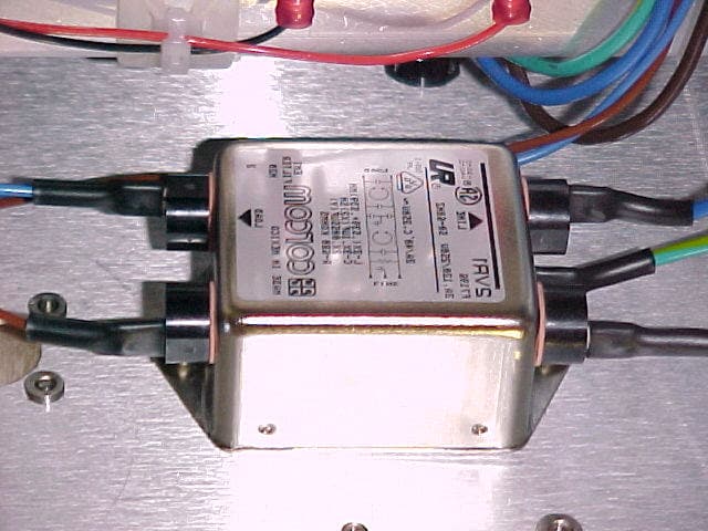
KJA514830111
Oct 22, 2001Cellular Over Fiber Cell Extender System
Equipment Class
TNB - Licensed Non-Broadcast Station Transmitter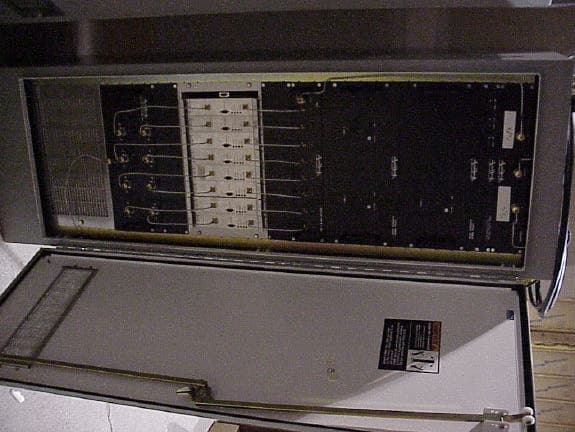
KJA504830202
Jul 04, 2000800 Mhz Signal Booster for tunnels
Equipment Class
TNB - Licensed Non-Broadcast Station Transmitter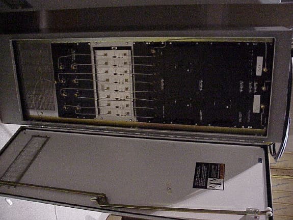
KJA504830203
Jul 04, 2000800 MHz Signal Booster
Equipment Class
TNB - Licensed Non-Broadcast Station Transmitter
KJA501540332
Jun 08, 2000Single Channel
Equipment Class
AMP - Amplifier
KJA501540302
May 24, 2000Non Broadcast Transmitter for radio Telemetry
Equipment Class
TNB - Licensed Non-Broadcast Station Transmitter