KN3910-924
Woo Ju Communications Co Ltd
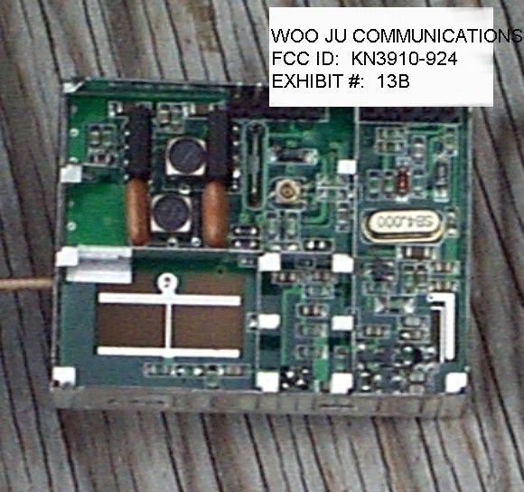
Click to zoom
Application Details
- Equipment Class
- DXX - Part 15 Low Power Communication Device Transmitter
- Date of Grant
- Mar 30, 1999
- Application Purpose
- Original Equipment
- Date of Application
- Mar 14, 1999
- Frequency Range
- 2407.00000000 - 2476.50000000
- Company
- Woo Ju Communications Co Ltd
- Country
- South Korea
Documents & Files
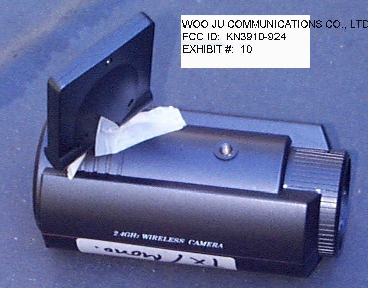
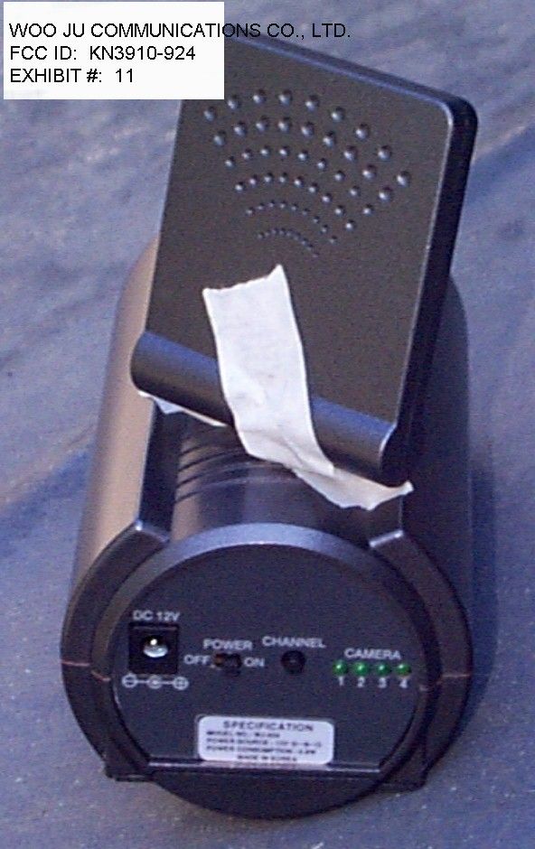
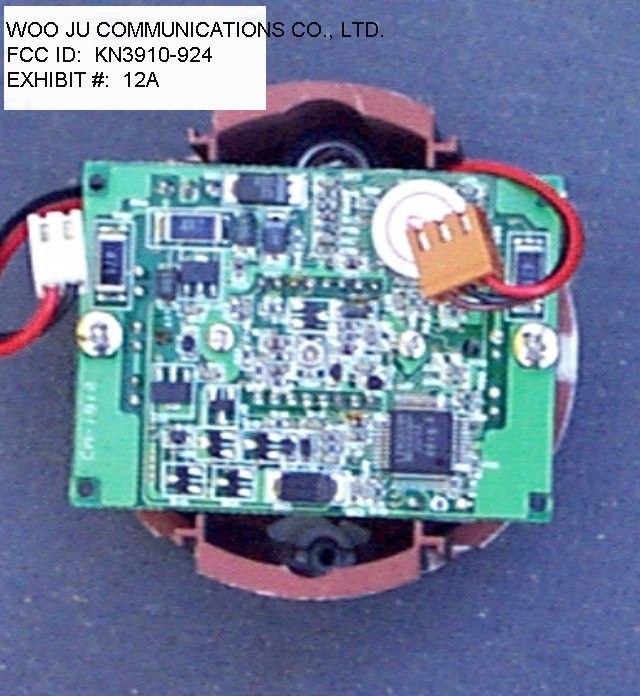
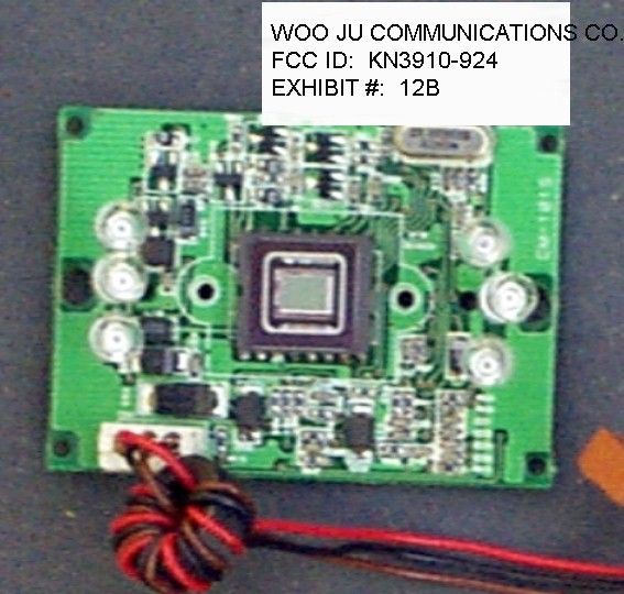
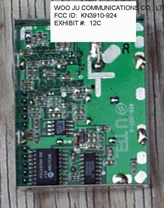
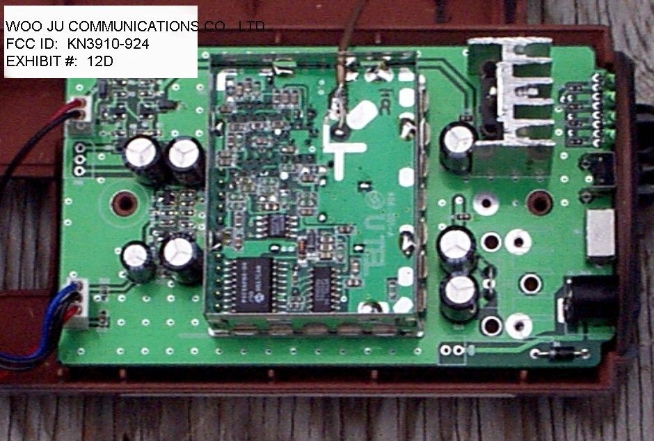
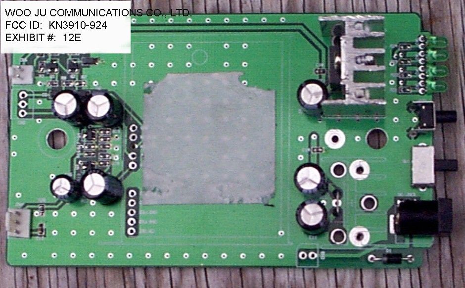
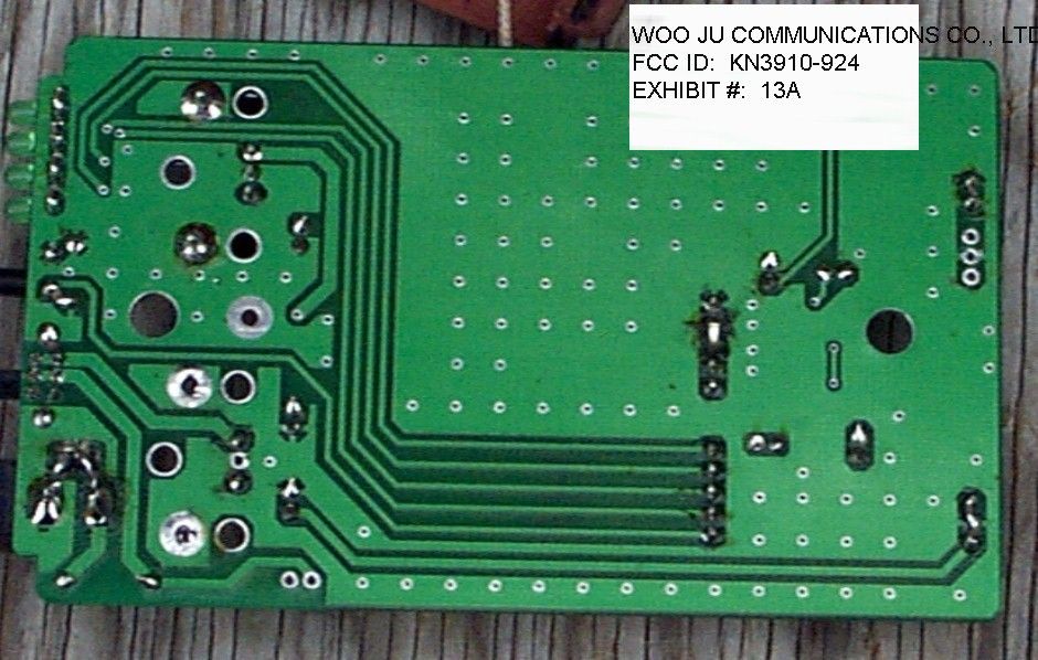
Document Text
Text extracted from the exhibit documents filed with the FCC. Open a document above to read the original.
Test Report
Fleetwood Group Inc. FCC ID: FBR-DL800B Operational Description Page 1 of 3 File Name: DLOPER.DOC Date: 07/02/01 Reply® DL Keypad Model CRS10000 Operational Description (Part 74) System Description: The Fleetwood Reply DL Wireless Response System is designed to provide a means of interactivity in a distance learning (multiple site) broadcast setting. This interactivity is accomplished by the Reply DL system in two ways: (1) by participant keypad entries (switch closure information) and (2) audio interaction via the internal wireless microphone. The keypad entries (numeric keys) are sent via modem to the host location to be incorporated in bar graphs, pie charts, or other graphical displays and the audio from the keypad when activated is fed to the host location via an analog phone line for rebroadcast to enable the other sites to hear comments and questions from other participants. The typical remote site may consist of as few as 6 to as many as 250 keypad units. Operation: During a normal session with the response system, a typical sequence may occur as follows: 1. Instruct the participants on the usage of the keypad units. 2. Ask a question and allow enough time (at least 10 seconds) for all participants to respond. 3. Observe the results on the PC screen and optionally save the results for later analysis if desired. 4. Proceed and repeat the process on the next question. 5. When a keypad talk request from a remote site is received, if desired activate the keypad microphone and broadcast the participant audio to all sites. 5. Continue until all questions are completed. General Characteristics: The base and keypad units are integrated by three functional subsystems. KEYPAD:BASE: CONTROL SIGNALS: 1. Address receiver⇐Address transmitter. 2. Response transmitterÞResponse receiver. AUDIO LINK: 1. UHF audio link transmitterÞAudio link receiver. Fleetwood Group Inc. FCC ID: FBR-DL800B Operational Description Page 2 of 3 File Name: DLOPER.DOC Date: 07/02/01 WIRELESS MICROPHONE LINK TRANSMITTER (KEYPAD): The voice link transmitter in the keypad allows microphone audio to be sent to the base unit to be sent in turn to the host site for rebroadcast to other remote sites. The transmitter is a low power device which has four subparts as referenced in the schematic diagram. • Synthesizer: The frequency synthesizer U7 locks the transmitter oscillator to the reference oscillator on one of four channels. When power is first applied to the link transmitter, information from U4 microprocessor is applied to synthesizer U7. The first data is channel information as preset by a keypad entry (channels 1-4). This information is loaded via a 3 wire serial interface to U7. The transmitter frequencies are preset by channel selection, and by the action of the RF programmable divider within U7. Operational commands (Atx-enable, Ser. Data, Ser. Clock) are also sent via the 3 wire control lines to U7. The reference oscillator in U4 is set to a frequency of 16.1 MHz. by crystal Y3. The frequency is adjusted by a voltage tuned varicap (VC2). The 16.1 MHz. signal is presented to the reference divider chain in U7 which is in a preset divide state. The Voltage Controlled Oscillator (VCO) signal from Q24, is applied to the main frequency divider of U7 which is preprogrammed by the channel selected (1-4). The VCO’s output signal, and the 16.1 MHz crystal output signal are each divided down to a common comparison frequency (see fig. 1). Both signals are then applied to the phase comparator of U7 to generate a VCO control voltage proportional to the frequency difference. In the VCO locked state, the two frequencies are equal and the VCO control voltage is stable. If frequency changes occur in the VCO, the control voltage will change to correct for the shift. The output control voltage from the phase comparator is passed thru a filter (C66&R96), and then to varicap VC4 which tunes and maintains the VCO to the desired frequency. FIG. 1 REPLY DL KEYPAD AUDIO TRANSMITTER FREQUENCY OPTIONS Formula f Mf R out xtl = Key f out = Output Frequency M = Multiplier f xtl = Crystal Frequency = 16.1 MHZ R = Reference Divider = 161 (Reference Frequency = 100 KHz) ChannelMultiplierOutput Frequency Fleetwood Group Inc. FCC ID: FBR-DL800B Operational Description Page 3 of 3 File Name: DLOPER.DOC Date: 07/02/01 18002800.2 MHZ 28023802.3 MHZ 38049804.9 MHZ 48033803.3 MHZ • Transmitter: Transmitter amplifier U6 is a monolithic integrated circuit which operates from a 5 Vdc single voltage supply. U6 has internal current regulation which minimizes gain changes over temperature. The transmitter is designed to operate over the range of 800.2 - 804.9 MHz. in continuous mode and conforms to FCC rules part 74 subpart h low power radiation and harmonic content. The 5V dc power is turned on and off by the action of microcontroller U4. When activated, the RF signal from the VCO is applied to the input of the transmitter's low pass filter- LPF (R100, L12,C71&C72). This filter is designed to prevent harmonic energy from reaching U6 from the VCO. The LPF is also configured to maintain a constant load to the input of amplifier U6 and thus ensure stability. The amplified signal of U6 is applied to the output LPF which functions the same as the input filter. To ensure signal purity a second LP filter is employed to help remove any possible harmonic content generated by U6 (C76,C77&L13). This LPF also is designed to match the output circuit of U6. The output signal from the second LP filter is applied to a tuned harmonic trap. This trap (C78,C81&L14), is designed to remove second harmonic energy from U6 and keep it from reaching the antenna. • •• •Antenna: The antenna tuner network(C82&C83) is designed to match the impedance of the transmitter to that of the antenna for best RF energy transfer. This network also performs the tuning of the antenna. The antenna is configured as an horizontal 1/4 λ circular radiator over a ground plane. This configuration creates cir…
Text truncated - open the document above for the full version.
Contact Information
Applicant
C H Lee(Manager)
Technical Contact
Non-Technical Contact
TIMCO ENGINEERING, INC.SHARON A HOFFMAN
[email protected]888-472-2424
Test Firm
Timco Engineering, Inc.Sid Sanders
Technical Specifications
| # | Rule Parts | Frequency Range | Power Output |
|---|---|---|---|
| 1 | 15C | 2.41 GHz - 2.48 GHz | - |
Other Applications from Woo Ju Communications Co Ltd

KN3910C-924C
Mar 30, 1999DXX - Part 15 Low Power Communication Device Transmitter
Equipment Class
DXX - Part 15 Low Power Communication Device TransmitterKN3WJ-900
Apr 23, 1997Wireless Camera Receiver
Equipment Class
HID - Part 15 TV Interface DeviceKN3CA-900
Mar 26, 1997Video Transmitter
Equipment Class
DXX - Part 15 Low Power Communication Device Transmitter