KOBDR06WAAutomotive Security/Convenience Receiver
Lear Corporation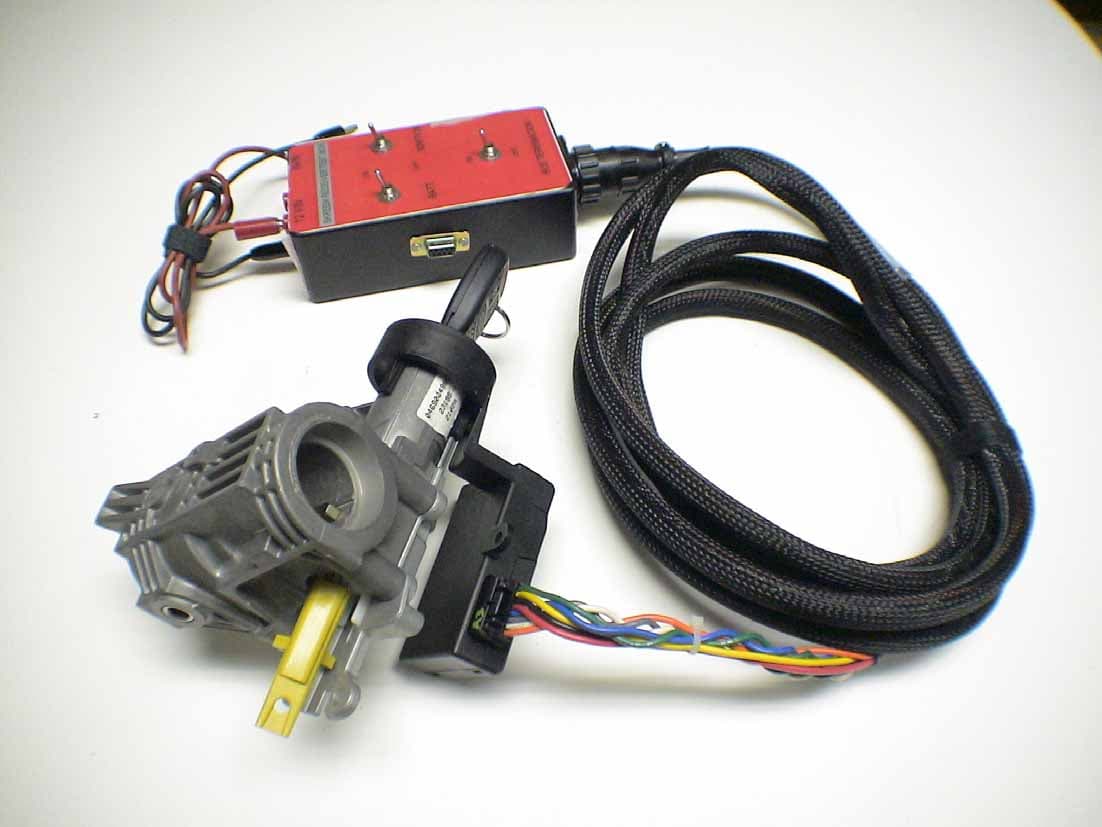
Click to zoom
Application Details
- Equipment Class
- CYY - Communications Receiver used w/Pt 15 Transmitter
- Date of Grant
- Mar 19, 2006
- Application Purpose
- Original Equipment
- Date of Application
- Mar 19, 2006
- Equipment Note
- Automotive Security/Convenience Receiver
- Frequency Range
- 315.00000000 - 315.00000000
- Company
- Lear Corporation
- Country
- United States
Documents & Files
Document Text
Text extracted from the exhibit documents filed with the FCC. Open a document above to read the original.
Users Manual
Re: Certification for Lear Composite Device Model(s): L0073843, L0073846, L0073847, L0073848, L0073851 FCC ID: KOBDR06WA IC: 3521A-DR06WA USER'S MANUAL INFORMATION (PRELIMINARY) The User's Manual is in preparation. The following material will be contained in the manual: FCC ID: KOBDR06WA IC: 3521A-DR06WA This device complies with Part 15 of the FCC Rules and with RSS-210 of Industry Canada. Operation is subject to the following two conditions: (1) This device may not cause harmful interference, and (2) This device must accept any interference received, including interference that may cause undesired operation. WARNING: Changes or modifications not expressively approved by the party responsible for compliance could void the user's authority to operate the equipment. The term “IC:” before the radio certification number only signifies that Industry Canada technical specifications were met.
Attestation Statements
Re: Certification for Lear Composite Device Model(s): L0073843, L0073846, L0073847, L0073848, L0073851 FCC ID: KOBDR06WA IC: 3521A-DR06WA POWER OF ATTORNEY A letter granting Valdis V. Liepa the Power of Attorney is on file and can be provided when so requested. Re: Certification for Lear Composite Device Model(s): L0073843, L0073846, L0073847, L0073848, L0073851 FCC ID: KOBDR06WA IC: 3521A-DR06WA REQUEST FOR CONFIDENTIALITY Pursuant to 47 CRF 0.459, Lear requests that a part of the subject application be held confidential. This comprises Exhibits (5) Schematics (10) Parts List (Part of Exhibit only) Lear has spent substantial effort in developing this product and it is one of the first of its kind in industry. Having the subject information easily available to "competition" would negate the advantage they have achieved by developing this product. Not protecting the details of the design will result in financial hardship. If there are any questions regarding this request, please contact me at the above address or call 734-483-4211, fax 734-647-2106 or e-mail [email protected]. Sincerely, Valdis V. Liepa Research Scientist University of Michigan March 18, 2006 Re: Certification for Lear Composite Device Model(s): L0073843, L0073846, L0073847, L0073848, L0073851 FCC ID: KOBDR06WA IC: 3521A-DR06WA STATEMENT OF MODIFICATIONS There were no modifications made to the DUT by this test laboratory. (Also see Section 3.1 of the attached Test Report). _____________________ Valdis V. Liepa Research Scientist Re: Certification for Lear Composite Device Model(s): L0073843, L0073846, L0073847, L0073848, L0073851 FCC ID: KOBDR06WA IC: 3521A-DR06WA GENERAL PRODUCT INFORMATION The device, for which certification is pursued, has been designed by: Lear Corporation 5200 Auto Club Drive Dearborn, MI 48126 Tom Tang Tel: 313-593 - 9934 Fax: 313-593-9526 It will be manufactured by: EPIC Technologies 200 East Bluegrass Dr. Norwalk, OH 44857 Tom Tang Tel: 313-593 - 9934 Fax: 313-593-9526 Canadian Contact: John J. Jackson Daimler-Chrysler Canada- ARDC 3939 Rhodes Drive Windsor, ON. N8W 5B5 Tel: (519) 973 – 2870 [email protected]
Block Diagram
5200 Auto Club Dr. Dearborn, Michigan 48126-9982 (313) 593-9000 Re: Certification for Lear Corporation Receiver, Model SKREEM FCC ID: KOBDR06WA IC: 3521A-DR06WA Riad Ghabra Page 1 Created on 2/5/2003 4:01 PM IC Block Diagram of Immobilizer System Operation Coil Key Ignition Lock Cylinder Transponder Coil Low Frequency Transceiver Module Battery Ground Ignition Bus 5200 Auto Club Dr. Dearborn, Michigan 48126-9982 (313) 593-9000 Re: Certification for Lear Corporation Receiver, Model NG WCM FCC ID: KOBDR06WA IC: 3521A-DR06WA Receiver Block Diagram - LNA Low Noise Amplifier Mixer 10.7MHz IF Filter Multi-Stage IF Amp PLL Synthesiser Crystal Oscillator Carrier Freq. Pre- Selector Antenna Data Slicer Envelope Detector Demodulated Data Other Oscillators: 16.000 MHz 10.178125 MHz 32.768 KHz
Cover Letter(s)
March 18, 2006 Federal Communications Commission Equipment Approval Services P.O. Box 358315 Pittsburgh, PA 15251-5315 Re: Certification for Lear Composite Device Model(s): L0073843, L0073846, L0073847, L0073848, L0073851 FCC ID: KOBDR06WA IC: 3521A-DR06WA Please find enclosed application materials for certification of Lear L0073843, L0073846, L0073847, L0073848, L0073851 Composite Device. We tested it and found it to comply with FCC Part 15. If there are any questions regarding the application or testing performed, please contact me at the above address or call 734-483-4211, fax 734-647-2106, or e-mail [email protected]. Sincerely, Valdis V. Liepa Research Scientist March 18, 2006 Certification and Engineering Bureau Industry Canada 3701 Carling Avenue, Bldg. 94 Ottawa, Ontario K2H 8S2 Re: Certification for Lear Composite Device Model(s): L0073843, L0073846, L0073847, L0073848, L0073851 FCC ID: KOBDR06WA IC: 3521A-DR06WA Please find enclosed application materials for certification of Lear L0073843, L0073846, L0073847, L0073848, L0073851 Composite Device. We tested the device and found it to comply with RSS-GEN/102/210. The product is identified by: IC: 3521A-DR06WA If there are any questions, suggestions, etc., regarding the application or testing performed, please contact me at the above address or call 734-483-4211, fax 734-647- 2106; e-mail: [email protected]. Sincerely, Valdis V. Liepa Research Scientist
Cover Letter(s)
March 18, 2006 American Telecommunications Certification Body, Inc. 6731 Whittier Avenue Suite C110 McLean, VA 22101 RE: Certification Application FCC ID: KOBDR06WA IC: 3521A-DR06WA Model(s): L0073843, L0073846, L0073847, L0073848, L0073851 Please find enclosed application materials for certification of Lear L0073843, L0073846, L0073847, L0073848, L0073851 Composite Device. Note: 1) portions of this submittal are filed Confidential 2) a list of the modifications made is provided in Attestations. If there are any questions regarding the application or testing performed, please contact me at the above address or call 734-483-4211, fax 734-647-2106, or e-mail [email protected]. Sincerely, Valdis V. Liepa Research Scientist
External Photos
DUT with Harness DUT case variations (top) DUT case variations (bottom)
ID Label/Location Info
5200 Auto Club Dr. Dearborn, Michigan 48126-9982 (313) 593-9000 Re: Certification for Lear Corporation Receiver, Model NG WCM FCC ID: KOBDR06WA IC: 3521A-DR06WA FCC and IC ID LABEL and STATEMENT The following drawings outline the 2 different cosmetic versions of this receiver with Immobilizer. The internal PCB is the same between all versions, however with different component population variation between Immobilizer and non-Immobilizer. The label(s) below will be laser etched on the outside and on the back of the plastic case of the transmitter. The following statement will be printed in the User’s Instruction Manual This device complies with Part 15 of the FCC Rules and with RSS-210 of the Industry Canada. Operation is subject to the following two conditions: (1) This device may not cause harmful interference, and (2) This device must accept any interference received, including interference that may cause undesired operation. WARNING: Changes or modifications not expressively approved by the party responsible for compliance could void the user’s authority to operate the equipment. L0073843 : HB WCM NA, RKE+SKIM, BASE TPM - WA L0073846 : LX WCM NA, RKE+SKIM, BASE TPM - WA L0073847 : LX WCM NA, RKE+SKIM, LIN TPM - WA L0073848 : WK WCM NA, RKE+SKIM, BASE TPM - WA L0073851 : WK WCM NA, RKE+SKIM, LIN TPM - WA
Internal Photos
DUT apart (top) DUT apart (bottom) PCB (top) PCB ( bottom )
Operational Description
5200 Auto Club Dr. Dearborn, Michigan 48126-9982 (313) 593-9000 Re: Certification for Lear Corporation Receiver, Model NG WCM FCC ID: KOBDR06WA IC: 3521A-DR06WA DESCRIPTION OF OPERATION GENERAL DESCRIPTION The product for which certification is pursued will be manufactured for DaimlerChrysler Motor Company by Lear Corporation for automotive applications. The module is intended to perform three functions: Vehicle immobilization, RKE (Remote Keyless Entry) and TPM (Tire Pressure Monitoring). There is a version that will not have the LF circuit populated and thus will be an RKE only module. The receiver section of the design is identical between the two different versions. The receiver is to be mounted in the vehicle and will work in conjunction with the 315 MHz handheld transmitter and tire sensors. The receiver base-station is part of a keyless entry system that can be used to perform certain functions such as lock and unlock of the driver and passenger doors, open the trunk, etc... depending on how the receiver module is programmed. The receiver is also part of a tire pressure monitoring system that take be used to check the pressure and/or temperature of the vehicle’s tires. There are different housings this receiver module will be mounted in and will have a DaimlerChrysler/Lear part number stamped on the back of the housing. The PCB, microprocessor and RF circuitry on all versions are identical. TECHNICAL DESCRIPTION When the buttons on the handheld transmitter is depressed, a RF modulated signal is generated that will only be recognized by a matched receiver matching the correct data protocol. The code is carried by 315 MHz carrier with AM OOK (on-off keying) modulation and demodulated by the receiver basestation. The data code is of a Manchester modulation format to express bits “0” and “1”. RF detection is accomplished with an off-board wire antenna internal to the receiver base-station. The receiver is of a super-heterodyne, single conversion, narrow band architecture that demodulates the RF transmission present on the off-board antenna. Demodulated data is then made available to the system microprocessor that decodes the transmitted message and performs the desired function. The local oscillator is a PLL crystal-based system with a frequency tolerance of ± 16kHz. When the tire sensors are actuated either by pressure, rotational force or triggered, a RF modulated signal is generated that will be recognized by a receiver matching the correct data protocol. The code is carried by 315 MHz carrier with FM FSK (frequency shift keying) modulation and demodulated by the receiver base-station. The data code is of a Manchester modulation format to express bits “0” and “1”. RF detection is accomplished with an off-board wire antenna internal to the receiver base-station. The receiver is of a super-heterodyne, single conversion, narrow band architecture that demodulates the RF transmission present on the off-board antenna. Demodulated data is then made available to the system microprocessor that decodes the transmitted message and performs the desired function. The local oscillator is a PLL crystal-based system with a frequency tolerance of ± 16kHz. 5200 Auto Club Dr. Dearborn, Michigan 48126-9982 (313) 593-9000 Re: Certification for Lear Corporation Receiver, Model NG WCM FCC ID: KOBDR06WA IC: 3521A-DR06WA The immobilization feature is based upon 125 kHz RFID technology. This feature is intended to ensure that the proper key is used to operate the vehicle. The encoder for the RKE function also contains the active circuitry for the immobilization feature. An on board parallel inductor/capacitor tank circuit acts as the 125 kHz receive antenna. When the key is placed into the ignition and turned, the receiver energizes a loop antenna resonant at 125 kHz +/- 7 kHz in order to power the immobilizer on the key (in the event that the cell in the key transmitter is depleted) and transfer data to the key’s immobilizer circuitry. Information and commands are transferred to the key’s circuitry by periodically interrupting the 125 kHz field for predetermined amounts of time. Information is transferred from the key’s circuitry by periodically increasing the power consumption from the 125 kHz field, via a switched resistive load, for predetermined amounts of time. The circuitry in the receiver detects these minute fluctuations of loading and interprets them as digital data. 5200 Auto Club Dr. Dearborn, Michigan 48126-9982 (313) 593-9000 Re: Certification for Lear Corporation Receiver, Model NG WCM FCC ID: KOBDR06WA IC: 3521A-DR06WA Immobilizer Functional Description The Skreem immobilizer module includes a passive anti-theft system whose purpose is to prevent the engine from starting if the module does not detect a valid key upon engine startup. The key contains a battery independent electronic chip (transponder) that derives its energy from the low frequency field. The key electronic device acts as a transceiver when communicating with the module. The module contains a 125 kHz transceiver, a microprocessor, and a vehicle bus transceiver. Upon inserting the key in the ignition lock cylinder of the vehicle, the module is triggered to check the validity of the key by mutual authentication. The module sends a challenge to the key by modulating the 125 kHz carrier signal and then waiting for a response from the key while keeping the carrier on. If the challenge is valid, the key responds with its password by modulating the module carrier signal. The entire radio frequency communication process lasts 80 ms typically. The outcome of this authentication process is sent on the vehicle bus via the bus transceiver. The microprocessor controls the low frequency transceiver by encoding and decoding data to the key. It also handles the communication on the bus. IC Block Diagram of Immobilizer System Operation Coil Key Ignition Lock Cylinder Transponder Coil Low Frequency Transceiver Module Battery Ground Ignition Bus
Test Report
University of Michigan Radiation Laboratory FCC Part 15, IC RSS-210/Gen - Test Report No. 415031-270 Page 1 of 9 The University of Michigan Radiation Laboratory 3228 EECS Building Ann Arbor, MI 48109-2122 Tel: (734) 764-0500 Measured Radio Frequency Emissions From Lear Corporation Receiver Model(s): NG WCM Report No. 415031-270 March 18, 2006 Copyright © 2006 For: Lear Corporation 5200 Auto Club Dr. Dearborn, MI 48126-9982 Contact: Tom Tang Tel: 313-593 - 9934 Fax: 313-593-9526 PO: Verbal Tests supervised by: Measurements made by: Report approved by: _____________________ Valdis V. Liepa Valdis V. Liepa Joseph D. Brunett Research Scientist Summary Tests for compliance with FCC Regulations Part 15, Subpart B, and Industry Canada RSS-210, were performed on Lear Corporation model NG WCM. This device is subject to the Rules and Regulations as a Receiver. As a Digital Device it is exempt, but such measurements were made to assess the receiver's overall emissions. In testing completed on March 10, 2006, the device tested in the worst case met the allowed FCC (Class B) specifications for radiated emissions by 12.8 dB (see p. 6). The conducted emissions tests do not apply, since the device is powered from a 12 VDC system. University of Michigan Radiation Laboratory FCC Part 15, IC RSS-210/Gen - Test Report No. 415031-270 Page 2 of 9 1. Introduction Lear Corporation model NG WCM was tested for compliance with FCC Regulations, Part 15, adopted under Docket 87-389, April 18, 1989, and with Industry Canada RSS-210, Issue 6 and RSS-Gen, Issue 1, September, 2005. The tests were performed at the University of Michigan Radiation Laboratory Willow Run Test Range following the procedures described in ANSI C63.4-2003 "Methods of Measurement of Radio-Noise Emissions from Low-Voltage Electrical and Electronic Equipment in the Range of 9 kHz to 40 GHz". The Site description and attenuation characteristics of the Open Site facility are on file with FCC Laboratory, Columbia, Maryland (FCC Reg. No: 91050) and with Industry Canada, Ottawa, ON (File Ref. No: IC 2057). 2. Test Procedure and Equipment Used The pertinent test equipment commonly used in our facility for measurements is listed in Table 2.1 below. The middle column identifies the specific equipment used in these tests. Table 2.1 Test Equipment. Test Instrument Eqpt. Used Manufacturer/Model Spectrum Analyzer (0.1-1500 MHz) Hewlett-Packard, 182T/8558B Spectrum Analyzer (9kHz-22GHz) X Hewlett-Packard 8593A SN: 3107A01358 Spectrum Analyzer (9kHz-26GHz) X Hewlett-Packard 8593E, SN: 3412A01131 Spectrum Analyzer (9kHz-26GHz) Hewlett-Packard 8563E, SN: 3310A01174 Spectrum Analyzer (9kHz-40GHz) Hewlett-Packard 8564E, SN: 3745A01031 Power Meter Hewlett-Packard, 432A Power Meter Anritsu, ML4803A/MP Harmonic Mixer (26-40 GHz) Hewlett-Packard 11970A, SN: 3003A08327 Harmonic Mixer (40-60 GHz) Hewlett-Packard 11970U, SN: 2332A00500 Harmonic Mixer (75-110 GHz) Hewlett-Packard 11970W, SN: 2521A00179 Harmonic Mixer (140-220 GHz) Pacific Millimeter Prod., GMA, SN: 26 S-Band Std. Gain Horn S/A, Model SGH-2.6 C-Band Std. Gain Horn University of Michigan, NRL design XN-Band Std. Gain Horn University of Michigan, NRL design X-Band Std. Gain Horn S/A, Model 12-8.2 X-band horn (8.2- 12.4 GHz) Narda 640 X-band horn (8.2- 12.4 GHz) Scientific Atlanta , 12-8.2, SN: 730 K-band horn (18-26.5 GHz) FXR, Inc., K638KF Ka-band horn (26.5-40 GHz) FXR, Inc., U638A U-band horn (40-60 GHz) Custom Microwave, HO19 W-band horn(75-110 GHz) Custom Microwave, HO10 G-band horn (140-220 GHz) Custom Microwave, HO5R Bicone Antenna (30-250 MHz) X University of Michigan, RLBC-1 Bicone Antenna (200-1000 MHz) X University of Michigan, RLBC-2 Dipole Antenna Set (30-1000 MHz) X University of Michigan, RLDP-1,-2,-3 Dipole Antenna Set (30-1000 MHz) EMCO 2131C, SN: 992 Active Rod Antenna (30 Hz-50 MHz) EMCO 3301B, SN: 3223 Active Loop Antenna (30 Hz-50 MHz) EMCO 6502, SN:2855 Ridge-horn Antenna (300-5000 MHz) X University of Michigan Amplifier (5-1000 MHz) X Avantak, A11-1, A25-1S Amplifier (5-4500 MHz) X Avantak Amplifier (4.5-13 GHz) Avantek, AFT-12665 Amplifier (6-16 GHz) Trek Amplifier (16-26 GHz) Avantek LISN Box University of Michigan Signal Generator X Hewlett-Packard 8657B University of Michigan Radiation Laboratory FCC Part 15, IC RSS-210/Gen - Test Report No. 415031-270 Page 3 of 9 3. Configuration and Identification of Device Under Test The DUT is a 315 MHz superheterodyne receiver, designed for onboard automobile security/convenience applications, and as such, it is powered from an automotive 12 VDC source. It is housed in a plastic case approximately 6 by 3 by 1.5 inches. RF antenna is mounted on the PCB. For testing, a generic harness was provided by the manufacturer. In the receiver digital section, the decoding, signal processing, etc. are performed by a microprocessor timed by an 16.0 MHz oscillator. The DUT was designed by Lear Corporation, 5200 Auto Club Dr., Dearborn, MI 48126-9982. It is identified as: Lear Corporation Receiver Model: NG WCM P/N: WA: L0073843, L0073846, L0073847, L0073848, L0073851; WB: L0073842, L0073845 FCC ID: KOBDR06WA, KOBDR06WB IC: 3521A-DR06WA, 3521A-DR06WB Of the 7 part numbers associated with this device, the WA and WB series correspond to the FCC/IC identification numbers ending in WA and WB, respectively. The WA series contains the most populated version of the PCB with LF immobilizer circuitry. The WB series have the immobilizer circuitry depopulated. Within the WA and WB series, the devices differ only in the orientation of their LF coils. For testing, the most populated device was fully tested, and the other devices were checked by comparison. 3.1 Modifications Made There were no modifications made to the DUT by this laboratory. 4. Emission Limits The DUT tested falls under Part 15, Subpart B, "Unintentional Radiators". The pertinent test frequencies, with corresponding emission limits, are given in Tables 4.1 and 4.2 below. 4.1 Radiated Emission Limits Table…
Text truncated - open the document above for the full version.
Test Setup Photos
DUT on OATS (Rx) DUT on OATS (Rx) - close-up DUT on OATS (Tx) DUT on OATS (Tx) - close-up
Contact Information
Applicant
Kristof von Czarnowski(RF Engineer)
Technical Contact
University of MichiganValdis Liepa
[email protected]734-483-4211
1301 Beal Ave. · Ann Arbor, Michigan · United States
Test Firm
University of MichiganValdis Liepa
Technical Specifications
| # | Rule Parts | Frequency Range | Power Output |
|---|---|---|---|
| 1 | 15B | 315 MHz - 315 MHz | - |
Other Applications from Lear Corporation
KOBJXF23B
Jul 20, 2026RKE Transmitter with UWB
Equipment Class
DSC - Part 15 Security/Remote Control Transmitter
KOBJXF23A
Sep 26, 2023RKE Transmitter with UWB
Equipment Class
DSC - Part 15 Security/Remote Control Transmitter
KOBHT13BTPM
Oct 15, 2012Security/Remote Control Transmitter
Equipment Class
DSC - Part 15 Security/Remote Control TransmitterKOBATA12A
Jun 20, 2012Remote keyless entry / Remote start
Equipment Class
DSC - Part 15 Security/Remote Control Transmitter
KOBGTE12A
Apr 20, 2012Car2U System TX
Equipment Class
DSC - Part 15 Security/Remote Control Transmitter