KOBFTE05AMulti-Frequency Transmitter
Lear Corporation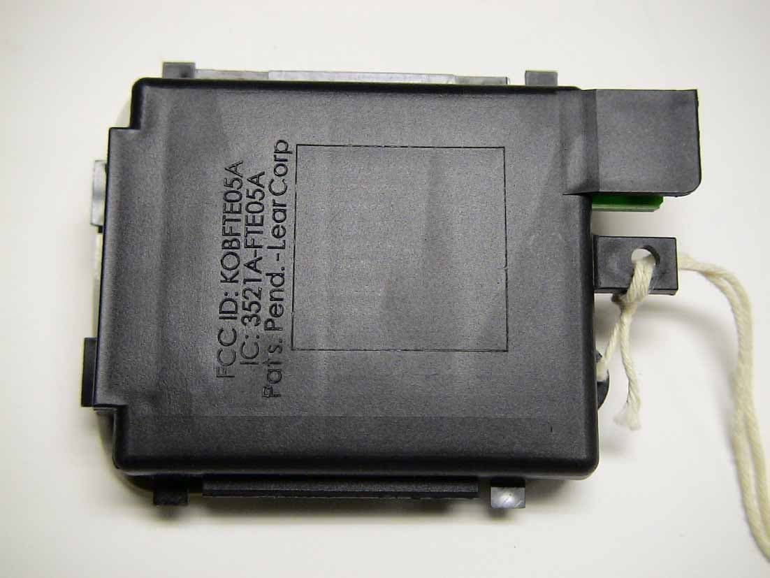
Click to zoom
Application Details
- Equipment Class
- DSC - Part 15 Security/Remote Control Transmitter
- Date of Grant
- Dec 18, 2005
- Application Purpose
- Original Equipment
- Date of Application
- Dec 18, 2005
- Equipment Note
- Multi-Frequency Transmitter
- Frequency Range
- 390.00000000 - 390.00000000
- Company
- Lear Corporation
- Country
- United States
Documents & Files
Document Text
Text extracted from the exhibit documents filed with the FCC. Open a document above to read the original.
Users Manual
LEAR Car2U ™ LEAR Car2U ™ Owner’s Guide Version 3.3 Page 1 12/2/2005 Lear Car2U Transmitter The Lear Universal Garage Door Opener (LEAR Car2U ™) is a universal transmitter and can replace up to three different remote control transmitter units used to operate the following types of devices: xGarage Door Opener xSecurity Devices xHome Lighting Systems Additional Lear Car2U ™ information can be found on the internet at www.learcar2U.com or by calling 1-866-57Car2U. Types of Garage Door Openers (Fixed Code and Rolling Code) LEAR Car2U ™ has the capability of programming rolling code and fixed code garage door openers: xRolling code garage door openers are used for garage doors produced after 1996 and are code protected. Rolling code means the coded signal is changed every time your remote control garage door opener is used. xFixed code garage door openers are used for garage doors produced prior to 1996. Fixed code uses the same coded signal every time, which is manually programmed by setting DIP switches for a unique personal code. If you do not know if your garage door opener is a rolling code or fixed code device, open your garage door opener’s remote control battery cover. If a panel of DIP switches is present as shown in the typical remote device shown below, your garage door opener is a fixed code device. If not, your garage door opener is a rolling code device. LEAR Car2U ™ LEAR Car2U ™ Owner’s Guide Version 3.3 Page 2 12/2/2005 Programming the LEAR Car2U ™ Transmitter Depending on your garage door opener manufacturer, LEAR Car2U ™ provides two easy ways to program your garage door opener. 1. Rolling Code Garage Door Openers: If your garage door opener is a rolling code device and do not have a row of dip switches use the “Programming Rolling Code Garage Door Opener” procedure on page 4. 2. Fixed Code Garage Door Opener: If your garage door opener is a fixed code device and has a row of dip switches use the “Programming Fixed Code Garage Door Opener” procedure on page 6. CAUTION xDo not use the LEAR Car2U ™ Transmitter with any garage door opener that does not have a “stop and reverse” feature. This includes any garage door opener model manufactured before April 1, 1982. xRead the instructions completely before attempting to program the LEAR Car2U ™ transmitter. Because of the steps involved, it may be helpful to have another person assist you in programming the transmitter. xBe sure to keep the original remote control transmitter for use in other vehicles as well as for future LEAR Car2U ™ programming. You only need it for fixed code device programming. It is also recommended that upon the sale or lease termination of the vehicle, the programmed LEAR Car2U ™ buttons should be erased for security reasons. Refer to “Erasing LEAR Car2U ™ Buttons” or for assistance, contact LEAR Car2U ™ at 1-866-57Car2U. xMake sure that people and objects are clear of the garage door opener or security device you are programming. When programming a garage door, it is advised to park outside the garage. PROGRAMING CONSIDERATIONS: Read the instructions completely before attempting to program Car2U. The following items may assist you in programming the system: oA ladder oA screwdriver oA writing pad and a pencil or pen It may be helpful but is not required to have an additional person available when programming Car2U. Retain the original transmitter for use in other vehicles as well as for future programming procedures (i.e. new Car2U-equipped vehicle purchase). Upon the sale of the vehicle, it is recommended that the programmed Car2U buttons should be erased for security reasons (refer to “Erase Car2U Settings”). Repeat the programming steps for each garage door opener you wish to program up to a maximum of three. CAUTION Programming the Rolling Code Garage Door Opener involves time-sensitive actions. Read the ENTIRE procedure prior to beginning so you will know which actions are time- sensitive. If you do not follow the time-sensitive actions, the device will time out and you will have to repeat the procedure. Make sure that your key is ON and engine OFF while programming the transmitter. LEAR Car2U ™ LEAR Car2U ™ Owner’s Guide Version 3.3 Page 3 12/2/2005 Programming Rolling Code Garage Door Opener or Device 1. Firmly PRESS the outer two LEAR Car2U ™ buttons for one — two seconds and immediately release them. 2. Go to the garage. Locate the garage door motor head and Press and Release its “learn” button. You may need a ladder to reach the unit and you may need to remove the unit’s cover to locate the “learn” button. After pressing the “learn” Button you have 10 to 30 seconds to complete Step 3 depending on your garage control unit If you cannot locate the “learn” button, refer to the Owner’s Guide of your garage door opener or call 1-866- 57Car2U. 3. Return to your vehicle, Press and HOLD the Car2U Button you would like to use to control the garage door. You may need to hold the button from 5 to 20 seconds during which time the selected button indicator light will blink slowly. Once the garage door begins to move immediately (within 1 second) release the button. The indicator light will blink rapidly until programming is complete Press and release the button again. The garage door should move confirming that programming is successful and complete. Press ANY one of the three LEAR Car2U ™ buttons to assign the rolling code to the garage door opener. “Learn” Button on the Garage Door opener motor head LEAR Car2U ™ LEAR Car2U ™ Owner’s Guide Version 3.3 Page 4 12/2/2005 4. To program another rolling code device such as an additional garage door opener, a security device, or home lighting, repeat steps 1 – 3 substituting a different function button in Step 3 than what you used for the garage door opener. For example, you could assign the left-most button to the garage door, the center button to a security device, and the right-most button to another garage door opener. To program another button with a f…
Text truncated - open the document above for the full version.
Attestation Statements
Re: Certification for Lear Transmitter Model(s): L0070144 FCC ID: KOBFTE05A IC: 3521A-FTE05A POWER OF ATTORNEY A letter granting Valdis V. Liepa the Power of Attorney is on file and can be provided when so requested. Re: Certification for Lear Transmitter Model(s): L0070144 FCC ID: KOBFTE05A IC: 3521A-FTE05A REQUEST FOR CONFIDENTIALITY Pursuant to 47 CRF 0.459, Lear requests that a part of the subject application be held confidential. This comprises Exhibits (5) Schematics (10) Parts List (Part of Exhibit only) Lear has spent substantial effort in developing this product and it is one of the first of its kind in industry. Having the subject information easily available to "competition" would negate the advantage they have achieved by developing this product. Not protecting the details of the design will result in financial hardship. If there are any questions regarding this request, please contact me at the above address or call 734-483-4211, fax 734-647-2106 or e-mail [email protected]. Sincerely, Valdis V. Liepa Research Scientist University of Michigan December 10, 2005 Re: Certification for Lear Transmitter Model(s): L0070144 FCC ID: KOBFTE05A IC: 3521A-FTE05A STATEMENT OF MODIFICATIONS There were no modifications made to the DUT by this test laboratory. However, during product development this laboratory was used by the applicant to determine correct output power levels for the device over all operating frequencies. (Also see Section 3.1 of the attached Test Report). _____________________ Valdis V. Liepa Research Scientist Re: Certification for Lear Transmitter Model(s): L0070144 FCC ID: KOBFTE05A IC: 3521A-FTE05A GENERAL PRODUCT INFORMATION The device, for which certification is pursued, has been designed by: Lear Corporation 5200 Auto Club Drive Dearborn, MI 48126 Tom Tang Tel: 313-593 - 9934 Fax: 313-593-9526 It will be manufactured by: EPIC Technologies 200 East Bluegrass Dr. Norwalk, OH 44857 Tom Tang Tel: 313-593 - 9934 Fax: 313-593-9526 Canadian Contact: Tom Odell 1908 Colonel Sam Drive Oshawa, ON L1H 8P7 Tel: (905) 644 - 7103
Attestation Statements
Re: Certification for Lear Transmitter Model(s): L0070144 FCC ID: KOBFTE05A IC: 3521A-FTE05A REQUEST FOR SHORT-TERM CONFIDENTIALITY Lear requests that a part of the subject application be held short-term confidential. This comprises Exhibit(s) (1) Internal Photos (3) External Photos (4) Block Diagram (7) Test Setup Photos (8) User’s Manual (9) Internal Photos (12) Description of Operation (13) Cover Letters The device in question will not be available to the consumer until the 2007/2008 automotive model year. Thus, Lear requests that the above exhibits not be made public at this time. Lear will continue to request the short-term confidentiality every 45 day period, up to 180 days from the date of grant, as necessary prior to release of the device. If there are any questions regarding this request, please contact me at the above address or call 734-483-4211, fax 734-647-2106 or e-mail [email protected]. Sincerely, Valdis V. Liepa Research Scientist
Block Diagram
5200 Auto Club Dr. Dearborn, Michigan 48126-9982 (313) 593-9000 Date: December 1, 2005 RE: Lear Universal Transmitter Model # L0070144 FCC ID: KOBFTE05A (Proposed) IC: 3521A-FTE05A (Proposed) Block Circuit Diagram Transmit Functions The circuit is actuated when one of the three switches is depressed. The switch operation powers the module and the 20MHz crystal oscillator clock circuit of the microcontroller turns on. The microcontroller generates data internally based on the timing of the clock oscillator. The microcontroller also configures the frequency synthesizer/PLL IC for proper RF data frequency operation. The frequency synthesizer/PLL IC shares the same 20MHz clock source as the microcontroller. The data is outputted from the microcontroller to the RF amplifier, switching power on and off to the amplifier generating an AM transmission signal. The RF amplifier radiates out through a PCB trace monopole antenna.
Cover Letter(s)
December 10, 2005 Federal Communications Commission Equipment Approval Services P.O. Box 358315 Pittsburgh, PA 15251-5315 Re: Certification for Lear Transmitter Model(s): L0070144 FCC ID: KOBFTE05A IC: 3521A-FTE05A Please find enclosed application materials for certification of Lear L0070144 Transmitter. We tested it and found it to comply with FCC Part 15. If there are any questions regarding the application or testing performed, please contact me at the above address or call 734-483-4211, fax 734-647-2106, or e-mail [email protected]. Sincerely, Valdis V. Liepa Research Scientist December 10, 2005 Certification and Engineering Bureau Industry Canada 3701 Carling Avenue, Bldg. 94 Ottawa, Ontario K2H 8S2 Re: Certification for Lear Transmitter Model(s): L0070144 FCC ID: KOBFTE05A IC: 3521A-FTE05A Please find enclosed application materials for certification of Lear L0070144 Transmitter. We tested the device and found it to comply with RSS-GEN/102/210. The product is identified by: IC: 3521A-FTE05A If there are any questions, suggestions, etc., regarding the application or testing performed, please contact me at the above address or call 734-483-4211, fax 734-647- 2106; e-mail: [email protected]. Sincerely, Valdis V. Liepa Research Scientist
Cover Letter(s)
The following FCC correspondence was used in determining the most appropriate set of frequencies and duty cycles required for demonstrating DUT compliance. While the garage door opener in question is not a Learned Mode Transmitter, it performs a similar function and its testing is thus guided to some extent by the procedure used in testing such a device. Currently Display Inquiry Tracking Number: 642164 Contact Information: Customer First Name: Valdis Customer Last Name: Liepa Telephone Number: 734 483 4211 Extension: E-mail Address: [email protected] Address: Line 1:N/A Line 2: P.O. Box: City:N/A State: Zip Code: Country: Inquiry Details: First Inquiry Category: Radio Service Rules Second Inquiry Category: Part 15 Intentional Radiators Third Inquiry Category: Remote Control Devices We are in the process of testing and preparing submission for certification of a Lear Corporation transmitter. This transmitter is designed to emulate existing garage door / gate control transmitters and have the ability to transmit on multiple user-selected frequencies. This is not a learning transmitter, as the user selects a protocol (frequency and code) from an available pre-defined set based on make, model, or more detailed information about their door/gate opener. Attached is a more detailed letter and test proposal. We hope to make this application through a TCB. Please review. ---Reply from Customer on 07/24/2005--- 1) We have proposed the 30%, 50%, and 80% duty cycle tests based on the test procedure used for learning garage door transmitters. Since this device performs the same function we chose to test it in a similar manner. Like the learning transmitters, it has an internal attenuator that adjusts the output level as a function of duty cycle. However, from the comments above would the FCC find it sufficient that the device be tested with only the worst case duty factor (device on for the longest period of time / 100ms at the proposed test frequencies)? 2) Yes, the bandwidth will be aggregated when multiple frequencies are transmitted during the same button press. 3) Is it satisfactory that a TCB review this application? ---Reply from Customer on 08/02/2005--- If you can, please respond to the relpy above. thank you Response: 1). Test worst case duty cycle. The dip settings shown in Table 2 do not produce maximum on time. Please explain. 2). Please be aware that when computing bandwidths you must use an aggregate of all bandwidths of frequencies used when activated. Follow the procedure in paragraph 3 of the Public Notice on learned mode or trainable transmitters concerning duty cycle. Be sure to include the test of the worst case duty cycle. You may review this application. Page 1 of 1OET Inquiry System Reply to OET Response, Inquiry Tracking Number 642164 12/9/2005https://gullfoss2.fcc.gov/prod/oet/cf/kdb/forms/ReplyToResponse.cfm PUBLIC NOTICE Federal Communications Commission 445 12 th St., S.W. Washington, D.C. 20554 News Media Information 202 / 418-0500 Internet: http://www.fcc.gov TTY: 1-888-835-5322 DA 02-2850 October 28, 2002 FCC Clarifies Equipment Certification Procedures for ”Learned Mode” or “Trainable” Transmitters This Public Notice is intended to clarify the information that should be provided in an application for certification of “Learned Mode” or “Trainable” transmitters. “Learned Mode” or “Trainable” transmitters are typically sold as universal replacements or duplicates for garage door opener controls, keyless entry systems, security alarm systems, remote switches, and similar types of radio controlled devices. These transmitters are designed to recognize and replicate the operating frequency, duty cycle and coding scheme of the targeted radio system. They accomplish this only when operated in very close proximity to a system’s receiver in order to prevent use for theft. These devices are subject to certification to ensure compliance with the technical requirements in Part 15 of the FCC Rules (47 CFR Part 15). A significant number of the applications for certification of “Learned Mode” or “Trainable” transmitters have been incomplete or incorrect. For example, applicants did not properly specify the range of operating frequencies. In some cases the devices were found to be capable of transmitting in restricted frequency bands in violation of 47 CFR 15.205, which could potentially cause interference to radio services used for public safety. Applicants often did not determine the duty cycle properly, or apply it correctly when calculating the maximum field strength. The following guidance is provided to ensure that future applications for certification of such equipment are complete and correct: 1. The application for certification must include a complete description of the operation of the devices, including the process it uses to learn and replicate the characteristics of the target system. The application should state how the learning process is constrained so as to minimize any potential for abuse. The statement must be consistent with the user manual instructions on replicating the frequencies and code of the target transmitter. In addition, it must provide assurances that there are no means (either software or hardware) for the end user to change the operating parameters from those reported in the application. A statement should also be included in the application that the Commission will be notified, in writing, of any changes in the software or programming of the device that could affect the device’s RF characteristics. 2. The test report must clearly state the specific frequencies or range of frequencies over which the transmitter is intended to operate. Test results must show that the transmitter operates only on the intended frequencies and is incapable of operating in the restricted frequency bands, as required by 47 CFR 15.205 and 15.209. If the device is designed to learn over a range of frequencies, the test report must include measurements that verify that the devi…
Text truncated - open the document above for the full version.
Cover Letter(s)
December 10, 2005 American Telecommunications Certification Body, Inc. 6731 Whittier Avenue Suite C110 McLean, VA 22101 RE: Certification Application FCC ID: KOBFTE05A IC: 3521A-FTE05A Model(s): L0070144 Please find enclosed application materials for certification of Lear L0070144 multi- frequency transmitter. Note: 1) portions of this submittal are filed Confidential 2) a list of the modifications made is provided in Attestations. If there are any questions regarding the application or testing performed, please contact me at the above address or call 734-483-4211, fax 734-647-2106, or e-mail [email protected]. Sincerely, Valdis V. Liepa Research Scientist
Cover Letter(s)
December 15, 2005 RE: Lear Corporation FCC ID: KOBFTE05A The following is in response to the comments made on the above referenced application. 1.) In the test report the timing plots pages 10 and 16 have plots that the Marker Delta is unreadable. Please correct the test report so the data is readable. Our apologies. We have scanned the hardcopies of the plots referenced and updated the test report.
Cover Letter(s)
American Telecommunications Certification Body Inc. 6731 Whittier Ave, McLean, VA 22101 December 14, 2005 RE: Lear Corporation FCC ID: KOBFTE05A I have a few comments on this Application. 1.) In the test report the timing plots pages 10 and 16 have plots that the Marker Delta is unreadable. Please correct the test report so the data is readable. Thank you, Douglas E. Noble Examining Engineer mailto: [email protected] The items indicated above must be submitted before processing can continue on the above referenced application. Failure to provide the requested information may result in application termination. Correspondence should be considered part of the permanent submission and may be viewed from the Internet after a Grant of Equipment Authorization is issued. Please do not respond to this correspondence using the email reply button. In order for your response to be processed expeditiously, you must submit your documents through the AmericanTCB.com website. Also, please note that partial responses increase processing time and should not be submitted. Any questions about the content of this correspondence should be directed to the sender.
Cover Letter(s)
Re: Certification for Lear Transmitter Model(s): L0070144 FCC ID: KOBFTE05A IC: 3521A-FTE05A REQUEST FOR SHORT-TERM CONFIDENTIALITY Lear requests that a part of the subject application be held short-term confidential. This comprises Exhibit(s) (1) Internal Photos (3) External Photos (4) Block Diagram (7) Test Setup Photos (8) User’s Manual (9) Internal Photos (12) Description of Operation The device in question will not be available to the consumer until the 2007/2008 automotive model year. Thus, Lear requests that the above exhibits not be made public at this time. Lear will continue to request the short-term confidentiality every 45 day period, up to 180 days from the date of grant, as necessary prior to release of the device. If there are any questions regarding this request, please contact me at the above address or call 734-483-4211, fax 734-647-2106 or e-mail [email protected]. Sincerely, Valdis V. Liepa Research Scientist
Cover Letter(s)
Re: Certification for Lear Transmitter Model(s): L0070144 FCC ID: KOBFTE05A IC: 3521A-FTE05A REQUEST FOR CONFIDENTIALITY Pursuant to 47 CRF 0.459, Lear requests that a part of the subject application be held confidential. This comprises Exhibits (5) Schematics (10) Parts List (Part of Exhibit only) (11) Description of Operation (11) Response to Comments Lear has spent substantial effort in developing this product and it is one of the first of its kind in industry. Having the subject information easily available to "competition" would negate the advantage they have achieved by developing this product. Not protecting the details of the design will result in financial hardship. If there are any questions regarding this request, please contact me at the above address or call 734-483-4211, fax 734-647-2106 or e-mail [email protected]. Sincerely, Valdis V. Liepa Research Scientist University of Michigan
Cover Letter(s)
Re: Certification for Lear Transmitter Model(s): L0070144 FCC ID: KOBFTE05A IC: 3521A-FTE05A REQUEST FOR SHORT-TERM CONFIDENTIALITY Lear requests that a part of the subject application be held short-term confidential. This comprises Exhibit(s) (1) Internal Photos (3) External Photos (4) Block Diagram (7) Test Setup Photos (8) User’s Manual (9) Internal Photos (13) Cover Letters The device in question will not be available to the consumer until the 2007/2008 automotive model year. Thus, Lear requests that the above exhibits not be made public at this time. Lear will continue to request the short-term confidentiality every 45 day period, up to 180 days from the date of grant, as necessary prior to release of the device. If there are any questions regarding this request, please contact me at the above address or call 734-483-4211, fax 734-647-2106 or e-mail [email protected]. Sincerely, Valdis V. Liepa Research Scientist
Cover Letter(s)
Re: Certification for Lear Transmitter Model(s): L0070144 FCC ID: KOBFTE05A IC: 3521A-FTE05A REQUEST FOR SHORT-TERM CONFIDENTIALITY Lear requests that a part of the subject application be held short-term confidential. This comprises Exhibit(s) (1) Internal Photos (3) External Photos (4) Block Diagram (7) Test Setup Photos (8) User’s Manual (9) Internal Photos The device in question will not be available to the consumer until the 2007/2008 automotive model year. Thus, Lear requests that the above exhibits not be made public at this time. Lear will continue to request the short-term confidentiality every 45 day period, up to 180 days from the date of grant, as necessary prior to release of the device. If there are any questions regarding this request, please contact me at the above address or call 734-483-4211, fax 734-647-2106 or e-mail [email protected]. Sincerely, Valdis V. Liepa Research Scientist
External Photos
DUT with Harness DUT (top) DUT (bottom)
ID Label/Location Info
5200 Auto Club Dr. Dearborn, Michigan 48126-9982 (313) 593-9000 Date: December 1, 2005 RE: Lear Universal Transmitter Model # L0070144 FCC ID: KOBFTE05A (Proposed) IC: 3521A-FTE05A (Proposed) FCC/IC Label
Internal Photos
DUT apart (top) DUT apart (bottom) PCB (top) PCB (bottom) RF Shield (removed) RF Shield (removed)
Test Report
University of Michigan Radiation Laboratory FCC Part 15, IC RSS-210/Gen - Test Report No. 415031-268 Page 1 of 22 The University of Michigan Radiation Laboratory 3228 EECS Building Ann Arbor, MI 48109-2122 Tel: (734) 764-0500 Measured Radio Frequency Emissions From Lear Corporation Car2U Transmitter Model(s): L0070144 Report No. 415031-268 December 9, 2005 Copyright © 2005 For: Lear Corporation 5200 Auto Club Dr. Dearborn, MI 48126-9982 Contact: Tom Tang Tel: 313-593 - 9934 Fax: 313-593-9526 PO: Verbal Tests supervised by: Measurements made by: Report approved by: _____________________ Valdis V. Liepa Valdis V. Liepa Joseph D. Brunett Research Scientist Summary Tests for compliance with FCC Regulations Part 15, Subpart C, and Industry Canada RSS-210/Gen, were performed on Lear Corporation model L0070144. This device is subject to the Rules and Regulations as a Transmitter. In testing completed on December 6, 2005, the device tested in the worst case met the allowed FCC specifications for radiated emissions by 1.0 dB (see p. 7-9). Besides harmonics, there were no other significant spurious emissions found; emissions from digital circuitry were negligible. The conducted emission tests do not apply, since the device is powered from a 12 VDC battery. University of Michigan Radiation Laboratory FCC Part 15, IC RSS-210/Gen - Test Report No. 415031-268 Page 2 of 22 1. Introduction Lear Corporation model L0070144 was tested for compliance with FCC Regulations, Part 15, adopted under Docket 87-389, April 18, 1989, and with Industry Canada RSS-210, Issue 6, September 2005. The tests were performed at the University of Michigan Radiation Laboratory Willow Run Test Range following the procedures described in ANSI C63.4-2003 "Methods of Measurement of Radio-Noise Emissions from Low-Voltage Electrical and Electronic Equipment in the Range of 9 kHz to 40 GHz". The Site description and attenuation characteristics of the Open Site facility are on file with FCC Laboratory, Columbia, Maryland (FCC Reg. No: 91050) and with Industry Canada, Ottawa, ON (File Ref. No: IC 2057). 2. Test Procedure and Equipment Used The pertinent test equipment commonly used in our facility for measurements is listed in Table 2.1 below. The middle column identifies the specific equipment used in these tests. Table 2.1 Test Equipment. Test Instrument Eqpt. Used Manufacturer/Model Spectrum Analyzer (0.1-1500 MHz) Hewlett-Packard, 182T/8558B Spectrum Analyzer (9kHz-22GHz) X Hewlett-Packard 8593A SN: 3107A01358 Spectrum Analyzer (9kHz-26GHz) X Hewlett-Packard 8593E, SN: 3412A01131 Spectrum Analyzer (9kHz-26GHz) Hewlett-Packard 8563E, SN: 3310A01174 Spectrum Analyzer (9kHz-40GHz) Hewlett-Packard 8564E, SN: 3745A01031 Power Meter Hewlett-Packard, 432A Power Meter Anritsu, ML4803A/MP Harmonic Mixer (26-40 GHz) Hewlett-Packard 11970A, SN: 3003A08327 Harmonic Mixer (40-60 GHz) Hewlett-Packard 11970U, SN: 2332A00500 Harmonic Mixer (75-110 GHz) Hewlett-Packard 11970W, SN: 2521A00179 Harmonic Mixer (140-220 GHz) Pacific Millimeter Prod., GMA, SN: 26 S-Band Std. Gain Horn S/A, Model SGH-2.6 C-Band Std. Gain Horn University of Michigan, NRL design XN-Band Std. Gain Horn University of Michigan, NRL design X-Band Std. Gain Horn S/A, Model 12-8.2 X-band horn (8.2- 12.4 GHz) Narda 640 X-band horn (8.2- 12.4 GHz) Scientific Atlanta , 12-8.2, SN: 730 K-band horn (18-26.5 GHz) FXR, Inc., K638KF Ka-band horn (26.5-40 GHz) FXR, Inc., U638A U-band horn (40-60 GHz) Custom Microwave, HO19 W-band horn(75-110 GHz) Custom Microwave, HO10 G-band horn (140-220 GHz) Custom Microwave, HO5R Bicone Antenna (30-250 MHz) X University of Michigan, RLBC-1 Bicone Antenna (200-1000 MHz) X University of Michigan, RLBC-2 Dipole Antenna Set (30-1000 MHz) X University of Michigan, RLDP-1,-2,-3 Dipole Antenna Set (30-1000 MHz) EMCO 2131C, SN: 992 Active Rod Antenna (30 Hz-50 MHz) EMCO 3301B, SN: 3223 Active Loop Antenna (30 Hz-50 MHz) EMCO 6502, SN:2855 Ridge-horn Antenna (300-5000 MHz) X University of Michigan Amplifier (5-1000 MHz) X Avantak, A11-1, A25-1S Amplifier (5-4500 MHz) X Avantak Amplifier (4.5-13 GHz) Avantek, AFT-12665 Amplifier (6-16 GHz) Trek Amplifier (16-26 GHz) Avantek LISN Box University of Michigan Signal Generator Hewlett-Packard 8657B University of Michigan Radiation Laboratory FCC Part 15, IC RSS-210/Gen - Test Report No. 415031-268 Page 3 of 22 3. Configuration and Identification of Device Under Test The DUT is a multi-frequency (8 frequencies total: 288MHz, 300MHz, 303MHz, 310MHz, 315MHz, 318MHz, 372MHz, and 390MHz) transmitter, 3 x 0.5 x 3 inches in size, designed to emulate existing garage door openers within a pre-defined list of manufacturers and model numbers. This transmitter has pre-programmed protocols that are selectable by the user based upon the manufacturer and model number of the transmitter they are trying to emulate. There are three buttons on the device so that the user may program a separate protocol to each button. There exist only 2 protocols (transmitted at 390MHz and 315MHz) wherein more than a single frequency is used during a single button press. The output power of the DUT is internally adjusted according to the RF frequency and data transmitted. Duty factors are calculated in software for all fixed code transmissions. For rolling code transmissions, the duty factor is computed for the worst case maximum on time. The antenna is a trace on the PCB. The DUT was designed and manufactured by Lear Corporation, 5200 Auto Club Dr., Dearborn, MI 48126-9982. It is identified as: Lear Corporation Transmitter Model: L0070144 FCC ID: KOBFTE05A IC: 3521A-FTE05A Since the DUT is capable of transmitting a large number of different protocols over 8 different frequencies, the following test procedure has been followed. The lowest, middle, and highest frequencies have been tested for the worst case duty cycle (least on time in 100 ms window). This includes the worst case condition of the two dual-frequency protocols, and follows the recommenda…
Text truncated - open the document above for the full version.
Test Report
University of Michigan Radiation Laboratory FCC Part 15, IC RSS-210/Gen - Test Report No. 415031-268 rev. 1 Page 1 of 22 The University of Michigan Radiation Laboratory 3228 EECS Building Ann Arbor, MI 48109-2122 Tel: (734) 764-0500 Measured Radio Frequency Emissions From Lear Corporation Car2U Transmitter Model(s): L0070144 Report No. 415031-268 rev. 1 February 17, 2006 Copyright © 2006 For: Lear Corporation 5200 Auto Club Dr. Dearborn, MI 48126-9982 Contact: Tom Tang Tel: 313-593 - 9934 Fax: 313-593-9526 PO: Verbal Tests su…
Text truncated - open the document above for the full version.
Contact Information
Applicant
Kristof von Czarnowski(RF Engineer)
Technical Contact
University of Michigan EECSValdis Liepa
[email protected]734-483-4211
1301 Beal Avenue · Ann Arbor, Michigan · United States
Test Firm
University of MichiganValdis Liepa
Technical Specifications
| # | Rule Parts | Frequency Range | Power Output |
|---|---|---|---|
| 8 | 15.231 | 390 MHz - 390 MHz | - |
Other Applications from Lear Corporation
KOBJXF23B
Jul 20, 2026RKE Transmitter with UWB
Equipment Class
DSC - Part 15 Security/Remote Control Transmitter
KOBJXF23A
Sep 26, 2023RKE Transmitter with UWB
Equipment Class
DSC - Part 15 Security/Remote Control Transmitter
KOBHT13BTPM
Oct 15, 2012Security/Remote Control Transmitter
Equipment Class
DSC - Part 15 Security/Remote Control TransmitterKOBATA12A
Jun 20, 2012Remote keyless entry / Remote start
Equipment Class
DSC - Part 15 Security/Remote Control Transmitter
KOBGTE12A
Apr 20, 2012Car2U System TX
Equipment Class
DSC - Part 15 Security/Remote Control Transmitter