KOBLEAR1XTCar Keyless Entry TX
Lear Corporation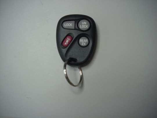
Click to zoom
Application Details
- Equipment Class
- DSC - Part 15 Security/Remote Control Transmitter
- Date of Grant
- Feb 07, 2000
- Application Purpose
- Original Equipment
- Date of Application
- Nov 09, 1999
- Equipment Note
- Car Keyless Entry TX
- Frequency Range
- 315.00000000 - 315.00000000
- Company
- Lear Corporation
- Country
- United States
Documents & Files
Document Text
Text extracted from the exhibit documents filed with the FCC. Open a document above to read the original.
Users Manual
5200 Auto Club Dr. Dearborn, Michigan 48126-9982 (313) 593-9000 Re: Certification for Lear Corporation FCC ID: KOBLEAR1XT The following statement will be printed in the User’s Instruction Manual This device complies with Part 15 of the FCC Rules and with RSS-210 Of the Industry Canada. Operation is subject to the following two conditions: (1) This device may not cause harmful interference, and (2) This device must accept any interference received, including interference that may cause undesired operation. WARNING: Changes or modifications not expressively approved by the party responsible for compliance could void the user’s authority to operate the equipment.
Block Diagram
5200 Auto Club Dr. Dearborn, Michigan 48126-9982 (313) 593-9000 Re: Certification for Lear Corporation Transmitter, Model RLC-X, RLC-C+ FCC ID: KOBLEAR1XT CANADA: Block Circuit Diagram The circuit is actuated when one of the three or four switches is depressed. The switch operation “wake’s up” the encoder, and the internal clock circuit turns on. The encoder generates data internally based on the timing of the clock oscillator. The data is outputted from the encoder to the 315 MHz, SAWR (Surface Acoustic Wave Resonator) stabilized oscillator. This oscillator is then turned on and off at the data rate outputted from the encoder. The oscillator radiates out through a PCB trace antenna. 315 315 MHz SAWR oscillator Encoder With integratedclock ill t Buttons PCB trace Antenna
External Photos
5200 Auto Club Dr. Dearborn, Michigan 48126-9982 (313) 593-9000 Re: Certification for Lear Corporation Transmitter, Model RLC-X, RLC-C+ FCC ID: KOBLEAR1XT CANADA: PICTURES Case Top 5200 Auto Club Dr. Dearborn, Michigan 48126-9982 (313) 593-9000 Re: Certification for Lear Corporation Transmitter, Model RLC-X, RLC-C+ FCC ID: KOBLEAR1XT CANADA: PICTURES (cont) Case Bottom
ID Label/Location Info
5200 Auto Club Dr. Dearborn, Michigan 48126-9982 (313) 593-9000 Re: Certification for Lear Corporation Transmitter, Model RLC-X, RLC-C+ FCC ID: KOBLEAR1XT CANADA: FCC and IC ID LABEL and STATEMENT The following drawings outline the 7 different cosmetic versions of this transmitter. The internal PCB and components are the same between these versions. The label(s) below will be embossed on the outside and on the back of the plastic case of the transmitter. 5200 Auto Club Dr. Dearborn, Michigan 48126-9982 (313) 593-9000 Re: Certification for Lear Corporation Transmitter, Model RLC-X, RLC-C+ FCC ID: KOBLEAR1XT CANADA: FCC and IC ID LABEL and STATEMENT (cont) The following statement will be printed in the User’s Instruction Manual This device complies with Part 15 of the FCC Rules and with RSS-210 of the Industry Canada. Operation is subject to the following two conditions: (1) This device may not cause harmful interference, and (2) This device must accept any interference received, including interference that may cause undesired operation. 5200 Auto Club Dr. Dearborn, Michigan 48126-9982 (313) 593-9000 Re: Certification for Lear Corporation Transmitter, Model RLC-X, RLC-C+ FCC ID: KOBLEAR1XT CANADA: WARNING: Changes or modifications not expressively approved by the party responsible for compliance could void the user’s authority to operate the equipment.
ID Label/Location Info
5200 Auto Club Dr. Dearborn, Michigan 48126-9982 (313) 593-9000 Re: Certification for Lear Corporation Transmitter, Model RLC-X, RLC-C+ FCC ID: KOBLEAR1XT CANADA: FCC and IC ID LABEL and STATEMENT The following drawings outline the 7 different cosmetic versions of this transmitter. The internal PCB and components are the same between these versions. The label(s) below will be embossed on the outside and on the back of the plastic case of the transmitter. 5200 Auto Club Dr. Dearborn, Michigan 48126-9982 (313) 593-9000 Re: Certification for Lear Corporation Transmitter, Model RLC-X, RLC-C+ FCC ID: KOBLEAR1XT CANADA: FCC and IC ID LABEL and STATEMENT (cont) The following statement will be printed in the User’s Instruction Manual This device complies with Part 15 of the FCC Rules and with RSS-210 of the Industry Canada. Operation is subject to the following two conditions: (1) This device may not cause harmful interference, and (2) This device must accept any interference received, including interference that may cause undesired operation. 5200 Auto Club Dr. Dearborn, Michigan 48126-9982 (313) 593-9000 Re: Certification for Lear Corporation Transmitter, Model RLC-X, RLC-C+ FCC ID: KOBLEAR1XT CANADA: WARNING: Changes or modifications not expressively approved by the party responsible for compliance could void the user’s authority to operate the equipment.
Internal Photos
5200 Auto Club Dr. Dearborn, Michigan 48126-9982 (313) 593-9000 Re: Certification for Lear Corporation Transmitter, Model RLC-X, RLC-C+ FCC ID: KOBLEAR1XT CANADA: PICTURES Murata version 5200 Auto Club Dr. Dearborn, Michigan 48126-9982 (313) 593-9000 Re: Certification for Lear Corporation Transmitter, Model RLC-X, RLC-C+ FCC ID: KOBLEAR1XT CANADA: PICTURES (cont) Bottom side of Board
Operational Description
5200 Auto Club Dr. Dearborn, Michigan 48126-9982 (313) 593-9000 Re: Certification for Lear Corporation Transmitter, Model RLC-X, RLC-C+ FCC ID: KOBLEAR1XT CANADA: DESCRIPTION OF OPERATION GENERAL DESCRIPTION The product for which certification is pursued will be manufactured for GM Motor Company by Lear Corporation (formerly United Technologies Automotive) for automotive applications. This 315 MHz transmitter works in conjunction with a receiver that is mounted in the vehicle. The transmitter is a 3 volt, single cell battery operated fob type that is carried by the user. It is part of a keyless entry system and can be used to perform certain functions such as lock and unlock the driver and passenger doors, open the trunk, etc... depending on how the receiver module in the vehicle is programmed. There are seven versions of this transmitter. The only difference between these seven units are the number of buttons used, the printing on the buttons, and the GM/UTA part number stamped on the back. Electrically, all seven units are identical. The transmitter fob contains one 3 volt battery and a printed circuit board assembly. The two piece exterior housing is injection molded plastic, with the GM/UTA #, FCC ID #, and CANADA # stamped into the plastic. TECHNICAL DESCRIPTION When the buttons are depressed, the encoder IC will power up and generate the proper data code which can only be recognized by a matched receiver. The code is carried by 315 MHz carrier with AM OOK (on-off keying) modulation and radiated by a printed circuit board antenna. The data code is of a pulse width modulation format to express bits “0” and “1”. The data code period is controlled by the encoder clock, which is an RC oscillator type that is integrated into the encoder. The antenna is a PCB trace and is a mono-pole type. The 315 MHz transmit frequency is generated by a SAWR (Surface Acoustic Wave Resonator) stabilized, Colpits oscillator. Frequency tolerance is better than 315 MHz, +/- 150 kHz. NAME AND ADDRESS OF MANUFACTURER Lear Corporation (Formerly United Technologies Automotive) 5200 Auto Club Drive Dearborn, Michigan 48126 And 5100 West Waters Ave. Tampa, FL 33634
Test Report
1 Test Method: FCC Part 15 Subpart C Radiated Emissions Paragraph 15.231 Customer: Lear Job No. 8284-1 Test Sample: Pulsed RF Transmitter FCC ID: KOBLEAR1XT Model No.: RLC-X (RFM Version) Serial No. N/A Operating Mode: Continuously Transmitter 315 Mhz Signal Technician: Tom Schneider Date: October 27,1999 Notes: Test Distance: 3 Meters Detector: Peak Test Freq. Antenna Pol./Height EUT Orientation Meter Reading Correction Factor Corrected Reading Converted Reading Peak Limit Mhz(V/H)-MetersX / Y / Z dBuv dB dBuV/m uV/m uV/m 315H /1.0X83.7-3.780.010000.060000 315H / 1.0Y83.4-3.779.79660.560000 315H / 1.0Z79.8-3.776.16382.660000 315V / 2.0X63.5-3.759.8977.260000 315V / 1.3Y62.6-3.758.9881.060000 315V / 1.8Z67.4-3.763.71531.160000 630H / 1.3X51.53.054.5530.96000 630H / 1.3Y50.73.053.7484.26000 630H / 2.0Z 43.93.046.9221.36000 630V / 1.2X42.23.045.2182.06000 630V / 1.2Y44.23.047.2229.16000 630V / 1.0Z41.53.044.5167.96000 945H / 1.0X46.58.755.2575.46000 945H / 1.0Y43.38.752.0398.16000 945H / 1.0Z46.88.755.5595.76000 945V / 1.0X41.78.750.4331.16000 945V / 1.4Y42.68.751.3367.36000 945V / 1.0Z43.98.752.6426.66000 1260H / 1.4X46.4-5.540.9110.96000 1260H / 1.4Y51.6-5.546.1201.86000 1260H / 1.4Z49.9-5.544.4166.06000 1260V / 1.1X53.5-5.548.0251.26000 1260V / 1.1Y48.1-5.542.6134.96000 1260V / 1.3Z56.7-5.551.2363.16000 1575H / 1.7X49.5-4.345.2182.05000 1575H / 1.1Y56.6-4.352.3412.15000 1575H / 1.2Z46.7-4.342.4131.85000 1575V / 1.1X60.9-4.356.6676.15000 1575V /1.1Y50.4-4.346.1201.85000 1575V /1.2Z56.4-4.352.1402.75000 The frequency range was scanned from 30 Mhz to 3.1 Ghz. All emissions not recorded were more Than 10 dB below the specified limit. Emissions from the EUT do not exceed the specified limits. *=Noise Floor Measurements ( Minimum system sensitivity) 2 Test Method: FCC Part 15 Subpart C Radiated Emissions Paragraph 15.231 Customer: Lear Job No. 8284-1 Test Sample: Pulsed RF Transmitter FCC ID: KOBLEAR1XT Model No.: RLC-X (RFM Version) Serial No. N/A Operating Mode: Continuously Transmitter 315 Mhz Signal Technician: Tom Schneider Date: October 27,1999 Notes: Test Distance: 3 Meters Detector: Quasi-Peak Test Freq. Antenna Pol./Height EUT Orientation Meter Reading Correction Factor Corrected Reading Converted Reading Peak Limit Mhz(V/H)-MetersX / Y / Z dbuv DB dBuV/m uV/m uV/m 1890H /1.7X54.81.656.4660.76000 1890H / 1.4Y48.51.650.1319.96000 1890H /2.0Z56.81.658.4831.86000 1890V / 1.6X50.61.652.2407.46000 1890V / 1.4Y52.81.654.4524.86000 1890V / 1.9Z46.41.648.0251.26000 2205H / 1.8X52.9-1.151.8389.05000 2205H / 1.8Y51.8-1.150.7342.85000 2205H / 1.9Z55.5-1.154.4524.85000 2205V /1.1X50.0-1.148.9278.65000 2205V / 1.1Y51.6-1.150.5335.05000 2205V / 2.0Z54.0-1.152.9441.65000 2520H / 1.4X55.00.355.3582.16000 2520H / 1.4Y58.20.358.5841.46000 2520H / 2.0Z55.00.355.3582.16000 2520V / 1.3X51.30.351.6380.26000 2520V / 1.8Y54.00.354.3518.86000 2520V / 1.7Z58.80.359.1901.66000 2835H / 1.2X54.00.754.7543.35000 2835H / 1.4Y52.10.752.8436.55000 2835H / 2.6Z55.70.756.4660.75000 2835V / 1.9X45.80.746.5211.35000 2835V / 1.5Y52.50.753.2457.15000 2835V / 1.8Z54.70.755.4588.85000 3150H / 1.3X47.53.651.1358.96000 3150H / 1.4Y48.63.652.2407.46000 3150H / 2.2Z52.53.656.1638.36000 3150V / 1.6X45.33.648.9278.66000 3150V / 1.3Y47.03.650.6338.86000 3150V / 1.1Z44.33.647.9248.36000 The frequency range was scanned from 30 Mhz to 3.2 Ghz. All emissions not recorded were more Than 10 dB below the specified limit. Emissions from the EUT do not exceed the specified limits. *=Noise Floor Measurements ( Minimum system sensitivity) 3 Test Method: FCC Part 15 Subpart C Radiated Emissions Paragraph 15.231 Customer: Lear Job No. 8284-1 Test Sample: Pulsed RF Transmitter FCC ID: KOBLEAR1XT Model No.: RLC-X (RFM Version) Serial No. N/A Operating Mode: Continuously Transmitter 315 Mhz Signal Technician: Tom Schneider Date: October 27,1999 Notes: Test Distance: 3 Meters Duty Cycle: 31.6% Detector: Peak Duty Cycle Correction: -10 dB Test Freq. Antenna Pol./Height EUT Orientation Peak Reading Correction Factor Corrected Reading Converted Reading Average Limit Mhz(V/H)-MetersX / Y / Z dBuv DB dBuV/m uV/m uV/m 315H /1.0X80.0-10.070.03162.36000 315H / 1.0Y79.7-10.069.73054.96000 315H / 1.0Z76.1-10.066.12018.46000 315V / 2.0X59.8-10.049.8309.06000 315V / 1.3Y58.9-10.048.9278.66000 315V / 1.8Z63.7-10.053.7484.26000 630H / 1.3X54.5-10.044.5167.9600 630H / 1.3Y53.7-10.043.7153.1600 630H / 2.0Z46.9-10.036.970.0600 630V / 1.2X45.2-10.035.257.5600 630V / 1.2Y47.2-10.037.272.4600 630V / 1.0Z44.5-10.034.553.1600 945H / 1.0X55.2-10.045.2182.0600 945H / 1.0Y52.0-10.042.0125.9600 945H / 1.0Z55.5-10.045.5188.4600 945V / 1.0X50.4-10.040.4104.7600 945V / 1.4Y51.3-10.041.3116.1600 945V / 1.0Z52.6-10.042.6134.9600 1260H / 1.4X40.9-10.030.935.1600 1260H / 1.4Y46.1-10.036.163.8600 1260H / 1.4Z44.4-10.034.452.5600 1260V / 1.1X48.0-10.038.079.4600 1260V / 1.1Y42.6-10.032.642.7600 1260V / 1.3Z51.2-10.041.2114.8600 1575H / 1.7X45.2-10.035.257.5500 1575H / 1.1Y52.3-10.042.3130.3500 1575H / 1.2Z42.4-10.032.441.7500 1575V / 1.1X56.6-10.046.6213.8500 1575V /1.1Y46.1-10.036.163.8500 1575V /1.2Z52.1-10.042.1127.4500 The frequency range was scanned from 30 Mhz to 3.1 Ghz. All emissions not recorded were more Than 10 dB below the specified limit. Emissions from the EUT do not exceed the specified limits. *=Noise Floor Measurements ( Minimum system sensitivity) 4 Test Method: FCC Part 15 Subpart C Radiated Emissions Paragraph 15.231 Customer: Lear Job No. 8284-1 Test Sample: Pulsed RF Transmitter FCC ID: KOBLEAR1XT Model No.: RLC-X (RFM Version) Serial No. N/A Operating Mode: Continuously Transmitter 315 Mhz Signal Technician: Tom Schneider Date: October 27,1999 Notes: Test Distance: 3 Meters Duty Cycle: 10% Detector: Quasi-Peak Duty Cycle Correction: -20 dB Test Freq. Antenna Pol./Height EUT Orientation Peak Reading Correction Factor Corrected Reading Converted Reading Average Limit Mhz(V/H)-MetersX / Y / Z dBuv dB dBuV/m UV/m uV/m 1890H /1.7X56.4-10.046.4208.9600 1890H / 1.4Y…
Text truncated - open the document above for the full version.
Test Report
Test Report No. R-8284-1 FCC ID: KOBLEAR1XT APPLICANT Lear Corporation 5300 Auto Club Drive Dearborn, MI 48126 MANUFACTURER Lear Corporation 5100 West Waters Avenue Tampa, FL 33634 TEST SPECIFICATION: FCC Rules and Regulations Part 15, Subpart C, Para. 15.231 TEST PROCEDURE: ANSI C63.4:1992 TEST SAMPLE DESCRIPTION BRANDNAME: GM Motor Company MODEL: RLC-X TYPE: Pulsed RF Transmitter POWER REQUIREMENTS: 3 VDC derived from a CR2032 Battery FREQUENCY OF OPERATION: 315 MHz TESTS PERFORMED Para. 15.231(a), Radiated Emissions, Fundamental and Harmonics Para. 15.231(c), Occupied Bandwidth Duty Cycle Determination REPORT OF MEASUREMENTS Applicant: Lear Corporation Device:Pulsed RF Transmitter FCC ID: KOBLEAR1XT Applicable Rule Section:Part 15, Subpart C, Section 15.231 Test Report No. R-8284-1 FCC ID: KOBLEAR1XT REPORT OF MEASUREMENTS (continued) TEST RESULTS 15.231 (a) -The device is used as a transmitter for remote control purposes. 15.231 (a)(1) & -The transmitter is manually operated and ceases transmission within 5 15.231(2)seconds after deactivation. 15.231 (a)(3) -The transmitter does not perform periodic transmissions. 15.231 (a)(4)-The transmitter is employed for RC purposes involving Security. 15.231 (b) -The fundamental field strength did not exceed 6040 μV/M (Average) at a test distance of 3 meters. In addition, the requirements of section 15.35 for averaging pulsed emissions and for limiting peak emissions were met. The field strength of harmonic and spurious emissions did not exceed 604 μV/M (AVERAGE). 15.231 (c) -The device operates at 315 MHz. The bandwidth of emissions did not exceed 0.25% of the operating frequency (787.5 kHz). DETERMINATION OF FIELD STRENGTH LIMITS The field strength limits shown below are found in Section 15.231. Frequency Limit F1=2603750 =L1 Fo=315Lo F2=47012500 =L2 The formula below was utilized to determine the limits: Limit = L1 + [(Fo-F1)(L2-L1)/(F2-F1)] Solving yields: Fundamental Limit= 6,040 μV/M (AVERAGE) @ 3 Meters Harmonic Limit= 604 μV/M (AVERAGE) @ 3 Meters Test Report No. R-8284-1 FCC ID: KOBLEAR1XT REPORT OF MEASUREMENTS (continued) DETERMINATION OF DUTY CYCLE The following information was supplied by Lear Corp. Transmitter On Time=31.6 milliseconds (maximum- worst case in 100 ms) Transmitter Cycle Time => 110.0 milliseconds Transmitter Duty Cycle=31.6 % Duty Cycle=31.6 % Correction Factor = 20 log(0.316) =-10.0 dB SPECTRUM ANALYZER DESENSITIZATION CONSIDERATIONS Due to the nature of the emissions being measured, care was taken to ensure that the resolution bandwidth of the spectrum analyzer was adequate to provide accurate measurements. The following formula was utilized: Setting pulse desensitization equal to zero and utilizing the minimum observed pulse width of 200μs yields a minimum required bandwidth of 3333.3 Hz. FCC specified bandwidths of 100kHz and 1 MHz were utilized below and above 1 GHz, respectively. Test Report No. R-8284-1 FCC ID: KOBLEAR1XT REPORT OF MEASUREMENTS (continued) GENERAL NOTES 1. All readings were taken utilizing a peak detector function at a test distance of 3 meters. 2. The duty cycle was applied to the peak readings in order to determine the average value of the emissions. 3. All measurements were made with 3 VDC derived from a new CR2032 battery. 4. The frequency range was scanned from 30 MHz to 3.15 GHz. All emissions not reported were more than 20 dB below the specified limit. Test Report No. R-8284-1 FCC ID: KOBLEAR1XT EQUIPMENT LIST FCC PART 15 SUBPART C ENTypeManufacturerFrequency Range Model No.Cal Date Due Date 067Open Area Test SiteRetlif3 MeterRNY10/15/9710/15/00 128CDouble Ridge GuideEaton Corporation1 GHz - 18 GHz960019/16/999/16/00 133Broadband Pre-AmplifierElectro-Metrics10 kHz - 1 GHz, 26dBBPA-10006/22/996/22/00 141Spectrum AnalyzerHewlett Packard100 Hz - 40 GHz8566B9/20/993/20/00 141AGraphics PlotterHewlett PackardN/A7470A3/5/993/5/00 141BQuasi-Peak AdaptorHewlett Packard100 Hz - 1 GHz85650A9/20/993/20/00 206B6.0 dB AttenuatorTexscan0 - 1.0 GHzFP-50 - 6 dB6/22/996/22/00 523BiconilogElectro-Mechanics26 - 2000 MHz3142B10/22/984/22/00 543PreamplifierHewlett Packard1.0 GHz - 26.5 GHz8449B6/16/996/16/01 Test Report No. R-8284-1 FCC ID: KOBLEAR1XT FCC 15.231(b) RADIATED EMISSIONS, FUNDAMENTAL & SPURIOUS CASE (Please see separate e-file attachments named RedataRFM.doc and REdataMurata.doc) Test Report No. R-8284-1 FCC ID: KOBLEAR1XT FCC 15.231(c) OCCUPIED BANDWIDTH (Please see separate e-file attachment named Occbw.pdf)
Contact Information
Applicant
Kristof von Czarnowski(RF Engineer)
Technical Contact
RETLIF TESTING LABORATORIESTHOMAS J SCHNEIDER
[email protected]631-737*1500
795 MARCONI AVENUE · RONKONKOMA, New York · United States
Non-Technical Contact
RETLIF TESTING LABORATORIESMICHELLE TIRADO
[email protected]631-737-1500
Test Firm
Retlif Testing LaboratoriesMichael Bozza
Technical Specifications
| # | Rule Parts | Frequency Range | Power Output |
|---|---|---|---|
| 1 | 15C | 315 MHz - 315 MHz | - |
Other Applications from Lear Corporation
KOBJXF23B
Jul 20, 2026RKE Transmitter with UWB
Equipment Class
DSC - Part 15 Security/Remote Control Transmitter
KOBJXF23A
Sep 26, 2023RKE Transmitter with UWB
Equipment Class
DSC - Part 15 Security/Remote Control Transmitter
KOBHT13BTPM
Oct 15, 2012Security/Remote Control Transmitter
Equipment Class
DSC - Part 15 Security/Remote Control TransmitterKOBATA12A
Jun 20, 2012Remote keyless entry / Remote start
Equipment Class
DSC - Part 15 Security/Remote Control Transmitter
KOBGTE12A
Apr 20, 2012Car2U System TX
Equipment Class
DSC - Part 15 Security/Remote Control Transmitter