KR537924100Remote Transceiver for Car Access
Continental Automotive Technologies GmbH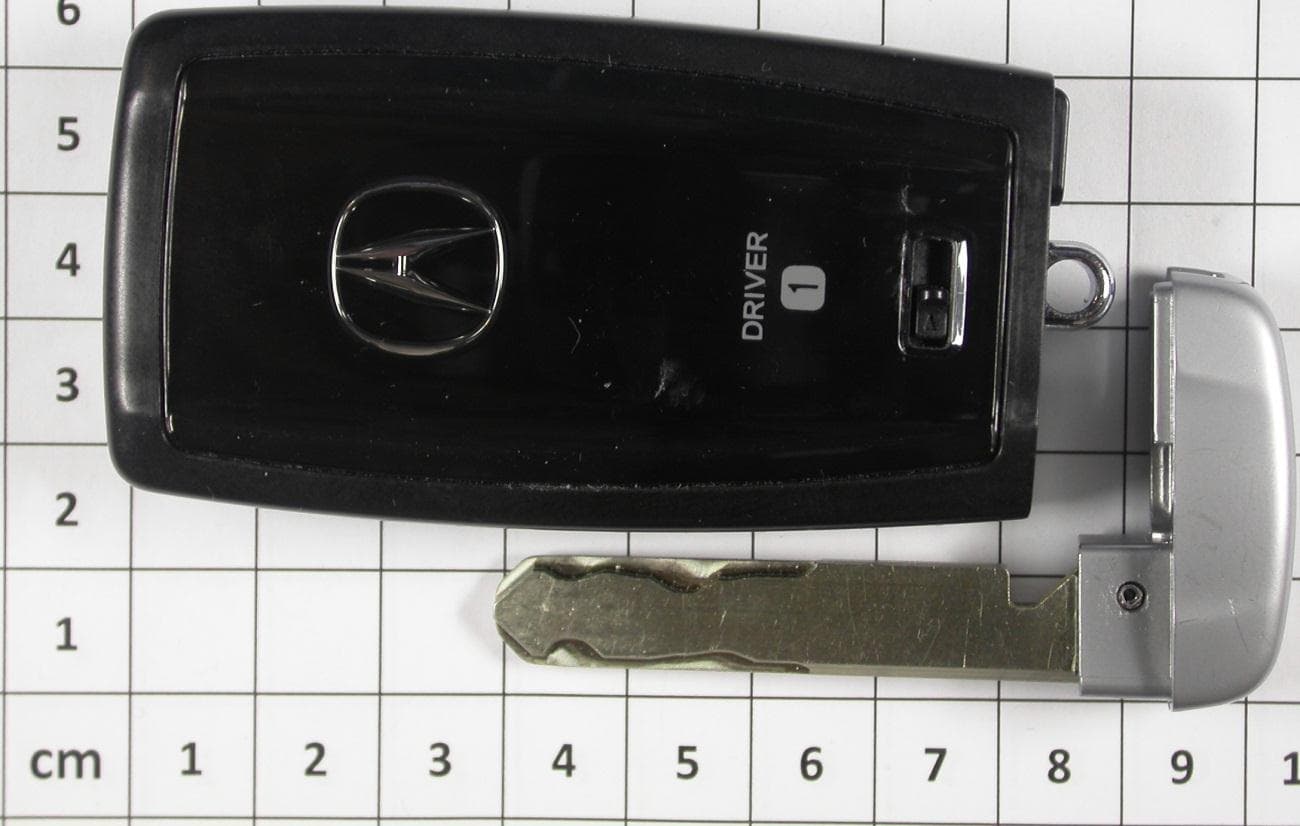
Click to zoom
Application Details
- Equipment Class
- DXT - Part 15 Low Power Transceiver, Rx Verified
- Date of Grant
- Feb 07, 2013
- Application Purpose
- Original Equipment
- Date of Application
- Feb 07, 2013
- Equipment Note
- Remote Transceiver for Car Access
- Frequency Range
- 923.45650000 - 924.09350000
- Country
- Germany
Documents & Files
Document Text
Text extracted from the exhibit documents filed with the FCC. Open a document above to read the original.
Users Manual
Continental AG I BS PG3 CFRF WM User Manual of the Continental Radio Frequency Bidirectional Key Fob Type Acura Bidir Fob MY13.5 A2C37924100 Continental AG I BS PG3 CFRF WM GENERAL DESCRIPTION OF THE RF TRANSMITTER The Acura Bidir Fob is a bidirectional RF key designed to provide remote engine start with feedback, remote keyless entry, passive entry, passive engine start, and immobilization functionality. The Acura Bidir Fob has a housing, which may have variants in the pictogram “Trunk”, alternatively “Power-Tail-Gate”(PTG): Continental AG I BS PG3 CFRF WM Feedback on Bidir Fob There exist 3 LEDs for all feedback, at the top of the fob, out of the way of the hand that is holding it. LEFT LED Color : AMBER Function: To show RF communication, or that 2-way communication is taking place. Example: LEFT/AMBER LED flashes 1x in response to a button being pressed when the RF command is sent, and/or it can flash while communicating with the vehicle, or waiting for response (example: while engine is cranking) . Also this LED will blink in response to SMART entry authentication. For other cases, generally the Amber LED should operate in a manner that is respective of the "Base SMART key". CENTER LED Color: GREEN. Function: Used to show positive feedback for a given command. Example: CENTER/GREEN LED is on for 1 second, to provide status feedback for a given operation. It means: Doors were locked, or engine was started, or engine is ON. RIGHT LED Color: RED. Function: Used to show negative feedback for a given command. There are 2 modes. 1. Out of range. In this case the red LED blinks distinctly 3 times, Example: 3 times in 1 second. It means the fob could not get acknowledgement from the car for 2-way communication, or the vehicle battery is dead and cannot respond. 2. Cannot Lock or Engine not running. In this case the red LED is on for 1 second. Continental AG I BS PG3 CFRF WM POWER MANAGEMENT The Power Supply comprises a coin cell battery CR2032, filter capacitors, diodes, and FETs, that provides power to the microcontroller, the power- management with charger and the RF circuit. A rechargeable battery (accu) of the type LiFePO4 is included to supply higher currents in case of long range transmission. The accu type LiFePO4 is of the class Li-Ion cell, but with a safe chemistry. There exists a certificate, that it is not dangerous / harmfull in the sense of UN3480 and "Transportation without Class 9 is allowed". Continental AG I BS PG3 CFRF WM 6. TESTMODE FUNCTION The testmode function is only available by EEPROM settings, which could provided only in specially programmed samples for measuring purpose. Button functions Button description red LED green LED amber LED ENG.START no function LOCK TX CW Modes X X UNLOCK TX Modulated Modes X X TRUNK RX Modes X X X PANIC another inner function X X X By pressing the specified button, the previously defined channels are revolving. The Lock button revolves the 8 Channels CW-mode till TX-off 3x red LED flash 1 , TX OFF all LEDs OFF switch to bat-supply, TX ON, TX-SR-CH1, CW-f_low TX-SR-CH1, CW-f_high TX-SR-CH2, CW-f_low TX-SR-CH2, CW-f_high switch to accu-supply, TX-LR-CH1, CW-f_low 2 TX-LR-CH1, CW-f_high 2 TX-LR-CH2, CW-f_low 2 TX-LR-CH2, CW-f_high 2 Notes: 1 : 3x red flash: 200ms on, 200ms off, 200ms on, 200ms off, 200ms on, off 2 : ATIC134 Lite option only Continental AG I BS PG3 CFRF WM The Unock button revolves the 4 modulated channels till TX-off The Trunk button revolves the 2 Receive-Channels till RX-off 3x red LED flash 1 , RX OFF all LEDs OFF switch to bat-supply, RX ON, 1x green&red LED flash, RX-SR-CH1 2x green&red LED flash, RX-SR-CH2 3x green&red LED flash, RX-LR-CH1 4x green&red LED flash RX-LR-CH2 Notes: 1 : 3x red flash: 200ms on, 200ms off, 200ms on, 200ms off, 200ms on, off 1x amber LED flash 1x amber LED flash 1x amber LED flash 1x amber LED flash 3x red LED flash 1 , TX OFF all LEDs OFF switch to bat- supply, TX ON, TX-SR- CH1, mod. TX-SR-CH2, mod. switch to accu- supply, TX- LR-CH1, mod. 2 TX-LR-CH2, mod. 2 Notes: 1 : 3x red flash: 200ms on, 200ms off, 200ms on, 200ms off, 200ms on, off 2 : ATIC134 Lite, test signal data content: zeros Continental AG I BS PG3 CFRF WM 7. LABEL DESIGN CANADA IC:7812D-37924100 USA FCC ID:KR537924100 The print is visible after opening the Fob like for battery change. How to open the Bidir Fob for Battery Change Take a coin (best fit: 2€, or a Quarter Dollar), press it into the groove and turn it against the metallic eyelet counterclockwise. For closing follow the instruction:
Users Manual
The device under test is manufactured by the grantee (Continental Automotive GmbH) and sold as an OEM product. Per 47 CFR 2.909, 2.927, 2.931, 2.1033, 15.15(b) etc..., the grantee must ensure the end-user has all applicable / appropriate operating instructions. When end-user instructions are required, as in the case of this product, the grantee must notify the OEM to notify the enduser. Continental Automotive GmbH will supply this document to the reseller/distributor dictating what must be included in the end user’s manual for the commercial product. INFORMATION TO BE INCLUDED IN THE END USER'S MANUAL The following information (in blue) must be included in the end product user’s manual to ensure continued FCC and Industry Canada regulatory compliance. The ID numbers must be included in the manual if the device label is not readily accessible to the end user. The compliance paragraphs below must be included in the user's manual. ****************************************************************************** FCC ID:KR537924100, IC:7812D-37924100 This device complies with Part 15 of the FCC Rules and with Industry Canada license-exempt RSS standard(s) . Operation is subject to the following two conditions: (1) This device may not caus e harmful interference, and (2) This device must accept any interference received, including interference that may cause undesired operation. Le présent appareil est conforme aux C NR d'Industrie Canada applicables aux appareils radio exempts de licence. L'expl oitation est autorisée aux deux c onditions suivantes: (1) l'appareil ne doit pas produire de brouillage, et (2) l'utilis ateur de l'appareil doit accepter tout brouillage radioélectrique subi, même si le brouillage est susceptible d'en compromettre le fonctionnement. Note: Changes or modifications not expressively approved by the party responsible for compliance could void the us er's authority to operate the equipment. The term “IC:” before the radio cert ification number only signifies that Industry Canada technical specifications were met. ******************************************************************************
Cover Letter(s)
Continental Automotive GmbH Siemensstr. 12 93055 Regensburg Postfach 100 953 93009 Regensburg Phone +49 941 790-0 Fax +49 941 790-4999 www.continental-corporation.com Registered Office: Hanover Registered Court: Amtsgericht Hanover HRB 59424 General Managers: Gerard Cordonnier, Helmut Matschi, Harald Stuhlmann November 28,2012 Your message dated Our Reference Your reference Subject: Confidentiality Request for FCC ID: KR537924100 IC: 7812D-37924100 Pursuant to FCC 47 CRF 0.457(d) and 0.459 and IC RSP-100, Section 10, the applicant requests that a part of the subject FCC application be held confidential. Type of Confidentiality Requested Exhibit Short Term Permanent Block Diagrams Short Term External Photos Short Term Permanent* 1 Internal Photos Short Term Permanent Operation Description/Theory of Operation Short Term Permanent Parts List & Placement/BOM Short Term Permanent Tune-Up Procedure Short Term Permanent Schematics Short Term Test Setup Photos Short Term Permanent* User’s Manual *Note: ______(Insert Explanation as Necessary)______ Continental Automotive GmbH has spent substantial effort in developing this product and it is one of the first of its kind in industry. Having the subject information easily available to "competition" would negate the advantage they have achieved by developing this product. Not protecting the details of the design will result in financial hardship. 1 - The asterisked items (*) require further justification before permanent confidentiality will be allowed. These also currently require review by the FCC under their Permit-But-Ask policy before the grant is issued and can delay completion of an application. Further justification should be added to the note above. One such example for a potted device would be: “The EUT is FULLY potted using a non-removable epoxy based material. Removal of potting material causes irreparable damage to internal circuitry. See photographs exhibits that outline the device before and after potting.” Dagmar Kolar QL RBG 43 Tel. +49 941 790-6699 Fax +49 941 790-996699 dagmar.kolar@continental- corporation.com Continental Automotive GbmH – Postfach 10 09 43 – 93009 Regensburg - 2 - Permanent Confidentiality: The applicant requests the exhibits listed above as permanently confidential be permanently withheld from public review due to materials that contain trade secrets and proprietary information not customarily released to the public. Short-Term Confidentiality: The applicant requests the exhibits selected above as short term confidential be withheld from public view for a period of ___(specify number of days not to exceed 180 ) 2 ___ days from the date of the Grant of Equipment Authorization and prior to marketing. This is to avoid premature release of sensitive information prior to marketing or release of the product to the public. Applicant is also aware that they are responsible to notify ACB in the event information regarding the product or the product is made available to the public. ACB will then release the documents listed above for public disclosure pursuant to FCC Public Notice DA 04-1705. NOTE for Industry Canada Applications: The applicant understands that until such time that IC distinguishes between Short Term and Permanent Confidentiality, either type of marked exhibit above will simply be marked Confidential when submitted to IC. Sincerely, By: ______________________________ Dagmar Kolar / Manager RF Homologation 2 - Please refer to http://acbcert.com/documents/misc-docs/Memo-Short-Term-Vs-Standard-Confidentiality.pdf for complete details.
External Photos
Attachment A to File No.: T36340-01 1 P h o t o d o c u m e n t a t i o n o f t h e E U T 1.1 External views:
ID Label/Location Info
FCC ID:KR537924100 IC:7812D-37924100 I:\POSTZULA\z1_Projekte\A_Aktuell\Honda\MY14\MY14 - BIDIR KEY\Technische_Doku_doc\Label_Owner-Manual.doc Page 1 of 2 Continental Radio Transmitter A2C37924100 Label Information: Continental A2C37924100 FCC ID:KR537924100 IC:7812D-37924100 FCC ID:KR537924100 IC:7812D-37924100 I:\POSTZULA\z1_Projekte\A_Aktuell\Honda\MY14\MY14 - BIDIR KEY\Technische_Doku_doc\Label_Owner-Manual.doc Page 2 of 2 Owner Manual USA FCC ID:KR537924100 This device complies with Part 15 of the FCC Rules. Operation is subject to the following two conditions: (1) this device may not cause harmful interference, and (2) this device must accept any interference received, including interference that may cause undesired operation. Changes or modifications not expressly approved by the party responsible for compliance could void the user's authority to operate the equipment.
ID Label/Location Info
American Certification Body, Inc. 6731 Whittier Ave. Suite C110 McLean, VA 22101 We confirm that we already informed our client about the labeling rules of the FCC KDB 784748 and about the fact that the device must arrive ‘open’ to the user, so that the regulatory markings are visible during shipment and upon arrival. 25.01.2013 __________________________ (Signature) Thomas Ring Manager Certification mikes-testingpartners gmbh (Company Name) email: [email protected] Telephone:+49 9424 9481-214
Internal Photos
1.2 Internal views:
Test Report
FCC ID: KR537924100 IC ID: 7812D-37924100 mikes-testingpartners gmbh File No. T36340-01-00HU, page 1 of 33 Ohmstrasse 2-4 94342 STRASSKIRCHEN GERMANY Tel.:+49(0)9424-94810 Fax:+49(0)9424-9481240 Rev. No. 1.2, 2010-09-09 EMI − T E S T R E P O R T - FCC Part 15.249, RSS210 - Test Report No. : T36340-01-00HU 21. December 2012 ______________________________________________________________________________________________ Date of issue Type / Model Name : Honda Acura BiDir Smart KeyFob My13.5/MY14 Product Description : Remote Transceiver for Car access Applicant : Continental Automotive GmbH Address : Siemensstr. 12 93055 Regensburg Manufacturer : Continental Guadalajara Tijera Address : Camino a la Tijera No.3 45640 Tlajomulco de Zuῇiga, Jalisco, Mexico Licence holder : Continental Automotive GmbH Address : Siemensstr. 12 93055 Regensburg Test Result according to the standards listed in clause 1 test standards: POSITIVE The test report merely corresponds to the test sample. It is not permitted to copy extracts of these test results without the written permission of the test laboratory. FCC ID: KR537924100 IC ID: 7812D-37924100 mikes-testingpartners gmbh File No. T36340-01-00HU, page 2 of 33 Ohmstrasse 2-4 94342 STRASSKIRCHEN GERMANY Tel.:+49(0)9424-94810 Fax:+49(0)9424-9481240 Rev. No. 1.2, 2010-09-09 Contents 1 T E S T S T A N D A R D S 3 2 S U M M A R Y 4 2.1 Test result summery 4 2.2 GENERAL REMARKS: 5 2.3 FINAL ASSESSMENT: 5 3 E Q U I P M E N T U N D E R T E S T 6 3.1 Photo documentation of the EUT – Please see attachment A 6 3.2 Power supply system utilised 6 3.3 Short description of the equipment under test (EUT) 6 4 T E S T E N V I R O N M E N T 7 4.1 Address of the test laboratory 7 4.2 Environmental conditions 7 4.3 Statement of the measurement uncertainty 7 4.4 Measurement protocol for FCC and IC 8 5 T E S T C O N D I T I O N S A N D R E S U L T S 10 5.1 Conducted emissions 10 5.2 Radiated emission of the fundamental wave 11 5.3 Spurious emissions radiated 13 5.4 20 dB bandwidth 18 5.5 Bandwidth of momentary signals 24 5.6 Antenna application 29 5.7 Receiver radiated emissions 30 6 U S E D T E S T E Q U I P M E N T A N D A C C E S S O R I E S 33 FCC ID: KR537924100 IC ID: 7812D-37924100 mikes-testingpartners gmbh File No. T36340-01-00HU, page 3 of 33 Ohmstrasse 2-4 94342 STRASSKIRCHEN GERMANY Tel.:+49(0)9424-94810 Fax:+49(0)9424-9481240 Rev. No. 1.2, 2010-09-09 1 T E S T S T A N D A R D S The tests were performed according to following standards: FCC Rules and Regulations Part 15, Subpart A - General (October, 2012) Part 15, Subpart A, Section 15.31 Measurement standards Part 15, Subpart A, Section 15.33 Frequency range of radiated measurements Part 15, Subpart A, Section 15.35 Measurement detector functions and bandwidths FCC Rules and Regulations Part 15, Subpart C - Intentional Radiators (October, 2012) Part 15, Subpart C, Section 15.203 Antenna requirement Part 15, Subpart C, Section 15.204 External radio frequency power amplifiers and antenna modifications Part 15, Subpart C, Section 15.205 Restricted bands of operation Part 15, Subpart C, Section 15.207 Conducted limits Part 15, Subpart C, Section 15.209 Radiated emission limits, general requirements Part 15, Subpart C, Section 15.249 Operation within the bands 902 - 928 MHz, 2400 - 2483.5 MHz, 5725 - 5875 MHz, and 24.0 - 24.25 GHz ANSI C63.4: 2009 Methods of Measurement of Radio-Noise Emissions from Low- Voltage Electrical and Electronic Equipment in the Range of 9 kHz to 40 GHz. CISPR 16-4-2: 2003 Uncertainty in EMC measurement CISPR 22: 2005 Information technology equipment EN 55022: 2006 FCC ID: KR537924100 IC ID: 7812D-37924100 mikes-testingpartners gmbh File No. T36340-01-00HU, page 4 of 33 Ohmstrasse 2-4 94342 STRASSKIRCHEN GERMANY Tel.:+49(0)9424-94810 Fax:+49(0)9424-9481240 Rev. No. 1.2, 2010-09-09 2 S U M M A R Y 2.1 Test result summery The Acura Bidir Fob is a bidirectional RF key for vehicular use: Operating in the 902 MHz – 928 MHz band: FCC Rule Part RSS Rule Part Description Result 15.207(a) RSS Gen, 7.2.4 AC power line conducted emissions not applicable 15.215(c) RSS Gen, 4.6.3 -20 dBc EBW not applicable 15.249(a) RSS-210, A8.4(4) Field strength of fundamental passed 15.249(d) RSS-210, A8.5 Out-of-band emission, radiated passed 15.205(a) RSS-Gen, 7.2.2 Emissions in restricted bands passed 15.35(c) RSS-Gen, 4.5 Pulsed operation not applicable 15.107 RSS Gen, 7.2.4. AC power line conducted emissions not applicable RSS-Gen, 7.2.6 Transmitter frequency stability not applicable RSS-Gen, 4.6.1 99 % Bandwidth passed OET Bulletin 65 RSS102, 3.2 Co-location, Co-transmission not applicable The mentioned RSS Rule Parts in the above table are related to: RSS Gen, Issue 3, December 2010 RSS 210, Issue 8, December 2010 RSS 102, Issue 4, March 2010 FCC ID: KR537924100 IC ID: 7812D-37924100 mikes-testingpartners gmbh File No. T36340-01-00HU, page 5 of 33 Ohmstrasse 2-4 94342 STRASSKIRCHEN GERMANY Tel.:+49(0)9424-94810 Fax:+49(0)9424-9481240 Rev. No. 1.2, 2010-09-09 2.2 GENERAL REMARKS: All radiated tests have been performed on samples which are in original state in a test mode function. The testmode function is only available by EEPROM settings, which could provided only in specially programmed samples for measuring purpose. Button functions Button description red LED green LED amber LED ENG.START no function LOCK TX CW Modes X X UNLOCK TX Modulated Modes X X TRUNK RX Modes X X X PANIC another inner function X X X By pressing the specified button, the previously defined channels are revolving. The EuT has an incorporated antenna and is powered by a primary battery. 2.3 FINAL ASSESSMENT: The equipment under test fulfills the EMI requirements cited in clause 1 test standards. Date of receipt of test sample : acc. to storage records Testing commenced on : 03. December 2012 Testing concluded on : 18. December 2012 Checked by: Tested by: Klaus Gegenfurtner Dipl.-Ing.(FH) Manager Radio Group Markus Hube…
Text truncated - open the document above for the full version.
Test Setup Photos
FCC ID: KR537924100 IC ID: 7812D-37924100 mikes-testingpartners gmbh File No. T36340-01-00HU, page 11 of 33 Ohmstrasse 2-4 94342 STRASSKIRCHEN GERMANY Tel.:+49(0)9424-94810 Fax:+49(0)9424-9481240 Rev. No. 1.2, 2010-09-09 5.2 Radiated emission of the fundamental wave For test instruments and accessories used see section 6 Part CPR 2. 5.2.1 Description of the test location Test location: OATS 1 Test distance: 3 m 5.2.2 Photo documentation of the test set-up 5.2.1 Applicable standard According to FCC Part 15C, Section 15.249(a): The field strength of emissions from intentional radiators operated within these frequency bands shall comply with the effective limits. 5.2.2 Description of Measurement The radiated power of the fundamental wave from the EUT is measured in the frequency range of 30 to 1000 MHz using a tuned receiver and appropriate broadband linearly polarized antennas. Measurements between 30 MHz and 1000 MHz are made with 120 kHz/6 dB bandwidth and quasi-peak detection. Table top equipment is placed on a 1.0 X 1.5 meter non-conducting table 80 centimetres above the ground plane. Floor standing equipment is placed directly on the turntable/ground plane. The set up of the Equipment under test will be in accordance to ANSI C63.4- 2003. The Interface cables that are closer than 40 centimetres to the ground plane are bundled in the center in a serpentine fashion so they are at least 40 centimetres from the ground plane. Cables to simulators/testers (if used in this test) are routed through the center of the table and to a screen room located outside the test area. The antenna was positioned 3, 10 or 30 meters horizontally from the EuT. To locate maximum emissions from the test sample the antenna is varied in height from 1 to 4 meters, measurement scans are made with both horizontal and vertical antenna polarization`s and the EuT are rotated 360 degrees. FCC ID: KR537924100 IC ID: 7812D-37924100 mikes-testingpartners gmbh File No. T36340-01-00HU, page 13 of 33 Ohmstrasse 2-4 94342 STRASSKIRCHEN GERMANY Tel.:+49(0)9424-94810 Fax:+49(0)9424-9481240 Rev. No. 1.2, 2010-09-09 5.3 Spurious emissions radiated For test instruments and accessories used see section 6 Part SER1, SER 2, SER 3. 5.3.1 Description of the test location Test location: OATS 1 Test location: Anechoic chamber 2 Test distance: 3 m 5.3.2 Photo documentation of the test set-up FCC ID: KR537924100 IC ID: 7812D-37924100 mikes-testingpartners gmbh File No. T36340-01-00HU, page 14 of 33 Ohmstrasse 2-4 94342 STRASSKIRCHEN GERMANY Tel.:+49(0)9424-94810 Fax:+49(0)9424-9481240 Rev. No. 1.2, 2010-09-09 5.3.3 Applicable standard According to FCC Part 15C, Section 15.249 (d): Emission radiated outside of the specified frequency bands, except harmonics, shall be attenuated by at least 50 dB below the level of the fundamental or to the general radiated limit in FCC Part 15C, Section 15.209, whichever is the lesser attenuation. 5.3.4 Description of Measurement The radiated emissions from the EUT are measured in the frequency range of 9 kHz to 1000 MHz using a tuned receiver and appropriate broadband linearly polarized antennas. The set up of the EUT will be in accordance to ANSI C63.4. In the frequency range above 1 GHz a spectrum analyser is used with appropriate linear polarized antennas. If the emission level in peak mode complies with the average limit then testing will be stopped and peak values of the EUT will be reported, otherwise, the emission will be measured in average mode again and reported. During the test, the EUT was set into continuous transmitting mode modulated. Instrument settings: 9 kHz – 150 kHz RBW: 200 Hz 150 kHz - 30 MHz RBW: 9 kHz 30 MHz – 1000 MHz: RBW: 120 kHz 1000 MHz – 40 GHz RBW: 1 MHz FCC ID: KR537924100 IC ID: 7812D-37924100 mikes-testingpartners gmbh File No. T36340-01-00HU, page 18 of 33 Ohmstrasse 2-4 94342 STRASSKIRCHEN GERMANY Tel.:+49(0)9424-94810 Fax:+49(0)9424-9481240 Rev. No. 1.2, 2010-09-09 5.4 20 dB bandwidth For test instruments and accessories used see section 6 Part MB. 5.4.1 Description of the test location Test location: Shielded Room S5 5.4.2 Photo documentation of the test set-up 5.4.3 Applicable standard According to FCC Part 15, Section 15.215(c): Intentional radiators operating under the alternative provisions to the general emission limits, as contained in Section 15.217 through Section 15.257, must be designed to ensure that the 20 dB bandwidth of the emission is contained within the frequency band designated in the rule section under which the equipment is operated. 5.4.4 Description of Measurement The bandwidth is measured at an amplitude level reduced from the reference level by a specified ratio of -20 dB. The reference level is the level of the highest signal amplitude observed from the transmitter at the fundamental frequency. Alternative is the x-dB-down function of the analyser used. The EBW is than directly shown in the marker display. The measurement is performed with normal modulation and a transfer rate means the worst case. FCC ID: KR537924100 IC ID: 7812D-37924100 mikes-testingpartners gmbh File No. T36340-01-00HU, page 24 of 33 Ohmstrasse 2-4 94342 STRASSKIRCHEN GERMANY Tel.:+49(0)9424-94810 Fax:+49(0)9424-9481240 Rev. No. 1.2, 2010-09-09 5.5 Bandwidth of momentary signals For test instruments and accessories used see section 6 Part MB. 5.5.1 Description of the test location Test location: Shielded Room S5 5.5.2 Photo documentation of the test set-up 5.5.3 Test result Fundamental frequency (MHz) 99% bandwidth f1 (MHz) 99% bandwidth f2 (MHz) Measured bandwidth (MHz) Limit (MHz) 923.9065 923.876 923.948 0.072 4.62 923.6065 923.576 923.648 0.072 4.62 923.4565 923.448 923.477 0.029 4.62 924.0565 924.048 924.077 0.029 4.62 Limit according to RSS 210, Annex 1, section A1.1.3: The 99% bandwidth shall be no wider than 0.50% of the center frequency for devices operating above 900 MHz. The requirements are FULFILLED. Remarks: For detailed results, p…
Text truncated - open the document above for the full version.
Contact Information
Applicant
Thomas Heselberger
Technical Contact
Test Firm
CSA Group Bayern GmbHThomas Weise
Technical Specifications
| # | Rule Parts | Frequency Range | Power Output |
|---|---|---|---|
| 1 | 15C | 923.4565 MHz - 924.0935 MHz | - |
Other Applications from Continental Automotive Technologies GmbH
KR5FERKEY25
Jul 06, 2026Romete Car Key
Equipment Class
DSC - Part 15 Security/Remote Control TransmitterKR5KAM01
May 12, 2026KAM (Key Authentication Module)
Equipment Class
DCD - Part 15 Low Power Transmitter Below 1705 kHzKR5HFM501
Apr 29, 2026Hand Free Module
Equipment Class
DCD - Part 15 Low Power Transmitter Below 1705 kHzKR5TXPZ6
Mar 05, 2026Radio Frequency Transmitter
Equipment Class
DSC - Part 15 Security/Remote Control TransmitterKR5TXPZ5
Mar 05, 2026TXPZ5
Equipment Class
DSC - Part 15 Security/Remote Control Transmitter