KR55WK45032RF Transmitter 5wk4 5032 315MHz
Continental Automotive Technologies GmbH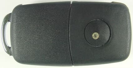
Click to zoom
Application Details
- Equipment Class
- DSC - Part 15 Security/Remote Control Transmitter
- Date of Grant
- Feb 06, 2001
- Application Purpose
- Original Equipment
- Date of Application
- Feb 06, 2001
- Equipment Note
- RF Transmitter 5wk4 5032 315MHz
- Frequency Range
- 314.92500000 - 315.07500000
- Country
- Germany
Documents & Files
Document Text
Text extracted from the exhibit documents filed with the FCC. Open a document above to read the original.
Users Manual
FCC ID: KR55WK45032 File: s:\postzula\vw\kessy\func_5wk45032_epage 1 of 4 User Manual / Functional Description of the Siemens RF Transmitter 5WK4 5032315 MHz Language: English FCC ID: KR55WK45032 File: s:\postzula\vw\kessy\func_5wk45032_epage 2 of 4 General description of the RF transmitter The 315 MHz RF remote control system consisting of a RF transmitter and a RF receiver mounted within the control unit. The RF transmitter is mechanically integrated in the head of the key. This transmitter is used to transmit an information for locking or unlocking the vehicle by an unidirectional RF transmission line for normal remote operation by pressing a button. For passive access functionality the transmitter is able to reply to an inductive command with sending a remote telegramme. In general the following functions are provided by pressing the buttons: - Lock the car - Unlock the car - Unlock trunc Additional the following functions are provided (Keyless Entry/Go Functions): - Lock/Unlock the car - Start/Stop the engine Power supply The transmitter is provided with 1 Lithium battery (CR2032) that gives a tension of feeding of +3V. The battery inversion is protected mechanically. Buttons There are three buttons which enable to lock, unlock the doors and unlock the trunk. During activation, the button is forced to the ground via a “pull-up” within the microcontroller. LED The LED is turned on between transmission blocks. FCC ID: KR55WK45032 File: s:\postzula\vw\kessy\func_5wk45032_epage 3 of 4 Oscillator The oscillator is of PLL type. The operating frequency is about 315 MHz ± 75 kHz. Mechanical design The mechanical of the transmitter is composed of four parts: the superior shell the inferior shell metal insert battery support (mechanical protection to afford battery inversion ) The battery placement is integrated in the inferior shell. Technical data Carrier frequency315 MHz ± 75 kHz Output Power< -18 dBm (carrier frequency) Type of modulationASK Method of frequency generationCrystal Number of channels1 Baudrate2 k Baud Power supply3 Volt Type of batteryLithium Transmission rangetypical 10 meters FCC ID: KR55WK45032 File: s:\postzula\vw\kessy\func_5wk45032_epage 4 of 4 Typical usage pattern 27 lock / unlock operations in 24 hours with a typical transmission duration of 500 milliseconds Transmitter ON13,5seconds / 24 hours Transmitter OFF86.386,5seconds / 24 hours Duty Cycle: T ON / T (ON+OFF) x 100% = 13,5 / 86.400 x 100 % = 0,015 % Block diagram of the transmitter Label design Setup of homologation testing samples For homologation testing the testing samples are equipped with continuous transmission mode. After inserting the battery the transmitter starts continous transmission until the battery is removed. These special function have only been implemented for the testing related to radio homologation. This procedure does not correspond to the standard mode of operation!!! LED Antenna RF stage μC Transponder / inductive receiver Power Buttons Siemens 315 MHz, 5WK4 5032 3D0 959 753 KWJJ FCC ID: KR55WK45032 CAN: xxx xxx xxxx
Attestation Statements
ATTESTATION STATEMENT FCC ID: KR55WK45032 RF Transmitter 5WK4 5032 SUMMARY: All tests according to FCC Part Subpart C Paragraph 15.231 ! - Performed The equipment under test ! - Fulfills the general approval requirements of FCC Part Subpart C Paragraph 15.231 - MIKES BABT PRODUCT SERVICE GmbH - Responsible Engineer _____________________________ Josef Knab
Block Diagram
FCC ID: KR55WK45032 Block diagram of the transmitter LED Antenna RF stage μC Transponder / inductive receiver Power Buttons
External Photos
FCC ID: KR55WK45032 Attachment E 1 5WK4 5022 File-No. T 19905-01 KJ MIKES BABT Product Service GmbH ! Ohmstrasse 2-4 ! 94342 Strasskirchen ! Tel.: +49 9424-94070 ! Fax: +49 9424-940760
ID Label/Location Info
FCC ID: KR55WK45032 Label design Siemens 315 MHz, 5WK4 5032 3D0 959 753 KWJJ FCC ID: KR55WK45032 CAN: xxx xxx xxxx
Internal Photos
FCC ID: KR55WK45032 Attachment E 2 5WK4 5022 File-No. T 19905-01 KJ MIKES BABT Product Service GmbH ! Ohmstrasse 2-4 ! 94342 Strasskirchen ! Tel.: +49 9424-94070 ! Fax: +49 9424-940760
Operational Description
FCC ID: KR55WK45032 Duty Cycle Typical usage pattern 27 lock / unlock operations in 24 hours with a typical transmission duration of 500 milliseconds Transmitter ON13,5seconds / 24 hours Transmitter OFF86.386,5seconds / 24 hours Duty Cycle: T ON / T (ON+OFF) x 100% = 13,5 / 86.400 x 100 % = 0,015 %
Operational Description
FCC ID: KR55WK45032 General description of the RF transmitter The 315 MHz RF remote control system consisting of a RF transmitter and a RF receiver mounted within the control unit. The RF transmitter is mechanically integrated in the head of the key. This transmitter is used to transmit an information for locking or unlocking the vehicle by an unidirectional RF transmission line for normal remote operation by pressing a button. For passive access functionality the transmitter is able to reply to an inductive command with sending a remote telegramme. In general the following functions are provided by pressing the buttons: - Lock the car - Unlock the car - Unlock trunc Additional the following functions are provided (Keyless Entry/Go Functions): - Lock/Unlock the car - Start/Stop the engine Power supply The transmitter is provided with 1 Lithium battery (CR2032) that gives a tension of feeding of +3V. The battery inversion is protected mechanically. Buttons There are three buttons which enable to lock, unlock the doors and unlock the trunk. During activation, the button is forced to the ground via a “pull-up” within the microcontroller. LED The LED is turned on between transmission blocks. FCC ID: KR55WK45032 Oscillator The oscillator is of PLL type. The operating frequency is about 315 MHz ± 75 kHz. Mechanical design The mechanical of the transmitter is composed of four parts: the superior shell the inferior shell metal insert battery support (mechanical protection to afford battery inversion ) The battery placement is integrated in the inferior shell. Technical data Carrier frequency315 MHz ± 75 kHz Output Power< -18 dBm (carrier frequency) Type of modulationASK Method of frequency generationCrystal Number of channels1 Baudrate2 k Baud Power supply3 Volt Type of batteryLithium Transmission rangetypical 10 meters
Test Report
FCC ID: KR55WK45032 TTI - P-G 009 / 98-00 TTI - P-G 089 / 94-50 File No. T 19905-1-01 KJ , Page 1 of 17 MIKES BABT PRODUCT SERVICE GmbH Ohmstrasse 2-4 94342 Strasskirchen Tel:+9424-9407-0 Fax:+9424-9407-60 Rev.No. 8.6 E M I S S I O N -- T E S T R E P O R T Testreport file no. : T 19905-1-01 KJ ______________ Date : December 13, 2000 of issue __________________ Model / Type No. : 5WK4 5032 ______________________________________________ Type : RF Transmitter ______________________________________________ Applicant : SIEMENS Automotive AG ______________________________________________ Manufacturer : SIEMENS Automotive AG ______________________________________________ Licence holder : SIEMENS Automotive AG ______________________________________________ Address : Wernerwerkstrasse 2 ______________________________________________ D-93049 Regensburg ______________________________________________ Test result accrdg. to the regulation(s) at page 3 : POSITIVE This testreport with appendix consists of 27 pages. The testresult only responds to the tested sample. It is not allowed to copy this report even partly without the allowance of the testlaboratory. FCC ID: KR55WK45032 File No. T 19905-1-01 KJ , Page 2 of 17 MIKES BABT PRODUCT SERVICE GmbH Ohmstrasse 2-4 94342 Strasskirchen Tel:+9424-9407-0 Fax:+9424-9407-60 Rev.No. 8.6 D I R E C T O R Y Page A) Documentation Directory2 ________ Testregulations3 ________ General information4-5 ________ Discovery of worst case condition 6 ________ Equipment under Test16 ________ Summary17 ________ B) Testdata Conducted emissions 10/150 kHz - 30 MHz 7 ________ Spurious emissions (magnetic field) 10 kHz - 30 MHz 8-9 ________ Spurious emissions (electric field) 30 MHz - 1000 MHz 10-11 ________ Spurious emissions (electric field) 1 GHz - 18 GHz 12-13 ________ Raiated power of the fundamental wave 14 ________ Conducted power of the fundamental wave measured on 15 the antenna terminals ________ Attachment A) Testdata / Bandwith plots A1-A2 ________ B) List of Test Equipment B1 ________ C) Photos of the test setup C1-C2 ________ D) Technical description of the test sample D1-D3 (e.g.CDF, Declaration) ________ E) Photos of the EuTE1-E2 ________ F) Measurement Protocol for FCC, VCCI and AUSTEL -- ________ FCC ID: KR55WK45032 File No. T 19905-1-01 KJ , Page 3 of 17 MIKES BABT PRODUCT SERVICE GmbH Ohmstrasse 2-4 94342 Strasskirchen Tel:+9424-9407-0 Fax:+9424-9407-60 Rev.No. 8.6 T E S T R E G U L A T I O N S The tests were performed according to following regulations : o - EN 50081-1 / 2.1991 o - EN 50081-2 / 7.1993 -------------------------------------------------------------------------------- o - EN 55011 / 3.1991 o - Group 1 o - Group 2 o - class A o - class B o - EN 55014 / 4.1993 o - Household appliances and similar o - tools o - Semiconductor devices o - EN 55014 / A2:1990 o - EN 55104 / 5.1995 Category: o - EN 55015 / A1:1990 o - EN 55015 / 12.1993 o - EN 55022 / 5.1995 o - class A o - class B o - prEN 55103-1/ 3.1995 o - prEN 50121-3-2 / 3.1995 o - EN 60601-1-2 / 4.1994 o - VCCI o - class 1 o - class 2 o - Part 15 Subpart C (15.209) ! - Part 15 Subpart C (15.231) FCC ID: KR55WK45032 File No. T 19905-1-01 KJ , Page 4 of 17 MIKES BABT PRODUCT SERVICE GmbH Ohmstrasse 2-4 94342 Strasskirchen Tel:+9424-9407-0 Fax:+9424-9407-60 Rev.No. 8.6 A D D R E S S O F T H E T E S T L A B O R A T O R Y ! - MIKES BABT PRODUCT SERVICE GmbH Ohmstrasse 2-4 D - 94342 Strasskirchen o - ______________________________________ ______________________________________ ______________________________________ E N V I R O N M E N T A L C O N D I T I O N S Temperature: 15-35 ° C ______ Humidity 45-60 % ______ Atmospheric pressure 860-1060 mbar _________ POWER SUPPLY SYSTEM UTILIZED Power supply system : Battery Unom = 3 V DC STATEMENT OF MEASUREMENT UNCERTAINTY The data and results referenced in this document are true and accurate. The reader is cautioned that there may be errors within the calibration limits of the equipment and facilities that can account for a nominal measurement error of ± 4dB. Furthermore, component and process variability of devices similar to that tested may result in additional deviation. The manufacturer has the sole responsibility of continued compliance of the device. SHORT DESCRIPTION OF THE EQUIPMENT UNDER TEST (EUT) The 315 MHz RF remote control system consists of a RF transmitter and a RF receiver mounted within the control unit. The RF transmitter is mechanically integrated in the head of the key. This transmitter is used to transmit an information for locking or unlocking the vehicle by an unidirectional RF transmission line for normal remote operation by pressing a button. For passive access functionality the transmitter is able to reply to an inductive command with sending a remote telegramme. Number of received/tested samples: 2 / 2 Serial Number: Prototype DEFINITIONS FOR SYMBOLS USED IN THIS TEST REPORT ! - Black box indicates that the listed condition, standard or equipment is applicable for this Report. o - Blank box indicates that the listed condition, standard or equipment was not applicable for this Report. FCC ID: KR55WK45032 File No. T 19905-1-01 KJ , Page 5 of 17 MIKES BABT PRODUCT SERVICE GmbH Ohmstrasse 2-4 94342 Strasskirchen Tel:+9424-9407-0 Fax:+9424-9407-60 Rev.No. 8.6 M E A S U R E M E N T P R O T O C O L F O R F C C , V C C I A N D A U S T E L Test Methodology Conducted and radiated emission testing is performed according to the procedures in International Special Committee on Radio Interference (CISPR) Publication 22 (1993), European Standard EN 55022 and Australian Standard AS 3548 (which are based on CISPR 22). The Japanese standard, "Voluntary Control Council for Interference (VCCI) by Data Processing Equipment and Electronic Office Machines, Technical Requirements" is technically equivalent to CISPR 22 (1993). For official compliance, a conformance report must be sent to and accepted by the VCCI. In compliance with FCC Docket 92-152, "Harm…
Text truncated - open the document above for the full version.
Test Setup Photos
FCC ID: KR55WK45032 File No. T 19905-1-01 KJ , Page C 1 of C 2 MIKES BABT PRODUCT SERVICE GmbH " Ohmstrasse 2-4 " D-94342 Strasskirchen " Tel.:+49 94 24 94 07-0 " Fax:+49 94 24 94 07-60 Rev.Nr. 8.6 Test-Setup: SPURIOUS EMISSIONS (electric field) 30 MHz - 1000 MHz FCC ID: KR55WK45032 File No. T 19905-1-01 KJ , Page C 2 of C 2 MIKES BABT PRODUCT SERVICE GmbH " Ohmstrasse 2-4 " D-94342 Strasskirchen " Tel.:+49 94 24 94 07-0 " Fax:+49 94 24 94 07-60 Rev.Nr. 8.6 Test-Setup: SPURIOUS EMISSIONS (electric field) 1 GHz - 18 GHz
Contact Information
Applicant
Thomas Heselberger
Test Firm
MIKES BABT Product Service GmbHHarald Buchwald
Technical Specifications
| # | Rule Parts | Frequency Range | Power Output | Emission | Tolerance |
|---|---|---|---|---|---|
| 1 | 15.231 | 314.925 MHz - 315.075 MHz | 1.00 mW | K1D | 75.0000000000 ppm |
Other Applications from Continental Automotive Technologies GmbH
KR5FERKEY25
Jul 06, 2026Romete Car Key
Equipment Class
DSC - Part 15 Security/Remote Control TransmitterKR5KAM01
May 12, 2026KAM (Key Authentication Module)
Equipment Class
DCD - Part 15 Low Power Transmitter Below 1705 kHzKR5HFM501
Apr 29, 2026Hand Free Module
Equipment Class
DCD - Part 15 Low Power Transmitter Below 1705 kHzKR5TXPZ6
Mar 05, 2026Radio Frequency Transmitter
Equipment Class
DSC - Part 15 Security/Remote Control TransmitterKR5TXPZ5
Mar 05, 2026TXPZ5
Equipment Class
DSC - Part 15 Security/Remote Control Transmitter