KR55WK48089Keyless Vehicle Module
Continental Automotive Technologies GmbH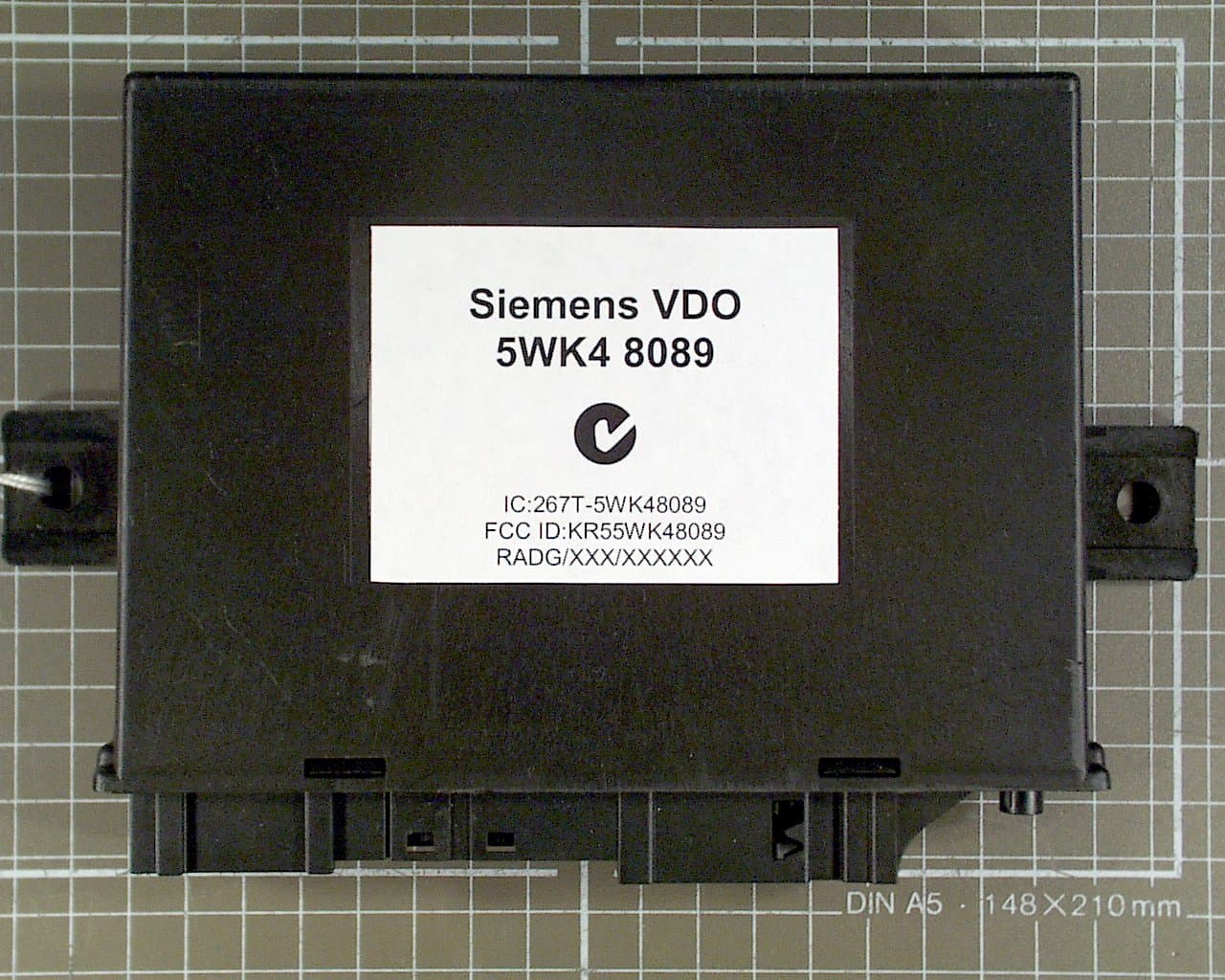
Click to zoom
Application Details
- Equipment Class
- DCD - Part 15 Low Power Transmitter Below 1705 kHz
- Date of Grant
- Jan 02, 2005
- Application Purpose
- Original Equipment
- Date of Application
- Jan 02, 2005
- Equipment Note
- Keyless Vehicle Module
- Frequency Range
- 0.12500000 - 0.12500000
- Country
- Germany
Documents & Files
Document Text
Text extracted from the exhibit documents filed with the FCC. Open a document above to read the original.
Users Manual
Annex No.5 Functional Description SIEMENS VDO Automotive AG SV C BC P2 RF TG FCC ID:KR55WK48089 IC:267T-5WK48089 File: D:\Postzula\Kunden\Mb\W221\FunctionalDiscription_W221.doc Page 1 of 1 Functional Description / User Manual of the Siemens VDO Keyless Vehicle Module type 5WK4 8079 5WK4 8089 SIEMENS VDO Automotive AG SV C BC P2 RF TG FCC ID:KR55WK48089 IC:267T-5WK48089 File: D:\Postzula\Kunden\Mb\W221\FunctionalDiscription_W221.doc Page 2 of 2 General functional description The immobilizer system is equipment which enables comfortable operation of the vehicle. To be able to operate the vehicle the driver only has to take the key with him. The vehicle communicates with the key inductively via ferrite- antennas which are located in the front doors, in the interior of the car and in the bumper. These ferrite antennas are driven by inductance with a frequency of 125 kHz. By damping the body sheet-metal of the car, the system's range is kept in defined limits. The range of the interior antennas of the vehicle is the interior of the car only. This enables the locating of the key. The door handles and the trunk lid have been equipped with contacts for the functions "locking" and "unlocking" the vehicle. Woken up by pulling a door handle the immobilizer sends a challenge 125 kHz via the corresponding inductive door antenna to the key. The data transmitted in the process activate the key. The key sends a code to the radio receiver on the control unit via radio frequency transmission. The control unit transmits the data to the vehicle's "electronic ignition starter switch (EZS)”. If this code is assessed as valid in the EZS, the vehicle will be unlocked. If a lock command is send to the control module while the vehicle is unlocked, the EZS and the key interchange a code via the control module and the antennas. If the key is in the exterior area and the code is valid, the vehicle will be locked. If it is intended to start the engine of a vehicle, this requires actuation of a start key. The interior inductive antennas are activated. This is to ensure that the key is inside the vehicle. If the valid code is emitted by the key, the engine will start. If the code is invalid, the engine will not start. SIEMENS VDO Automotive AG SV C BC P2 RF TG FCC ID:KR55WK48089 IC:267T-5WK48089 File: D:\Postzula\Kunden\Mb\W221\FunctionalDiscription_W221.doc Page 3 of 3 List of variants 5WK4 8079 Control unit W221for ECE use 5WK4 8089 Control unit W221 for USA use 5WK4 8193 Ferrite antenna Block diagram The immobilizer system consists of a control unit, the inductive antennas and the key. To activate the system, sensors or push-buttons are located in the doors, in the trunk lid and in the interior. Interaction with the vehicle is effected via the radio receiver in the control module, which receives the messages from the key and transmits them via the vehicle's CAN bus to the EZS. Immobilzer Control unit with radio receiver ID Key Antennas in the doors, in the trunk lid and in the bumper Electronic ignition starter switch EZS CAN bus Wiring harnes s 125 kHz SIEMENS VDO Automotive AG SV C BC P2 RF TG FCC ID:KR55WK48089 IC:267T-5WK48089 File: D:\Postzula\Kunden\Mb\W221\FunctionalDiscription_W221.doc Page 4 of 4 Technical description Carrier frequency: 125kHz ± 5kHz Field strength: <42 dμA/m in 10 m Modulation: ASK Supply voltage: 13.5 V Type of battery: car battery Range: < 2.0 m Duty Cycle 20 actuations of immobilizer system within 24 hours with a typical transmission time of 0,08 seconds. 0.07 seconds / hour. Transmission time T (on) 0.07 seconds / hour Off time T (off) 3,599.93 seconds / hour Duty Cycle: T (on) / T (on+off) x 100% = 0.07 / 3,600 x 100% = 0.002% Label Design Europe: Siemens VDO 5WK4 8079 USA/CAN: Siemens VDO 5WK48089 FCC ID:KR55WK48089 IC:267T-5WK48089 This device complies with part 15 of the FCC Rules and RSS-210. Operation is subject to the following two conditions: (1) This device may not cause harmful interference, and (2) this device must accept interference received, including interference that may cause undesired operation. NOTE: Changes or modifications not expressly approved by the manufacturer could void the user's authority to operate the equipment. SIEMENS VDO Automotive AG SV C BC P2 RF TG FCC ID:KR55WK48089 IC: 267T-5WK48089 D:\Postzula\Kunden\Mb\W221\Functiona lDiscription_W221.doc Page 5 of 5 Functional description of the measurement system The test setup comprises the following components: - Control unit - Induktive Ferrite antennas - Board for radio homologation measurements (including Wiring harness) - Key (normal Mode) to verify the function (if attached/required) - Test box SIEMENS VDO Automotive AG SV C BC P2 RF TG FCC ID:KR55WK48089 IC: 267T-5WK48089 D:\Postzula\Kunden\Mb\W221\Functiona lDiscription_W221.doc Page 6 of 6 Board for radio homologation measurement Main Int Ext Antenna Ext Antenna Int 1 Antenna Int 2 GNDGND 12V Place ID-Ke y here Contro l unit SIEMENS VDO Automotive AG SV C BC P2 RF TG FCC ID:KR55WK48089 IC:267T-5WK48089 D:\Postzula\Kunden\Mb\W221\FunctionalDiscription_W221.doc Page 7 of 7 Functional description of the measurement system The entire setup is supplied with power via the two banana jacks on the test box: Banana jack, red : +12V DC Banana jack, black : GND (ground) The current input (in case of operation) is min 0,3A/ max 0,8A av. ( min 1,5App/max 8App) "Main" switch: "Main" switch on: control unit is powered and the green LED is lighting "Main" switch off: control module is unpowered Switches "Ext" and "Int" "Ext" on, "Int" off: selects functional test and test of emission of external antenna "Ext" off, "Int" on: selects test of emission of internal antenna "Ext" off, "Int" off: no mode selected "Ext" on, "Int" on: no operation is possible when both switches are turned on Functional test 1. Select "main" switch on 2. green LED is lighting 3. Turn the switch "ext" on ( make sure switch "int" is off ) 4. Place the Id-key (normal Mode) within the red marked …
Text truncated - open the document above for the full version.
Block Diagram
Annex No.7 Page 1 of 1 Block Diagram : 5WK48089 Oscillator frequencies generated or used in the device: : 125 kHz / 4.0000 MHz 4.0 MHz
Cover Letter(s)
m. dudde hochfrequenz-technik Rottland 5a, D-51429 Bergisch-Gladbach DIN EN ISO/IEC 17025 zertifiziert Akkreditiertes Testhaus - Reg.-Nr.: TTI-P-G128/96 Tel. : +49 22 07 - 96 89 - 0 Fax : +49 22 07 - 96 89 - 20 email: [email protected] www.dudde.com telefication Z.H. Herrn Wouters Edisonstraat 12a 6902 PK Zevenaar Netherland Unser Zeichen: Si04/213 Datum: 2004-12-08 Betreff: Beantragung einer Zulassung in den USA und Kanada, für folgendes Gerät: Inductive System: Keyless Vehicle Module 5WK4 8089, geprüft gem. FCC Part 15C geprüft gem. RSS-210 Antragsteller: SiemensVDO Automotive AG Siemensstraße 12 93055 Regensburg GERMANY Sehr geehrter Herr, Wouters zwecks Beantragung der Zulassung des o.g. Gerätes in den USA und Kanada übersenden wir Ihnen anbei folgende Unterlagen: • Vollmacht des Herstellers für m. dudde hochfrequenz-technik • Testbericht Nr. 04002304 vom 08.12.2004, mit Anhängen • Testbericht Nr. 04002305 vom 08.12.2004, mit Anhängen Sollten Sie weitere Informationen benötigen, stehen wir Ihnen gerne jederzeit zur Verfügung. Mit freundlichen Grüßen m. dudde HF – Technik i. A. Ralf Trepper Anlagen : Annex 1 bis Annex 8
External Photos
Annex No.1 Page 1 of 4 External Photographs of the Equipment Under Test EXTERNAL FRONT VIEW PHOTO Annex No.1 Page 2 of 4 EXTERNAL REAR VIEW PHOTO Annex No.1 Page 3 of 4 EXTERNAL CONNECTOR VIEW PHOTO Annex No.1 Page 4 of 4 PHOTO OF CONFIGURATION
ID Label/Location Info
Annex No.4 Page 1 of 2 FCC ID LABEL SAMPLE SKETCH OF FCC ID LABLE LOCATION Annex No.4 Page 2 of 2
Internal Photos
Annex No.2 Page 1 of 2 Internal Photographs of the Equipment Under Test INTERNAL UPPER SIDE PHOTO Annex No.2 Page 2 of 2 INTERNAL LOWER SIDE PHOTO
Operational Description
Annex No.5 Functional Description SIEMENS VDO Automotive AG SV C BC P2 RF TG FCC ID:KR55WK48089 IC:267T-5WK48089 File: D:\Postzula\Kunden\Mb\W221\FunctionalDiscription_W221.doc Page 1 of 1 Functional Description / User Manual of the Siemens VDO Keyless Vehicle Module type 5WK4 8079 5WK4 8089 SIEMENS VDO Automotive AG SV C BC P2 RF TG FCC ID:KR55WK48089 IC:267T-5WK48089 File: D:\Postzula\Kunden\Mb\W221\FunctionalDiscription_W221.doc Page 2 of 2 General functional description The immobilizer system is equipment which enables comfortable operation of the vehicle. To be able to operate the vehicle the driver only has to take the key with him. The vehicle communicates with the key inductively via ferrite- antennas which are located in the front doors, in the interior of the car and in the bumper. These ferrite antennas are driven by inductance with a frequency of 125 kHz. By damping the body sheet-metal of the car, the system's range is kept in defined limits. The range of the interior antennas of the vehicle is the interior of the car only. This enables the locating of the key. The door handles and the trunk lid have been equipped with contacts for the functions "locking" and "unlocking" the vehicle. Woken up by pulling a door handle the immobilizer sends a challenge 125 kHz via the corresponding inductive door antenna to the key. The data transmitted in the process activate the key. The key sends a code to the radio receiver on the control unit via radio frequency transmission. The control unit transmits the data to the vehicle's "electronic ignition starter switch (EZS)”. If this code is assessed as valid in the EZS, the vehicle will be unlocked. If a lock command is send to the control module while the vehicle is unlocked, the EZS and the key interchange a code via the control module and the antennas. If the key is in the exterior area and the code is valid, the vehicle will be locked. If it is intended to start the engine of a vehicle, this requires actuation of a start key. The interior inductive antennas are activated. This is to ensure that the key is inside the vehicle. If the valid code is emitted by the key, the engine will start. If the code is invalid, the engine will not start. SIEMENS VDO Automotive AG SV C BC P2 RF TG FCC ID:KR55WK48089 IC:267T-5WK48089 File: D:\Postzula\Kunden\Mb\W221\FunctionalDiscription_W221.doc Page 3 of 3 List of variants 5WK4 8079 Control unit W221for ECE use 5WK4 8089 Control unit W221 for USA use 5WK4 8193 Ferrite antenna Block diagram The immobilizer system consists of a control unit, the inductive antennas and the key. To activate the system, sensors or push-buttons are located in the doors, in the trunk lid and in the interior. Interaction with the vehicle is effected via the radio receiver in the control module, which receives the messages from the key and transmits them via the vehicle's CAN bus to the EZS. Immobilzer Control unit with radio receiver ID Key Antennas in the doors, in the trunk lid and in the bumper Electronic ignition starter switch EZS CAN bus Wiring harnes s 125 kHz SIEMENS VDO Automotive AG SV C BC P2 RF TG FCC ID:KR55WK48089 IC:267T-5WK48089 File: D:\Postzula\Kunden\Mb\W221\FunctionalDiscription_W221.doc Page 4 of 4 Technical description Carrier frequency: 125kHz ± 5kHz Field strength: <42 dμA/m in 10 m Modulation: ASK Supply voltage: 13.5 V Type of battery: car battery Range: < 2.0 m Duty Cycle 20 actuations of immobilizer system within 24 hours with a typical transmission time of 0,08 seconds. 0.07 seconds / hour. Transmission time T (on) 0.07 seconds / hour Off time T (off) 3,599.93 seconds / hour Duty Cycle: T (on) / T (on+off) x 100% = 0.07 / 3,600 x 100% = 0.002% Label Design Europe: Siemens VDO 5WK4 8079 USA/CAN: Siemens VDO 5WK48089 FCC ID:KR55WK48089 IC:267T-5WK48089 This device complies with part 15 of the FCC Rules and RSS-210. Operation is subject to the following two conditions: (1) This device may not cause harmful interference, and (2) this device must accept interference received, including interference that may cause undesired operation. NOTE: Changes or modifications not expressly approved by the manufacturer could void the user's authority to operate the equipment. SIEMENS VDO Automotive AG SV C BC P2 RF TG FCC ID:KR55WK48089 IC: 267T-5WK48089 D:\Postzula\Kunden\Mb\W221\Functiona lDiscription_W221.doc Page 5 of 5 Functional description of the measurement system The test setup comprises the following components: - Control unit - Induktive Ferrite antennas - Board for radio homologation measurements (including Wiring harness) - Key (normal Mode) to verify the function (if attached/required) - Test box SIEMENS VDO Automotive AG SV C BC P2 RF TG FCC ID:KR55WK48089 IC: 267T-5WK48089 D:\Postzula\Kunden\Mb\W221\Functiona lDiscription_W221.doc Page 6 of 6 Board for radio homologation measurement Main Int Ext Antenna Ext Antenna Int 1 Antenna Int 2 GNDGND 12V Place ID-Ke y here Contro l unit SIEMENS VDO Automotive AG SV C BC P2 RF TG FCC ID:KR55WK48089 IC:267T-5WK48089 D:\Postzula\Kunden\Mb\W221\FunctionalDiscription_W221.doc Page 7 of 7 Functional description of the measurement system The entire setup is supplied with power via the two banana jacks on the test box: Banana jack, red : +12V DC Banana jack, black : GND (ground) The current input (in case of operation) is min 0,3A/ max 0,8A av. ( min 1,5App/max 8App) "Main" switch: "Main" switch on: control unit is powered and the green LED is lighting "Main" switch off: control module is unpowered Switches "Ext" and "Int" "Ext" on, "Int" off: selects functional test and test of emission of external antenna "Ext" off, "Int" on: selects test of emission of internal antenna "Ext" off, "Int" off: no mode selected "Ext" on, "Int" on: no operation is possible when both switches are turned on Functional test 1. Select "main" switch on 2. green LED is lighting 3. Turn the switch "ext" on ( make sure switch "int" is off ) 4. Place the Id-key (normal Mode) within the red marked …
Text truncated - open the document above for the full version.
Test Report
Test Report : 04002304 Page 1 of 22 EUT : Siemens VDO 5WK48089 FCC ID: KR55WK48089 Issue date: 2004-12-08 m. dudde hochfrequenz-technik Rottland 5a Vers. Datum:2002-12 D-51429 Bergisch Gladbach Tel. +49 2207-9689-0 Fax +49 2207 9689-20 e-mail: [email protected] http://www.dudde.com TTI-P-G-128/96 Test Report acc. to the relevant standard: 47 CFR Part 15 C –Intentional Radiators Measurement Procedure: ANSI C63.4 - 1992 relating to Siemens VDO Automotive AG 5WK48089 with Ferrite antenna 5WK48193 Measurement of Radio- Noise Emissions from Low Voltage Electrical and Electronic Equipment Technical characteristics and test methods for radio equipment in the frequency range 9 kHz to 40 GHz Test Report : 04002304 Page 2 of 22 EUT : Siemens VDO 5WK48089 FCC ID: KR55WK48089 Issue date: 2004-12-08 m. dudde hochfrequenz-technik Rottland 5a Vers. Datum:2002-12 D-51429 Bergisch Gladbach Tel. +49 2207-9689-0 Fax +49 2207 9689-20 e-mail: [email protected] http://www.dudde.com Manufacturer’s details Manufacturer Siemens VDO Automotive AG Manufacturer’s grantee code KR5 Siemens VDO Automotive AG Siemensstrasse 12 D-93005 Regensburg Germany Phone: +49 0941 790 6699 Fax: +49 0941 790 136699 Manufacturer’s address E-mail: [email protected] 47 CFR Part 15C - Intentional Radiators Relevant standard used ANSI C63.4-1992 Test report prepared by Ralf Trepper m.dudde hochfrequenz-technik (laboratory) Rottland 5a D-51429 Bergisch Gladbach Germany Phone: +49 2207 96890 Fax : +49 2207 968920 Technical engineer E-mail: [email protected] Equipment Under Test (EUT) Equipment category Inductive system Trade name Siemens VDO Type designation 5WK48089 Serial no. none none Variants Test Report : 04002304 Page 3 of 22 EUT : Siemens VDO 5WK48089 FCC ID: KR55WK48089 Issue date: 2004-12-08 m. dudde hochfrequenz-technik Rottland 5a Vers. Datum:2002-12 D-51429 Bergisch Gladbach Tel. +49 2207-9689-0 Fax +49 2207 9689-20 e-mail: [email protected] http://www.dudde.com 0 Test result CFR Section Report Chapter Requirements Headline Test result OK 15.203 10.1 Antenna Requirement pass fail n.a. 15.109(a) 15.209 10.2 Radiated spurious emissions pass fail n.a. 15.107(a) 10.3 Conducted emissions pass fail n.a. Test requirements kept yes no . Signature test personnel ........................................ Ralf Trepper . Signature of the company official ......................................... Manfried Dudde Test Report : 04002304 Page 4 of 22 EUT : Siemens VDO 5WK48089 FCC ID: KR55WK48089 Issue date: 2004-12-08 m. dudde hochfrequenz-technik Rottland 5a Vers. Datum:2002-12 D-51429 Bergisch Gladbach Tel. +49 2207-9689-0 Fax +49 2207 9689-20 e-mail: [email protected] http://www.dudde.com List of contents Page 0 Test result............................................................................................................................................. 3 1 Testing laboratory................................................................................................................................5 2 Introduction......................................................................................................................................... 5 3 Product................................................................................................................................................. 6 4 Test schedule........................................................................................................................................ 6 5 Product and measurement documentation......................................................................................... 7 6 Observations and comments................................................................................................................ 7 7 Summary.............................................................................................................................................. 7 8 Conclusions......................................................................................................................................... 8 9 Operation description.......................................................................................................................... 9 10.1 Antenna Requirement..................................................................................................................... 10 10.1.1 Regulation ...................................................................................................................................... 10 10.1.2 Result ............................................................................................................................................. 10 10.2 Radiated emission........................................................................................................................... 11 10.2.1 Regulation ...................................................................................................................................... 11 10.2.2 Test equipment ............................................................................................................................... 12 10.2.3 Test procedures............................................................................................................................... 13 10.2.4 Calculation of field strength Section 15.209 below 30 MHz ........................................................... 14 10.2.5 Calculation of field strength Section 15.209 above 30 MHz ........................................................... 14 10.2.6 Calculation of the field strength ...................................................................................................... 15 10.2.7 Calculation of Average Correction Factor....................................................................................... 15 10.3 Conducted emissions................................................................................................................…
Text truncated - open the document above for the full version.
Test Report
Annex No.3 Page 1 of 1 OCCUPIED BANDWITH PLOT
Test Setup Photos
Annex No.6 Page 1 of 2 Test Setup Photos : 5WK4 8089 Annex No.6 Page 2 of 2
Contact Information
Applicant
Thomas Heselberger
Technical Contact
m.dudde high frequency technologyRalf Trepper
[email protected]+49 2207 96890
Rottland 5A · Bergisch Gladbach · Germany
Test Firm
m. dudde hochfrequenz-technikManfred Dudde
Technical Specifications
| # | Rule Parts | Frequency Range | Power Output |
|---|---|---|---|
| 1 | 15C | 0.125 MHz - 0.125 MHz | - |
Other Applications from Continental Automotive Technologies GmbH
KR5FERKEY25
Jul 06, 2026Romete Car Key
Equipment Class
DSC - Part 15 Security/Remote Control TransmitterKR5KAM01
May 12, 2026KAM (Key Authentication Module)
Equipment Class
DCD - Part 15 Low Power Transmitter Below 1705 kHzKR5HFM501
Apr 29, 2026Hand Free Module
Equipment Class
DCD - Part 15 Low Power Transmitter Below 1705 kHzKR5TXPZ6
Mar 05, 2026Radio Frequency Transmitter
Equipment Class
DSC - Part 15 Security/Remote Control TransmitterKR5TXPZ5
Mar 05, 2026TXPZ5
Equipment Class
DSC - Part 15 Security/Remote Control Transmitter