KR582035100Transceiver for remote vehicle access
Continental Automotive Technologies GmbH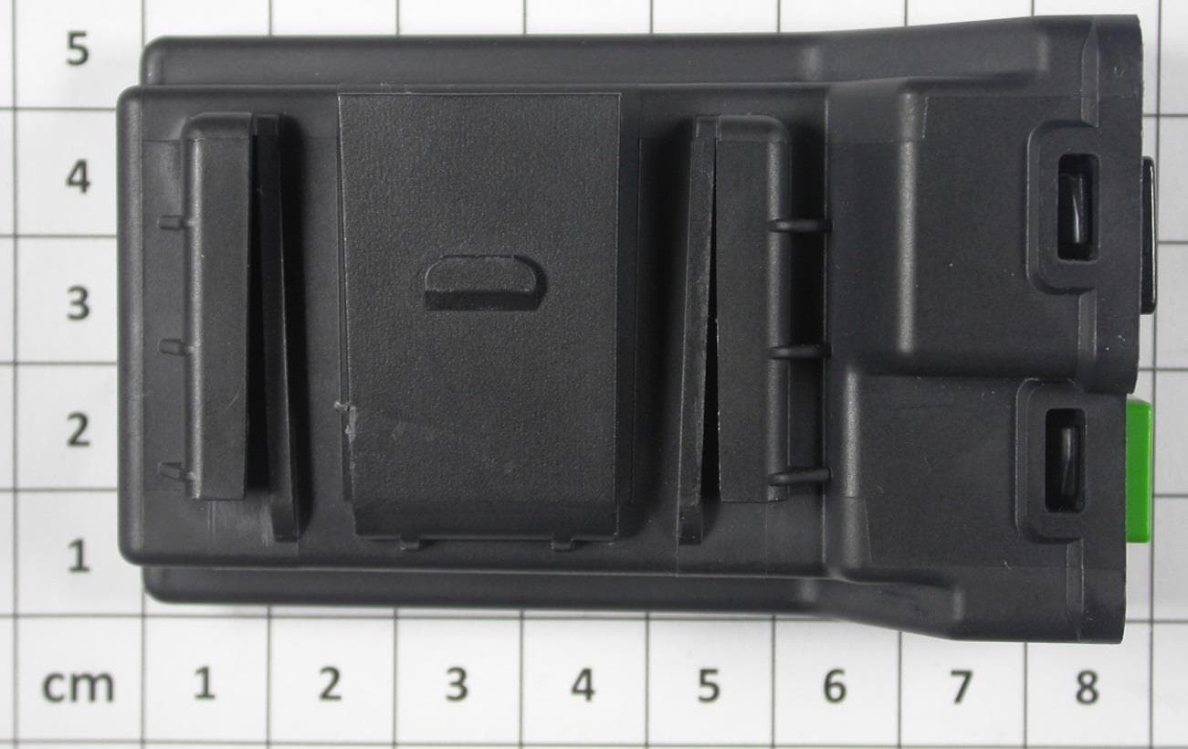
Click to zoom
Application Details
- Equipment Class
- DTS - Digital Transmission System
- Date of Grant
- Feb 05, 2014
- Application Purpose
- Original Equipment
- Date of Application
- Feb 05, 2014
- Equipment Note
- Transceiver for remote vehicle access
- Frequency Range
- 925.99960000 - 926.00050000
- Country
- Germany
Documents & Files
Document Text
Text extracted from the exhibit documents filed with the FCC. Open a document above to read the original.
Cover Letter(s)
1/1 Continental Automotive GmbH |Siemensstr.12, 93055 Regensburg | P.O. Box 100943, 93009 Regensburg | Germany Phone +49 941 790-0 | Fax +49 941 790-4999 | www.continental-corporation.com Chairman of the Supervisory Board: Helmut Matschi | Registered Office: Hannover | Registered Court: Amtsgericht Hannover HRB No. 59424 | VAT ID No.: DE814950663 Executive Board: Georg Sistermanns, Harald Stuhlmann To whom it may concern: We the undersigned, hereby authorize CSA Group Bayern GmbH, Mr. Thomas Ring, Ohmstrasse 1-4, 94342 Strasskirchen, Germany to act on our behalf in all manners relating to application for equipment authorization, including signing of all documents relating to these matters. Any and all acts carried out by CSA Group Bayern GmbH on our behalf shall have the same affect as acts of our own. This authorization is valid until further written notice from Continental Automotive GmbH. Sincerely, Dagmar Kolar Manager RF Homologation Date Your message dated Our reference Your reference December 09, 2013 Corporate Quality and Environment Continental Automotive GmbH, Siemensstr.12, D-93055 Regensburg Federal Communications Commission 7435 Oakland Mills Road Columbia, MD 21046 Dagmar Kolar RF Homologation / QL RBG 43 Phone +49 941 790-6699 Fax +49 941 790-996699 dagmar.kolar@continental- corporation.com
Cover Letter(s)
Continental Automotive GmbH Siemensstr. 12 93055 Regensburg Postfach 100 953 93009 Regensburg Phone +49 941 790-0 Fax +49 941 790-4999 www.continental-corporation.com Registered Office: Hanover Registered Court: Amtsgericht Hanover HRB 59424 General Managers: Gerard Cordonnier, Helmut Matschi, Harald Stuhlmann January 28, 2014 Your message dated Our Reference Your reference Request for Confidentiality Subject: Confidentiality Request for: FCC ID: KR582035100 IC: 7812D-82035100 Pursuant to FCC 47 CRF 0.457(d) and 0.459 and IC RSP-100, Section 10, the applicant requests that a part of the subject FCC application be held confidential. Type of Confidentiality Requested Exhibit Short Term Permanent Block Diagrams Short Term External Photos Short Term Permanent* 1 Internal Photos Short Term Permanent Operation Description/Theory of Operation Short Term Permanent Parts List & Placement/BOM Short Term Permanent Tune-Up Procedure Short Term Permanent Schematics Short Term Test Setup Photos Short Term Permanent* User’s Manual Short Term Permanent Antenna Datasheets 1 - The asterisked items (*) require further justification before permanent confidentiality will be allowed. These also currently require review by the FCC under their Permit-But-Ask policy before the grant is issued and can delay completion of an application. Further justification should be added to the note above. One such example for a potted device would be: “The EUT is FULLY potted using a non-removable epoxy based material. Removal of potting material causes irreparable damage to internal circuitry. See photographs exhibits that outline the device before and after potting.” Dagmar Kolar RF Homologation / QL RBG 43 Tel. +49 941 790-6699 Fax +49 941 790-996699 dagmar.kolar@continental- corporation.com Continental Automotive GbmH – Postfach 10 09 43 – 93009 Regensburg - 2 - *Note: ______(Insert Explanation as Necessary)______ Continental Automotive GmbH has spent substantial effort in developing this product and it is one of the first of its kind in industry. Having the subject information easily available to "competition" would negate the advantage they have achieved by developing this product. Not protecting the details of the design will result in financial hardship. Permanent Confidentiality: The applicant requests the exhibits listed above as permanently confidential be permanently withheld from public review due to materials that contain trade secrets and proprietary information not customarily released to the public. Short-Term Confidentiality: The applicant requests the exhibits selected above as short term confidential be withheld from public view for a period of (0) days from the date of the Grant of Equipment Authorization and prior to marketing. This is to avoid premature release of sensitive information prior to marketing or release of the product to the public. Applicant is also aware that they are responsible to notify ACB in the event information regarding the product or the product is made available to the public. ACB will then release the documents listed above for public disclosure pursuant to FCC Public Notice DA 04-1705. NOTE for Industry Canada Applications: The applicant understands that until such time that IC distinguishes between Short Term and Permanent Confidentiality, either type of marked exhibit above will simply be marked Confidential when submitted to IC. Sincerely, By: Dagmar Kolar Manager RF Homologation
External Photos
- Car roof antenna - 39150-TZ3A-A231-M1: - Car roof antenna - 39150-TZ3A-X021-M1 - Car roof antenna - 39150-TZ3A-A040-M1
ID Label/Location Info
Label Placement
Internal Photos
1.2 Internal views:
Test Report
FCC ID: KR582035100 IC ID: 7812D-82035100 CSA Group Bayern GmbH File No. T36248-04-01HU, page 1 of 51 Ohmstrasse 1-4 94342 STRASSKIRCHEN GERMANY Tel.:+49(0)9424-94810 Fax: ++49(0)9424-9481440 Rev. No. 3.0.2013-10-01 EMI − T E S T R E P O R T - FCC Part 15.247, RSS210 - Test Report No. : T36248-04-01HU 05. February 2014 ______________________________________________________________________________________________ Date of issue Type / Model Name : A2C82035100 Product Description : Transceiver for remote vehicle access Applicant : Continental Automotive GmbH Address : Siemensstr. 12 93055 Regensburg, Germany Manufacturer : Continental Guadalajara México, S.A. de C.V. Address : Camino a la Tijera No.3 45640 Tlajomulco de Zuῇiga, Jalisco, Mexico Licence holder : Continental Automotive GmbH Address : Siemensstr. 12 93055 Regensburg, Germany Test Result according to the standards listed in clause 1 test standards: POSITIVE The test report merely corresponds to the test sample. It is not permitted to copy extracts of these test results without the written permission of the test laboratory. FCC ID: KR582035100 IC ID: 7812D-82035100 CSA Group Bayern GmbH File No. T36248-04-01HU, page 2 of 51 Ohmstrasse 1-4 94342 STRASSKIRCHEN GERMANY Tel.:+49(0)9424-94810 Fax: ++49(0)9424-9481440 Rev. No. 3.0.2013-10-01 Contents 1 T E S T S T A N D A R D S 3 2 S U M M A R Y 4 2.1 Test result summery 4 2.2 General remarks 5 2.3 Final assessment 5 3 E Q U I P M E N T U N D E R T E S T 6 3.1 Photo documentation of the EUT – Detailed photos see attachment A 6 3.2 Power supply system utilised 6 3.3 Short description of the equipment under test (EUT) 6 4 T E S T E N V I R O N M E N T 7 4.1 Address of the test laboratory 7 4.2 Environmental conditions 7 4.3 Statement of the measurement uncertainty 7 4.4 Measurement protocol for FCC and IC 8 5 T E S T C O N D I T I O N S A N D R E S U L T S 10 5.1 Conducted emissions 10 5.2 Emission bandwidth 11 5.3 Occupied bandwidth 17 5.4 Maximum peak conducted output power 22 5.5 Spurious emissions conducted 26 5.7 Spurious emissions radiated 34 5.8 Power spectral density 38 5.9 Maximum permissible exposure (MPE) 44 5.11 Antenna application 47 5.13 Receiver radiated emissions 48 6 U S E D T E S T E Q U I P M E N T A N D A C CE S S O R I E S 51 FCC ID: KR582035100 IC ID: 7812D-82035100 CSA Group Bayern GmbH File No. T36248-04-01HU, page 3 of 51 Ohmstrasse 1-4 94342 STRASSKIRCHEN GERMANY Tel.:+49(0)9424-94810 Fax: ++49(0)9424-9481440 Rev. No. 3.0.2013-10-01 1 T E S T S T A N D A R D S The tests were performed according to following standards: FCC Rules and Regulations Part 15, Subpart A - General (October, 2013) Part 15, Subpart A, Section 15.31 Measurement standards Part 15, Subpart A, Section 15.33 Frequency range of radiated measurements Part 15, Subpart A, Section 15.35 Measurement detector functions and bandwidths FCC Rules and Regulations Part 15 Subpart B - Unintentional Radiators (October, 2013) Part 15, Subpart B, Section 15.107 AC Line conducted emission Class A device Class B device Part 15, Subpart B, Section 15.109 Radiated emission, general requirements FCC Rules and Regulations Part 15, Subpart C - Intentional Radiators (October, 2013) Part 15, Subpart C, Section 15.203 Antenna requirement Part 15, Subpart C, Section 15.204 External radio frequency power amplifiers and antenna modifications Part 15, Subpart C, Section 15.205 Restricted bands of operation Part 15, Subpart C, Section 15.207 Conducted limits Part 15, Subpart C, Section 15.209 Radiated emission limits, general requirements Part 15, Subpart C, Section 15.247 Operation within the bands 902 - 928 MHz, 2400 - 2483.5 MHz and 5725 - 5850 MHz FCC Rules and Regulations Part 1, Subpart I - Procedures Implementing the National Environmental Policy Act of 1969 Part 1, Subpart I, Section 1.1310 Radiofrequency radiation exposure limits Part 1, Subpart 2, Section 2.1093 Radiofrequency radiation exposure evaluation: portable device OET Bulletin 65, 65A, 65B, 65C Edition 97-01, August 1997 – Evaluating Compliance with FCC Guidelines for Human Exposure to Radio Frequency Electromagnetic Fields. ANSI C63.4: 2003 Methods of Measurement of Radio-Noise Emissions from Low- Voltage Electrical and Electronic Equipment in the Range of 9 kHz to 40 GHz. ANSI C95.1: 2005 IEEE Standard for Safety Levels with respect to Human Exposure to Radio Frequency Electromagnetic Fields, 3 kHz to 300 GHz CISPR 16-4-2: 2003 Uncertainty in EMC measurement CISPR 22: 2005 Information technology equipment EN 55022: 2006 KDB 558074 D01 Guidance for performing compliance measurements on DTS operating under Section 15.247, v03r01 of April 9, 2013. FCC ID: KR582035100 IC ID: 7812D-82035100 CSA Group Bayern GmbH File No. T36248-04-01HU, page 4 of 51 Ohmstrasse 1-4 94342 STRASSKIRCHEN GERMANY Tel.:+49(0)9424-94810 Fax: ++49(0)9424-9481440 Rev. No. 3.0.2013-10-01 2 S U M M A R Y 2.1 Test result summery FCC Rule Part RSS Rule Part Description Result 15.207(a) RSS Gen, 7.2.4. AC power line conducted emissions passed 15.247(a)(2) RSS210, A8.2(a) -6 dB EBW passed 15.247(b)(3) RSS-210, A8.4(4) Peak power passed 15.247(d) RSS-210, A8.5 Out-of-band emission, radiated passed 15.247(d) RSS-Gen, 7.2.2 Emissions in restricted bands passed 15.247(e) RSS-210, A8.2(b) PSD passed 15.35(c) RSS-Gen, 4.5 Pulsed operation not applicable 15.247(i) RSS 102, 2.5.2 MPE passed 15.247(b)(4) RSS-Gen, 7.1.2 Antenna requirement passed 15.107 RSS Gen, 7.2.4. AC power line conducted emissions passed 15.109(a) RSS-Gen, 6.1 Receiver spurious emissions, radiated passed RSS-Gen, 7.2.6 Transmitter frequency stability not applicable RSS-Gen, 4.6.1 99 % Bandwidth passed OET Bulletin 65 RSS102, 3.2 Co-location, Co-transmission not applicable The mentioned RSS Rule Parts in the above table are related to: RSS Gen, Issue 3, December 2010 RSS 210, Issue 8, December 2010 RSS 102, Issue 4, March 2010 FCC ID: KR582035100 IC ID: 7812D-82035100 CSA Group Bayern GmbH File No. T36248-04-0…
Text truncated - open the document above for the full version.
Test Report
Attachment A to File No.: T36248-04 1 P h o t o d o c u m e n t a t i o n o f t h e E U T 1.1 External views: - Test setup: 1.2 Internal views: - Car roof antenna - 39150-TZ3A-A231-M1: - Car roof antenna - 39150-TZ3A-X021-M1 - Car roof antenna - 39150-TZ3A-A040-M1
Test Setup Photos
FCC ID: KR582035100 IC ID: 7812D-82035100 CSA Group Bayern GmbH File No. T36248-04-01HU, page 11 of 52 Ohmstrasse 1-4 94342 STRASSKIRCHEN GERMANY Tel.:+49(0)9424-94810 Fax: ++49(0)9424-9481440 Rev. No. 3.0.2013-10-01 5.2 Emission bandwidth For test instruments and accessories used see section 6 Part MB. 5.2.1 Description of the test location Test location: AREA4 5.2.2 Photo documentation of the test set-up 5.2.3 Applicable standard According to FCC Part 15, Section 15.247(a)(2): Systems using digital modulation techniques may operate in the 902 - 928 MHz, 2400 – 2483.5 MHz and 5725 – 5850 MHz bands. The minimum 6 dB bandwidth shall be at least 500 kHz. 5.2.4 Description of Measurement The bandwidth was measured at an amplitude level reduced from the reference level of a modulated channel by a ratio of -6 dB. The reference level is the level of the highest signal amplitude observed at the transmitter at either the fundamental frequency or the first order modulation products in all typical modes of operation, including the unmodulated carrier, even if atypical. An alternative is to use the bandwidth measurement of the analyser. FCC ID: KR582035100 IC ID: 7812D-82035100 CSA Group Bayern GmbH File No. T36248-04-01HU, page 17 of 52 Ohmstrasse 1-4 94342 STRASSKIRCHEN GERMANY Tel.:+49(0)9424-94810 Fax: ++49(0)9424-9481440 Rev. No. 3.0.2013-10-01 5.3 Occupied bandwidth For test instruments and accessories used see section 6 Part MB. 5.3.1 Description of the test location Test location: AREA4 5.3.2 Photo documentation of the test set-up 5.3.1 Applicable standard According to RSS-Gen, 4.6.1: When an occupied bandwidth value is not specified in the applicable RSS, the transmitted signal bandwidth to be reported is to be its 99 % emission bandwidth, as calculated or measured. 5.3.2 Description of Measurement The bandwidth was measured with the function “bandwidth measurement” of the spectrum analyser. The EUT is connected via suitable attenuator at the spectrum analyser. The measurement is repeated for every different modulation standard of the EUT and recorded. FCC ID: KR582035100 IC ID: 7812D-82035100 CSA Group Bayern GmbH File No. T36248-04-01HU, page 22 of 52 Ohmstrasse 1-4 94342 STRASSKIRCHEN GERMANY Tel.:+49(0)9424-94810 Fax: ++49(0)9424-9481440 Rev. No. 3.0.2013-10-01 5.4 Maximum peak conducted output power For test instruments and accessories used see section 6 Part CPC 3. 5.4.1 Description of the test location Test location: AREA4 5.4.2 Photo documentation of the test set-up 5.4.3 Applicable standard According to FCC Part 15, Section 15.247(b)(3): For systems using digital modulation in the 902 – 928 MHz, 2400-2483.5 MHz and 5725 – 5850 MHz bands, the maximum peak output power of the transmitter shall not exceed 1 Watt. The limit is based on transmitting antennas of directional gain that do not exceed 6 dBi. 5.4.4 Description of Measurement The EuT was fixed mounted on the receiving antenna of the spectrum analyzer to find out the maximum power. An analyzer offset was tried to see the compliance to the measured radiated value. The transmitter output was directly connected to the spectrum analyzer. The center frequency of the spectrum analyzer is set to the fundamental frequency. The span of the spectrum analyzer should be larger than the emission bandwidth (EBW). The channel bandwidth has been set to EBW. With peak detector and power mode “Max Hold” the result is the summed maximum output power of the EBW. FCC ID: KR582035100 IC ID: 7812D-82035100 CSA Group Bayern GmbH File No. T36248-04-01HU, page 26 of 52 Ohmstrasse 1-4 94342 STRASSKIRCHEN GERMANY Tel.:+49(0)9424-94810 Fax: ++49(0)9424-9481440 Rev. No. 3.0.2013-10-01 5.5 Spurious emissions conducted For test instruments and accessories used see section 6 Part SEC 1, SEC 2 and SEC 3. 5.5.1 Description of the test location Test location: Anechoic chamber 2 5.5.2 Photo documentation of the test set-up 5.5.3 Applicable standard According to FCC Part 15C, Section 15.247(d): In any 100 kHz bandwidth outside the frequency band 902 to 928 MHz, the digitally modulated radio frequency power that is produced by the intentional radiator shall be at least 20 dB below that in the 100 kHz bandwidth within the band that contains the highest level of the desired power, based on either an RF conducted or an radiated measurement. Attenuation below the general limits specified in Section 15.209(a) is not required. In addition, radiated emissions which fall in the restricted bands, as defined in Section 15.205(a), must also comply with the radiated emission limit specified in Section 15.209(a). 5.5.4 Description of measurement A spectrum analyzer is connected to the output of the transmitter while EUT was operating in transmit mode at the assigned frequency. FCC ID: KR582035100 IC ID: 7812D-82035100 CSA Group Bayern GmbH File No. T36248-04-01HU, page 34 of 52 Ohmstrasse 1-4 94342 STRASSKIRCHEN GERMANY Tel.:+49(0)9424-94810 Fax: ++49(0)9424-9481440 Rev. No. 3.0.2013-10-01 5.7 Spurious emissions radiated For test instruments and accessories used see section 6 Part SER 1, SER 2, SER 3. 5.7.1 Description of the test location Test location: OATS 1 Test location: Anechoic chamber 2 Test distance: 3 m 5.7.2 Photo documentation of the test set-up Open area test site FCC ID: KR582035100 IC ID: 7812D-82035100 CSA Group Bayern GmbH File No. T36248-04-01HU, page 35 of 52 Ohmstrasse 1-4 94342 STRASSKIRCHEN GERMANY Tel.:+49(0)9424-94810 Fax: ++49(0)9424-9481440 Rev. No. 3.0.2013-10-01 Anechoic chamber 5.7.3 Applicable standard According to FCC Part 15, Section 15.247(d): In any 100 kHz bandwidth outside the frequency bands 902 – 928 MHz, 2400 – 2483.50 MHz and 5725 – 5850 MHz, the digitally modulated radio frequency power that is produced by the intentional radiator shall be at least 20 dB below that in the 100 kHz bandwidth within the band that contains the highest level of the desired power, based on either an RF conducted or an radiated mea…
Text truncated - open the document above for the full version.
Contact Information
Applicant
Thomas Heselberger
Technical Contact
Test Firm
CSA Group Bayern GmbHFrank Scharnowski
Technical Specifications
| # | Rule Parts | Frequency Range | Power Output |
|---|---|---|---|
| 1 | 15C | 925.9996 MHz - 926.0005 MHz | 50.00 mW |
Other Applications from Continental Automotive Technologies GmbH
KR5FERKEY25
Jul 06, 2026Romete Car Key
Equipment Class
DSC - Part 15 Security/Remote Control TransmitterKR5KAM01
May 12, 2026KAM (Key Authentication Module)
Equipment Class
DCD - Part 15 Low Power Transmitter Below 1705 kHzKR5HFM501
Apr 29, 2026Hand Free Module
Equipment Class
DCD - Part 15 Low Power Transmitter Below 1705 kHzKR5TXPZ6
Mar 05, 2026Radio Frequency Transmitter
Equipment Class
DSC - Part 15 Security/Remote Control TransmitterKR5TXPZ5
Mar 05, 2026TXPZ5
Equipment Class
DSC - Part 15 Security/Remote Control Transmitter