KR5A2C81494900Radio Frequency Transmitter for RKE
Continental Automotive Technologies GmbH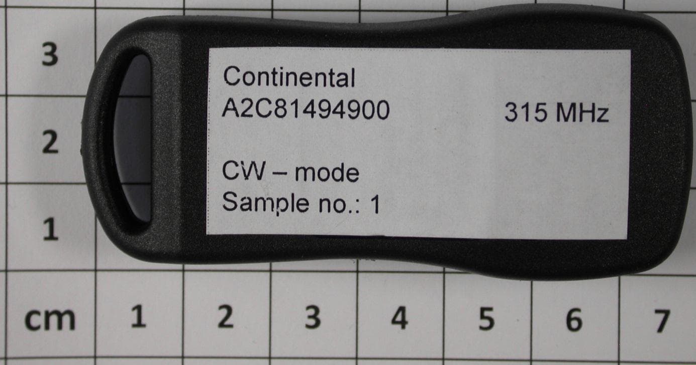
Click to zoom
Application Details
- Equipment Class
- DSC - Part 15 Security/Remote Control Transmitter
- Date of Grant
- Aug 29, 2012
- Application Purpose
- Original Equipment
- Date of Application
- Aug 29, 2012
- Equipment Note
- Radio Frequency Transmitter for RKE
- Frequency Range
- 315.00000000 - 315.00000000
- Country
- Germany
Documents & Files
Document Text
Text extracted from the exhibit documents filed with the FCC. Open a document above to read the original.
Users Manual
page 1 of 4 Functional Description / User Manual of Continental Remote Control System A2C81494900 page 2 of 4 General description of the RF transmitter The RF (radio frequency) remote control system consists of a RF transmitter and a RF receiver mounted within the control unit. The described system is a radio-frequency remote control for central doors locking / unlocking, trunk release and Panic activity of an automotive vehicle. System Operation: Remote keyless entry function is provided by the RF system of the Rx and the RKE transmitter. The operation of these functions are as follows: Remote keyless Entry: The RKE transmitter operate at 315 MHz. ASK modulated data signal is transmitted to the Rx which receives the encrypted RF signal. Then, it send the data of the signal to corresponding the host Body control module through the communication line. This transmitter is used to transmit an information for locking or unlocking of the vehicle by an unidirectional RF transmission line for normal remote operation by pressing a button. In general the following functions are provided: - Lock the car - Unlock the car - Unlock the trunk of the car - Panic RF Key Identifier Start code RF emission SRx receiver Host BCM Communication Line page 3 of 4 Typical usage pattern RKE transmitter 30 lock / unlock operations in 24 hours with a typical transmission duration of 270 milliseconds 1.25 lock / unlock operations / hour Transmitter ON 0.3375 seconds / hour Transmitter OFF 3,599.6625 seconds / hour Duty Cycle: T ON / T (ON+OFF) x 100% = 0.3375 / 3,600 x 100 % = 0,009 % The Modulation used is ASK Manchester coded , therefore the radiated energy during one telegram is ON only a half of the time of the telegram this means and AVG factor of 20Log(1/2)= -6dB Variants: Model Description A2C81494900 Transmitter 4button ASK 315MHz Block diagram page 4 of 4 Technical data transmitter Carrier frequency: 315.00MHz 150kHz Output power : < 75.6dBuV/m @3m Modulation: A SK Method of frequency generation: SAW Resonator Number of channels: 1 Supply voltage: 3 V Battery type: lithium, CR 2025 NOTE: Changes or modifications not expressly approved by the manufacturer could void the user ́s authority to operate the equipment. This device complies with Part 15 of the FCC Rules. Operation is subject to the following two conditions: (1) this device may not cause harmful interference, and (2) this device must accept any interference received, including interference that may cause undesired operation Label design Continental A2C81494900 FCC ID: KR5A2C81494900
External Photos
Attachment A to File No.: T36124-01 1 P h o t o d o c u m e n t a t i o n o f t h e E U T 1.1 External views – original sample: 1.3 External views – modified sample:
Internal Photos
1.2 Internal views – original sample: 1.4 Internal views – modified sample:
Test Report
FCC ID: KR5A2C81494900 mikes-testingpartners gmbh File No. T36124-01-00HU, page 1 of 28 Ohmstrasse 2-4 94342 STRASSKIRCHEN GERMANY Tel.:+49(0)9424-94810 Fax: +49(0)9424-9481240 Rev. No. 1.2, 9.9.2010 EMI − T E S T R E P O R T - FCC Part 15.231 - Test Report No. : T36124-01-00HU 09. August 2012 ______________________________________________________________________________________________ Date of issue Type / Model Name : A2C81494900 Product Description : Radio frequency Transmitter for RKE Applicant : Continental Automotive GmbH Address : Siemensstraße 12 93055 Regensburg, Germany Manufacturer : Continental Automotive Changchun Co., Ltd Address : Wuhan Avenue 1981 130033 Changchun, P. R. China Licence holder : Continental Automotive GmbH Address : Siemensstraße 12 93055 Regensburg, Germany Test Result according to the standards listed in clause 1 test standards: POSITIVE The test report merely corresponds to the test sample. It is not permitted to copy extracts of these test results without the written permission of the test laboratory. FCC ID: KR5A2C81494900 mikes-testingpartners gmbh File No. T36124-01-00HU, page 2 of 28 Ohmstrasse 2-4 94342 STRASSKIRCHEN GERMANY Tel.:+49(0)9424-94810 Fax: +49(0)9424-9481240 Rev. No. 1.2, 9.9.2010 Contents 1 T E S T S T A N D A R D S 3 2 S U M M A R Y 4 3 E Q U I P M E N T U N D E R T E S T 5 3.1 Photo documentation of the EUT – See Attachment A 5 3.2 Power supply system utilised 6 3.3 Short description of the Equipment under Test (EUT) 6 4 T E S T E N V I R O N M E N T 7 4.1 Address of the test laboratory 7 4.2 Environmental conditions 7 4.3 Statement of the measurement uncertainty 7 4.4 Measurement Protocol for FCC, VCCI and AUSTEL 7 5 T E ST C O N D I T I O N S A N D R E S U L T S 9 5.1 Conducted emissions 9 5.2 Field strength of the fundamental wave 10 5.3 Spurious emissions (magnetic field) 9 kHz – 30 MHz 12 5.4 Spurious emissions radiated (electric field) 14 5.5 Correction for pulse operation (duty cycle) 18 5.6 Emission bandwidth 22 5.7 Signal deactivation 25 6 U S E D T E S T E Q U I P M E N T A N D A C C E S S O R I E S 28 FCC ID: KR5A2C81494900 mikes-testingpartners gmbh File No. T36124-01-00HU, page 3 of 28 Ohmstrasse 2-4 94342 STRASSKIRCHEN GERMANY Tel.:+49(0)9424-94810 Fax: +49(0)9424-9481240 Rev. No. 1.2, 9.9.2010 1 T E S T S T A N D A R D S The tests were performed according to following standards: FCC Rules and Regulations Part 15 Subpart C - Intentional Radiators (October, 2011) Part 15, Subpart C, Section 15.231 Periodic operation in the band 40.66-40.70 MHz and above 70 MHz §15.231(a) Signal deactivation §15.231(b) Radiated emissions, Fundamental & Harmonics §15.231(c) Emission Bandwidth Part 15, Subpart C, Section 15.35(c) Correction for Pulse Operation (Duty Cycle) Part 15, Subpart C, Section 15.207(a) AC Line conducted emissions Part 15, Subpart C, Section 15.209(a) Radiated emissions, general requirements FCC Rules and Regulations Part 15 Subpart B - Intentional Radiators (October, 2011) Part 15, Subpart B, Section 15.107(a) AC Line conducted emissions Part 15, Subpart B, Section 15.109(a) Radiated emissions, general requirements ANSI C63.4: 2003 Methods of Measurement of Radio-Noise Emissions from Low- Voltage Electrical and Electronic Equipment in the Range of 9 kHz to 40 GHz. ANSI C95.1:1992 IEEE Standard for Safety Levels with respect to Human Exposure to Radio Frequency Electromagnetic Fields, 3 kHz to 300 GHz CISPR 16-4-2: 2003 Uncertainty in EMC measurement FCC ID: KR5A2C81494900 mikes-testingpartners gmbh File No. T36124-01-00HU, page 4 of 28 Ohmstrasse 2-4 94342 STRASSKIRCHEN GERMANY Tel.:+49(0)9424-94810 Fax: +49(0)9424-9481240 Rev. No. 1.2, 9.9.2010 2 S U M M A R Y GENERAL REMARKS: All radiated tests have been performed on a modified sample which are in continuous transmitting mode. The other mesurements have been performed on a sample which are in original state. FINAL ASSESSMENT: The equipment under test fulfills the EMI requirements cited in clause 1 test standards. Date of receipt of test sample : acc. to storage records Testing commenced on : 06. August 2012 Testing concluded on : 09. August 2012 Checked by: Tested by: Harald Buchwald Dipl.-Ing.(FH) Manager: EMC Markus Huber FCC ID: KR5A2C81494900 mikes-testingpartners gmbh File No. T36124-01-00HU, page 5 of 28 Ohmstrasse 2-4 94342 STRASSKIRCHEN GERMANY Tel.:+49(0)9424-94810 Fax: +49(0)9424-9481240 Rev. No. 1.2, 9.9.2010 3 E Q U I P M E N T U N D E R T E S T 3.1 Photo documentation of the EUT – See Attachment A FCC ID: KR5A2C81494900 mikes-testingpartners gmbh File No. T36124-01-00HU, page 6 of 28 Ohmstrasse 2-4 94342 STRASSKIRCHEN GERMANY Tel.:+49(0)9424-94810 Fax: +49(0)9424-9481240 Rev. No. 1.2, 9.9.2010 3.2 Power supply system utilised Power supply voltage: 3.0 V / DC (Battery type: CR2032) 3.3 Short description of the Equipment under Test (EUT) The EuT is a transmitter of a keyless entry system for vehicles. Number of tested samples: 2 Serial number: see Photo documentation of the EuT under Point 3 / Equipment Under Test EUT operation mode: The equipment under test was operated during the measurement under the following conditions: - Tx mode at 315 MHz - Cont. Tx mode at 315 MHz - EUT configuration: The following peripheral devices and interface cables were connected during the measurements: - Model : - Model : - Model : - Model : - Model : - Model : FCC ID: KR5A2C81494900 mikes-testingpartners gmbh File No. T36124-01-00HU, page 7 of 28 Ohmstrasse 2-4 94342 STRASSKIRCHEN GERMANY Tel.:+49(0)9424-94810 Fax: +49(0)9424-9481240 Rev. No. 1.2, 9.9.2010 4 T E S T E N V I R O N M E N T 4.1 Address of the test laboratory mikes-testingpartners gmbh Ohmstrasse 2-4 94342 STRASSKIRCHEN GERMANY 4.2 Environmental conditions During the measurement the environmental conditions were within the listed ranges: Temperature: 15-35 ° C Humidity: 30-60 % Atmospheric pressure: 86-106 kPa 4.3 Statement of the measurement uncertainty The data an…
Text truncated - open the document above for the full version.
Test Report
Attachment A to File No.: T36124-01 1 P h o t o d o c u m e n t a t i o n o f t h e E U T 1.1 External views – original sample: 1.2 Internal views – original sample: 1.3 External views – modified sample: 1.4 Internal views – modified sample:
Test Setup Photos
FCC ID: KR5A2C81494900 mikes-testingpartners gmbh File No. T36124-01-00HU, page 10 of 28 Ohmstrasse 2-4 94342 STRASSKIRCHEN GERMANY Tel.:+49(0)9424-94810 Fax: +49(0)9424-9481240 Rev. No. 1.2, 9.9.2010 5.2 Field strength of the fundamental wave For test instruments and accessories used see section 6 Part CPR 2. 5.2.1 Description of the test location Test location: OATS1 Test distance: 3 metres 5.2.2 Photo documentation of the test set-up 5.2.1 Applicable standard According to FCC Part 15C, Section 15.231(b): The field strength of emissions from intentional radiators shall not exceed the effective field strength limits. 5.2.2 Description of Measurement The radiated power of the fundamental wave from the EUT is measured in the frequency range of 30 to 1000 MHz using a tuned receiver and appropriate broadband linearly polarized antennas. Measurements between 30 MHz and 1000 MHz are made with 120 kHz/6 dB bandwidth and quasi-peak detection. Table top equipment is placed on a 1.0 X 1.5 metres non-conducting table 80 centimetres above the ground plane. Floor standing equipment is placed directly on the turntable/ground plane. The set up of the EUT will be in accordance to ANSI C63.4. The Interface cables that are closer than 40 centimetres to the ground plane are bundled in the centre in a serpentine fashion so they are at least 40 centimetres from the ground plane. Cables to simulators/testers (if used in this test) are routed through the centre of the table and to a screen room located outside the test area. The antenna was positioned 3, 10 or 30 metres horizontally from the EUT. To locate maximum emissions from the test sample the antenna is varied in height from 1 to 4 metres, measurement scans are made in horizontal and vertical antenna polarization’s and the EUT is rotated 360 degrees. The resolution bandwidth during the measurement is as follows: 30 MHz – 1000 MHz: RBW: 120 kHz FCC ID: KR5A2C81494900 mikes-testingpartners gmbh File No. T36124-01-00HU, page 12 of 28 Ohmstrasse 2-4 94342 STRASSKIRCHEN GERMANY Tel.:+49(0)9424-94810 Fax: +49(0)9424-9481240 Rev. No. 1.2, 9.9.2010 5.3 Spurious emissions (magnetic field) 9 kHz – 30 MHz For test instruments and accessories used see section 6 Part SER 1. 5.3.1 Description of the test location Test location: OATS1 Test distance: 3 metres 5.3.2 Photo documentation of the test set-up 5.3.3 Applicable standard According to FCC Part 15C, Section 15.209: The emissions from intentional radiators shall not exceed the effective field strength limits. 5.3.4 Description of Measurement The magnetic field strength from the EUT will be measured on an open area test site in the frequency range of 9 kHz to 30 MHz using a tuned receiver and a shielded loop antenna. The set up of the Equipment under test will be in accordance to ANSI C63.4. The antenna was positioned 3, 10 or 30 meters horizontally from the EUT. Measurements have been made in all three orthogonal axes and the shielded loop antenna was rotated to locate the maximum of the emissions. In the case where larger measuring distances are required the results will extrapolated based on the values measured on the closer distances according to Section 15.31(f)(2)(2). The final measurement will be performed with an EMI Receiver set to Quasi Peak detector except for the frequency bands 9 kHz to 90 kHz and 110 to 490 kHz where an average detector will be used according to Section 15.209(d)(2). FCC ID: KR5A2C81494900 mikes-testingpartners gmbh File No. T36124-01-00HU, page 14 of 28 Ohmstrasse 2-4 94342 STRASSKIRCHEN GERMANY Tel.:+49(0)9424-94810 Fax: +49(0)9424-9481240 Rev. No. 1.2, 9.9.2010 5.4 Spurious emissions radiated (electric field) For test instruments and accessories used see section 6 Part SER 2, SER 3. 5.4.1 Description of the test location Test location: OATS1 Anechoic Chamber A2 Test distance: 3 metres 5.4.2 Photo documentation of the test set-up FCC ID: KR5A2C81494900 mikes-testingpartners gmbh File No. T36124-01-00HU, page 18 of 28 Ohmstrasse 2-4 94342 STRASSKIRCHEN GERMANY Tel.:+49(0)9424-94810 Fax: +49(0)9424-9481240 Rev. No. 1.2, 9.9.2010 5.5 Correction for pulse operation (duty cycle) For test instruments and accessories used see section 6 Part DC. 5.5.1 Description of the test location Test location: AREA4 5.5.2 Photo documentation of the test set-up 5.5.3 Applicable standard According to FCC Part 15C, Section 15.35(c): The emissions from intentional radiators shall not exceed the effective field strength limits. 5.5.4 Test result The Duty cycle factor (dB) is calculated applying the following formula: KE= 20 log ((tiB)/100) KE: pulse operation correction factor (dB) tiB pulse duration for one pulse (ms) Maximum transmitting duration in every 100ms period: KE= 20 log ((6.0*)/100) = -4.44 dB * max. Tx on time within a 100 ms time period is 100 x 0.6 ms. Remarks: The pulse train (Tw) exceeds 100 ms, therefore the duty cycle have been calculated by averaging the sum of the pulse widths over the 100 ms width with the highest average value. For detailed results, please see the test protocol below. FCC ID: KR5A2C81494900 mikes-testingpartners gmbh File No. T36124-01-00HU, page 22 of 28 Ohmstrasse 2-4 94342 STRASSKIRCHEN GERMANY Tel.:+49(0)9424-94810 Fax: +49(0)9424-9481240 Rev. No. 1.2, 9.9.2010 5.6 Emission bandwidth For test instruments and accessories used see section 6 Part MB. 5.6.1 Description of the test location Test location: AREA4 5.6.2 Photo documentation of the test set-up 5.6.3 Applicable standard According to FCC Part 15C, Section 15.231(c): The bandwidth of the emission shall not exceed the effective limits. 5.6.4 Description of Measurement The measurement was performed conducted with intentional modulation using a spectrum analyser. The analyser span was set wide enough to capture the most of the power envelope of the signal. The function “20-dB-down” is used to determine the BW. For an overview on the adjacent restricted bands the span was set as wid…
Text truncated - open the document above for the full version.
Contact Information
Applicant
Thomas Heselberger
Technical Contact
Test Firm
CSA Group Bayern GmbHThomas Weise
Technical Specifications
| # | Rule Parts | Frequency Range | Power Output |
|---|---|---|---|
| 1 | 15.231 | 315 MHz - 315 MHz | - |
Other Applications from Continental Automotive Technologies GmbH
KR5FERKEY25
Jul 06, 2026Romete Car Key
Equipment Class
DSC - Part 15 Security/Remote Control TransmitterKR5KAM01
May 12, 2026KAM (Key Authentication Module)
Equipment Class
DCD - Part 15 Low Power Transmitter Below 1705 kHzKR5HFM501
Apr 29, 2026Hand Free Module
Equipment Class
DCD - Part 15 Low Power Transmitter Below 1705 kHzKR5TXPZ6
Mar 05, 2026Radio Frequency Transmitter
Equipment Class
DSC - Part 15 Security/Remote Control TransmitterKR5TXPZ5
Mar 05, 2026TXPZ5
Equipment Class
DSC - Part 15 Security/Remote Control Transmitter