KR5RENX5220IMSY1Safety Alarms
Continental Automotive Technologies GmbH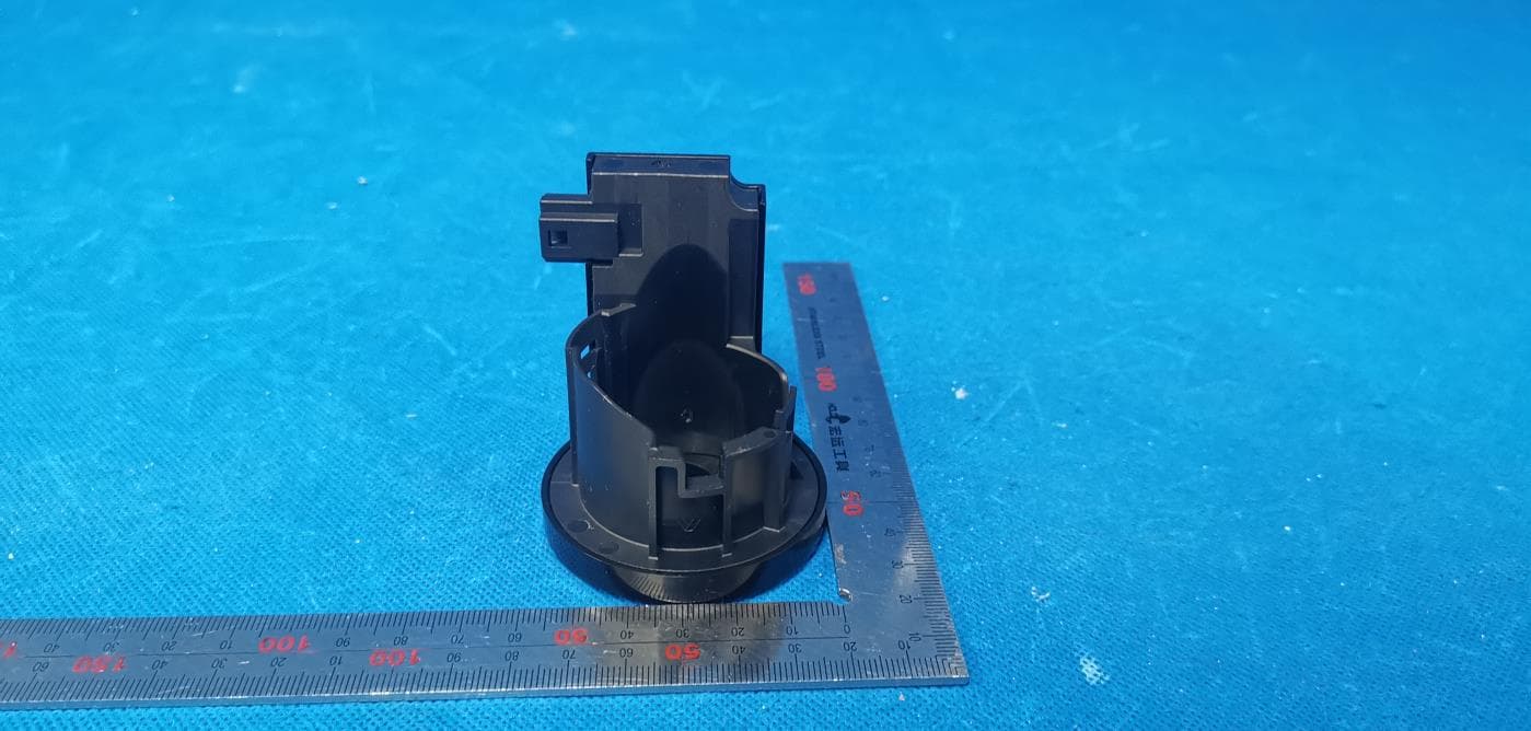
Click to zoom
Application Details
- Equipment Class
- DCD - Part 15 Low Power Transmitter Below 1705 kHz
- Date of Grant
- May 05, 2021
- Application Purpose
- Original Equipment
- Date of Application
- May 05, 2021
- Equipment Note
- Safety Alarms
- Frequency Range
- 0.12500000 - 0.12500000
- Country
- Germany
Documents & Files
Document Text
Text extracted from the exhibit documents filed with the FCC. Open a document above to read the original.
Users Manual
Page: 1 of 3 Functional Description of the Continental Immobilizer REN_X52_20_IMSY-1 Page: 2 of 3 1. SYSTEM OVERVIEW The immobilizer active antenna is suited to be used in combination with potentially two [X52] BCMs (one from Continental and one from CK) and 1 key module from Renault. System integration with competitor product is not assumed by Continental. Validation for additional combinations can be quoted upon request. The whole immobilizer function is accomplished by the mutual authentication between key and BCM while the active antenna is playing a role of charging transponder in key and data modulation (demodulation) in the communication path. The typical immobilizer system with active antenna can be referenced as below: Magnetic field generation: The active antenna contains base station for driven antenna coil which generates the LF field for charging transponder as well as carrying the modulated data. Serial communication with BCM: The active antenna is connected to BCM via synchronous serial link. LF communication data is converted to baseband signals by active antenna and transmitted in half-duplex mode between transponder and BCM on this interface. The component of IMMO_ANT is to be installed on Vehicle lockset, the IMMO_ANT will be driven by BCM to generate magnetic filed which can charge TxP and works as carrier of data transition. In Renault_X52_IMMO vehicle IMMO_ANT has no function of illumination. The immobilizer circuit contains a voltage regulator, a serial interface, a base station IC and an LF antenna. The serial interface is the communication interface for the communication with the BCM. The BCM sends the data for initialization and Page: 3 of 3 authentication to the Base station IC. The active antenna contains the ABIC1 immobilizer base station IC, a ceramic resonator for clock generation, and a voltage regulator for stabilization of power input.It needs to be connected to the BCM for the communication function as well as to battery supply and ground. The Base station IC generates the signals for the transmission to the transponder in the key and drives the antenna. After transmission the base station IC receives the answer from the transponder and sends the answer to the BCM. The software in the BCM controls the complete communication. 2. Product Characteristics Service voltage 7V - 16V Overvoltage protection (jump start) 24V (1 min) Reserve voltage protection (overvoltage) 18V (1 hour) Active current <150 mA Quiescent current < 500uA LF Antenna frequency 125 KHz Page: 4 of 3 LF Antenna normal operating voltage 90 ~ 135 Vpp LF Antenna inductance(with lock) 440 μH LF Antenna quality factor(with lock) >= 10 LF antenna/TxP coupling factor ≥ 2% Rated voltage 7V - 16V Rated current <150 mA Maximum operating temperature -40 C to +85C Maximum altitude 5000m 3. Block Diagram This device complies with part 15 of the FCC Rules. Operation is subject to the following two conditions: (1) This device may not cause harmful interference, and (2) this device must accept any interference received, including interference that may cause undesired operation. FCC statement This equipment has been tested and found to comply with the limits for a Class B digital device, pursuant to Part 15 of the FCC Rules. These limits are designed to provide reasonable protection against harmful interference in a residential installation. This equipment generates, uses and can radiate radio frequency energy and, if not installed and used in accordance with the instructions, may cause harmful interference to radio communications. However, there is no guarantee that interference will not occur in a particular installation. ·If this equipment does cause harmful interference to radio or television reception, which can be determined by turning the equipment off and on, the user is encouraged to try to correct the interference by one or more of the following measures: —Reorient or relocate the receiving antenna. —Increase the separation between the equipment and receiver. —Connect the equipment into an outlet on a circuit different from that to which the receiver is connected. —Consult the dealer or an experienced radio/TV technician for help. RF exposure warning ·The equipment complies with FCC RF exposure limits set forth for an uncontrolled environment. The equipment must not be co-located or operating in conjunction with any other antenna or transmitter. NOTE: Any changes or modifications not expressly approved by the grantee of this device could void the user's authority to operate the equipment.
Cover Letter(s)
Continental Automotive GmbH Siemensstrasse 12 SV C TS RBG EMC-Laboratory Regensburg Germany 102920 – 13 Authority to Act as Agent Date: May 6, 2021 American Certification Body, Inc. 6731 Whittier Avenue Suite C110 McLean, VA 22101 To Whom It May Concern: ______( DEKRA Testing and Certification (Suzhou) Co., Ltd.)______ is authorized to act on our behalf, until otherwise notified, for applications to American Certification Body, Inc. (ACB). We certify that we are not subject to denial of federal benefits, that includes FCC benefits, pursuant to Section 5301 of the Anti-Drug Abuse Act of 1988, 21 U.S.C. 862. Further, no party, as defined in 47 CFR 1.2002 (b), to the application is subject to denial of federal benefits, that includes FCC benefits. We also declare that the information provided to the FCC is true and correct to the best of our knowledge (47 CFR 2.911(d)) and we have been informed of the grantee responsibilities (47 CFR 2.909) with regard to certified equipment. Thank you, Agency Agreement Expiration Date: _____(Typically 8 – 12 months)_____ By: __________________________ ________ Dagmar Kolar ____ (Signature 1 ) (Print name) Title: ______ Type approval employee ______ On behalf of: _______ Continental Automotive GmbH ________ (Company Name) Telephone: _____ 49-941-790-6699 _____ 1 - Must be signed by applicant contact given for applicant on the FCC site, or by the authorized agent if an appropriate authorized agent letter has been provided. Letters should be placed on appropriate letterhead. Continental Automotive GmbH Siemensstrasse 12 SV C TS RBG EMC-Laboratory Regensburg Germany 102920 – 13 Request for Confidentiality Date: May 6, 2021 Subject: Confidentiality Request for: ______FCC ID: KR5RENX5220IMSY1_____ Pursuant to FCC 47 CFR 0.457(d) and 0.459 and IC RSP-100, Section 12.4, the applicant requests that a part of the subject FCC application be held confidential. Type of Confidentiality Requested Exhibit ☐ Short Term ☒ Permanent Block Diagrams ☐ Short Term External Photos ☐ Short Term ☐ Permanent * 2 Internal Photos ☐ Short Term ☒ Permanent Operation Description/Theory of Operation ☐ Short Term ☐ Permanent Parts List & Placement/BOM ☐ Short Term ☐ Permanent Tune-Up Procedure ☐ Short Term ☒ Permanent Schematics ☐ Short Term Test Setup Photos ☐ Short Term ☐ Permanent * 3 User’s Manual ______( Continental Automotive GmbH)______ has spent substantial effort in developing this product and it is one of the first of its kind in industry. Having the subject information easily available to "competition" would negate the advantage they have achieved by developing this product. Not protecting the details of the design will result in financial hardship. Permanent Confidentiality: The applicant requests the exhibits listed above as permanently confidential be permanently withheld from public review due to materials that contain trade secrets and proprietary information not customarily released to the public. Short-Term Confidentiality: The applicant requests the exhibits selected above as short term confidential be withheld from public view for a period of ___(specify number of days not to exceed 180) 3 ___ days from the date of the Grant of Equipment Authorization and prior to marketing. This is to avoid premature release of sensitive information prior to marketing or release of the product to the public. Applicant is also aware that they are responsible to notify ACB in the event information regarding the product or the product is made available to the public before the requested period has expired. ACB will then release the documents listed above for public disclosure pursuant to FCC Public Notice DA 04-1705. NOTE for Industry Canada Applications: IC currently only distinguishes Permanent Confidentiality exhibits as shown above. Short Term confidentiality is not considered applicable to IC applications. Sincerely, By: __________________________ ________ Dagmar Kolar ________________ (Signature/Title 4 ) (Print name) 2 - The asterisked items (*) require further information to be provided to ACB before permanent confidentiality will be extended to these exhibits. Please refer to FCC KDB 726920 and the specific Document link for D01 found at: https://apps.fcc.gov/oetcf/kdb/forms/FTSSearchResultPage.cfm?switch=P&id=41731 and review section II, 3) regarding specific information that must accompany these requests. 3 - Please refer to http://acbcert.com/documents/misc-docs/Memo-Short-Term-Vs-Standard-Confidentiality.pdf for complete details. 4 - Must be signed by applicant contact given for applicant on the FCC site, or by the authorized agent if an appropriate authorized agent letter has been provided. Letters should be placed on appropriate letterhead.
External Photos
DEKRA Testing and Certification (Suzhou) Co., Ltd. No.99 Hongye Rd., Suzhou Industrial Park, Suzhou, 215006, Jiangsu, China TEL: +86-512-6251-5088 / FAX: +86-512-6251-5098 Report no.: 2120121R-RF-External Photo Page 1 / 4 External Photographs EUT Photo(1) EUT Photo(2) DEKRA Testing and Certification (Suzhou) Co., Ltd. No.99 Hongye Rd., Suzhou Industrial Park, Suzhou, 215006, Jiangsu, China TEL: +86-512-6251-5088 / FAX: +86-512-6251-5098 Report no.: 2120121R-RF-External Photo Page 2 / 4 EUT Photo(3) EUT Photo(4) DEKRA Testing and Certification (Suzhou) Co., Ltd. No.99 Hongye Rd., Suzhou Industrial Park, Suzhou, 215006, Jiangsu, China TEL: +86-512-6251-5088 / FAX: +86-512-6251-5098 Report no.: 2120121R-RF-External Photo Page 3 / 4 EUT Photo(5) EUT Photo(6) DEKRA Testing and Certification (Suzhou) Co., Ltd. No.99 Hongye Rd., Suzhou Industrial Park, Suzhou, 215006, Jiangsu, China TEL: +86-512-6251-5088 / FAX: +86-512-6251-5098 Report no.: 2120121R-RF-External Photo Page 4 / 4 EUT Photo(7)
ID Label/Location Info
FCC ID: KR5RENX5220IMSY1
Internal Photos
DEKRA Testing and Certification (Suzhou) Co., Ltd. No.99 Hongye Rd., Suzhou Industrial Park, Suzhou, 215006, Jiangsu, China TEL: +86-512-6251-5088 / FAX: +86-512-6251-5098 Report no.: 2120121R-RF-Internal Photo Page 1 / 2 Internal Photographs EUT Photo(1) EUT Photo(2) DEKRA Testing and Certification (Suzhou) Co., Ltd. No.99 Hongye Rd., Suzhou Industrial Park, Suzhou, 215006, Jiangsu, China TEL: +86-512-6251-5088 / FAX: +86-512-6251-5098 Report no.: 2120121R-RF-Internal Photo Page 2 / 2 EUT Photo(3) EUT Photo(4)
Test Report
DEKRA Testing and Certification (Suzhou) Co., Ltd. No.99 Hongye Rd., Suzhou Industrial Park, Suzhou, 215006, Jiangsu, China TEL: +86-512-6251-5088 / FAX: +86-512-6251-5098 Test report No: 2120121R-RF-US-P06V01 TEST REPORT FCC Rules&Requlations 47 CFR Chapter I - Part 15C Product Name Immobilizer Trademark Continental Model and /or type reference REN_X52_20_IMSY-1 FCC ID KR5RENX5220IMSY1 Applicant’s name / address Continental Automotive GmbH Siemensstrasse 12, 93055 Regensburg, Germany Test method requested, standard FCC CFR Title 47 Part 15 Subpart C Verdict Summary IN COMPLIANCE Documented By (name / position & signature) Tim Cao/Project Engeneer Approved by (name / position & signature) Jack Zhang/ Supervisor Date of issue 2021-03-27 Report Version V1.0 Report template No Template_FCC Part 15C-RF-V1.0 DEKRA Testing and Certification (Suzhou) Co., Ltd. No.99 Hongye Rd., Suzhou Industrial Park, Suzhou, 215006, Jiangsu, China TEL: +86-512-6251-5088 / FAX: +86-512-6251-5098 Report no.: 2120121R-RF-US-P06V01 Page 2 / 32 INDEX page Competences and Guarantees ................................................................................................................................... 4 General conditions ...................................................................................................................................................... 4 Environmental conditions............................................................................................................................................ 4 Possible test case verdicts ......................................................................................................................................... 5 Abbreviations .............................................................................................................................................................. 5 Document History ....................................................................................................................................................... 6 Remarks and Comments ............................................................................................................................................ 6 Used Equipment ......................................................................................................................................................... 7 Uncertainty .................................................................................................................................................................. 8 1 General Information ........................................................................................................................................... 9 1.1 General Description of the Item(s) .......................................................................................................... 9 1.2 Antenna Information .............................................................................................................................. 10 2 Description of Test Setup ................................................................................................................................ 11 2.1 Operating mode(s) used for tests.......................................................................................................... 11 2.2 Support / Auxiliary equipment / unit / Test software for the EUT .......................................................... 11 2.3 Test Configuration / Block diagram used for tests ................................................................................ 12 2.4 Testing process ..................................................................................................................................... 13 3 Verdict summary section ................................................................................................................................. 14 3.1 Standards .............................................................................................................................................. 14 3.2 Overview of results ................................................................................................................................ 14 3.3 Test Facility ........................................................................................................................................... 15 4 Test Results ..................................................................................................................................................... 16 4.1 AC Power Line Conducted Emission .................................................................................................... 16 4.1.1 Limit ............................................................................................................................................. 16 4.1.2 Test Setup ................................................................................................................................... 16 4.1.3 Test Procedure ........................................................................................................................... 16 4.1.4 Test Data..................................................................................................................................... 17 4.2 Radiated Emissions .............................................................................................................................. 18 4.2.1 Limit ............................................................................................................................................. 18 4.2.2 Test Setup ................................................................................................................................... 19 4.2.3 Test Procedure ........................................................................................................................... 20 4.2.4 Test Data.....................................................…
Text truncated - open the document above for the full version.
Test Setup Photos
DEKRA Testing and Certification (Suzhou) Co., Ltd. No.99 Hongye Rd., Suzhou Industrial Park, Suzhou, 215006, Jiangsu, China TEL: +86-512-6251-5088 / FAX: +86-512-6251-5098 Report no.: 2120121R-RF-FCC-Setup Photo Page 1 / 1 Setup Photographs Description: Radiated emission(Below 30MHz) Description: Radiated emission(30-1000MHz)
Contact Information
Applicant
Thomas Heselberger
Technical Contact
DEKRA Testing and Certification (Suzhou) Co., Ltd.Janet Xu
[email protected]86-0512-6251-5088
No.99 Hongye RD.Suzhou Industrial Park · Suzhou · China
Non-Technical Contact
DEKRA Testing and Certification (Suzhou) Co., Ltd.Rachel Hua
[email protected]86-0512-6251-5088
Test Firm
DEKRA Testing and Certification (Suzhou) Co., Ltd.Janet Xu
[email protected]86 512 6251 50885113
Technical Specifications
| # | Rule Parts | Frequency Range | Power Output |
|---|---|---|---|
| 1 | 15C | 0.125 MHz - 0.125 MHz | - |
Other Applications from Continental Automotive Technologies GmbH
KR5FERKEY25
Jul 06, 2026Romete Car Key
Equipment Class
DSC - Part 15 Security/Remote Control TransmitterKR5KAM01
May 12, 2026KAM (Key Authentication Module)
Equipment Class
DCD - Part 15 Low Power Transmitter Below 1705 kHzKR5HFM501
Apr 29, 2026Hand Free Module
Equipment Class
DCD - Part 15 Low Power Transmitter Below 1705 kHzKR5TXPZ6
Mar 05, 2026Radio Frequency Transmitter
Equipment Class
DSC - Part 15 Security/Remote Control TransmitterKR5TXPZ5
Mar 05, 2026TXPZ5
Equipment Class
DSC - Part 15 Security/Remote Control Transmitter