KR5S120123Tire Pressure Monitoring Transmitter
Continental Automotive Technologies GmbH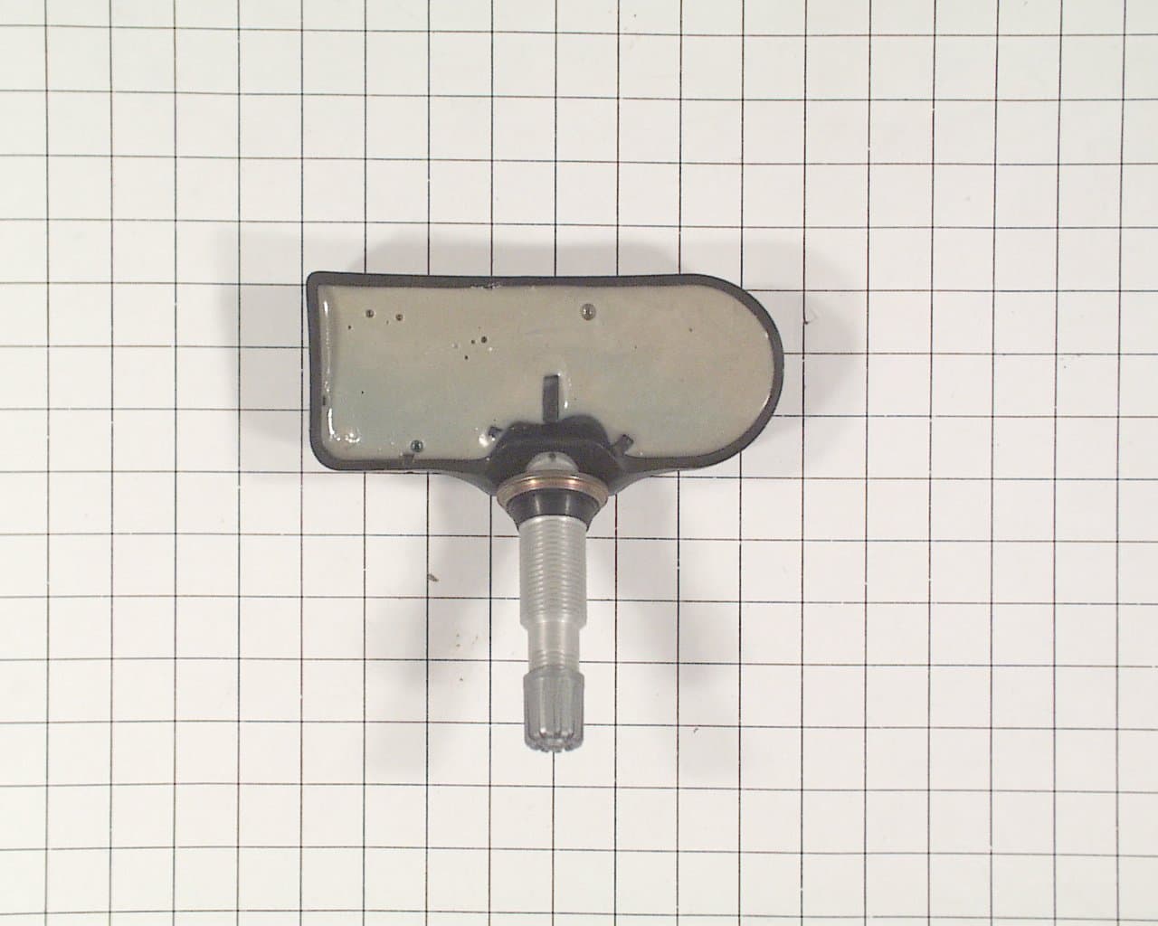
Click to zoom
Application Details
- Equipment Class
- DSC - Part 15 Security/Remote Control Transmitter
- Date of Grant
- Jul 29, 2003
- Application Purpose
- Original Equipment
- Date of Application
- Jul 03, 2003
- Equipment Note
- Tire Pressure Monitoring Transmitter
- Frequency Range
- 315.00000000 - 315.00000000
- Country
- Germany
Documents & Files
Document Text
Text extracted from the exhibit documents filed with the FCC. Open a document above to read the original.
Users Manual
SIEMENS VDO Automotive SV C BC P2 FCC ID:KR5S120123 IC:267T-S120123 File: Func_TG1B_USA.doc 1 of 6 User Manual / Functional Description of the Siemens VDO Tire Pressure Monitoring transmitter Generation 1B Type S120123 SIEMENS VDO Automotive SV C BC P2 FCC ID:KR5S120123 IC:267T-S120123 File: Func_TG1B_USA.doc 2 of 6 General description The tire pressure monitoring system (referred to as TireGuard) consists of the following units : - Tire guard transmitter type S120123 which includes an integrated pressure, temperature and acceleration sensor and a 315 MHz RF transmitter. - RF receiver unit which includes a 315 MHz receiver (not described in this document) The TireGuard system monitors a vehicle's tire pressure whilst driving or stationary. An electronic unit (wheel unit) inside each tire, mounted to the valve stem, periodically measures the actual tire pressure. By means of RF communication, this pressure information is transmitted to the RF receiver/decoder. When the vehicle starts moving, the TireGuard transmitter enters the driving mode. It measures and transmits RF burst 4 times per minute up to 30 bursts. The telegram length is approximately 30ms. After this period the transmitter measures and transmits data every minute. The transmitter will remain in driving mode for a period of 10 minutes after the vehicle is stopped. If, during any measurement period in driving mode, the pressure leakage is detected (difference compared to the last transmitted pressure value), a re- measure will occur after 5s taking in account the latest pressure value emitted as reference value. If the pressure continues changing, an additional transmission will be sent. For normal transmission the wheel must be rotating and the device must be pressurized. For factory testing, installation testing, ect., the device has been designed to be activated also by a 125kHz signal. For homologation testing one sample was modified for CW emission, that last about 2 min. after activation with LF. SIEMENS VDO Automotive SV C BC P2 FCC ID:KR5S120123 IC:267T-S120123 File: Func_TG1B_USA.doc 3 of 6 Technical description Carrier frequency: 315 MHz Frequency shift: ± 45 kHz Number of channels: 1 Duty cycle: < 0.1% Type of modulation: Frequency Shift Keying (FSK) Rated Output Power: < 10 mW Antenna: integral Voltage supply: 1 Lithium battery 3V (CR2450) Voltage supply range : 2.1 up to 3.2V SIEMENS VDO Automotive SV C BC P2 FCC ID:KR5S120123 IC:267T-S120123 File: Func_TG1B_USA.doc 4 of 6 Block diagram The block diagram below shows the main electronic units of the TireGuard transmitter: 3V LITHIUM BATTERY Learning coil RF CIRCUIT VALVE Pressure, temperature, acceleration sensor and μcontroller SIEMENS VDO Automotive SV C BC P2 FCC ID:KR5S120123 IC:267T-S120123 File: Func_TG1B_USA.doc 5 of 6 Label design Siemens VDO S120123 IC: 267T-S120123 FCC ID:KR5S120123 SIEMENS VDO Automotive SV C BC P2 FCC ID:KR5S120123 IC:267T-S120123 File: Func_TG1B_USA.doc 6 of 6 User manual information IC: 267T-S120123 FCC ID:KR5S120123 This device complies with part 15 of the FCC Rules and RSS-210. Operation is subject to the following two conditions: (1) This device may not cause harmful interference, and (2) this device must accept interference received, including interference that may cause undesired operation. NOTE Changes or modifications not expressly approved by the manufacturer could void the user ́s authority to operate the equipment.
Block Diagram
Annex No.7 Page 1 of 1 Block Diagram : TireGuard Type S 120 123 Oscillator frequencies generated or used in the device: Ceramic Resonator : 315 MHz
Cover Letter(s)
m. dudde hochfrequenz-technik Rottland 5a, D-51429 Bergisch-Gladbach DIN EN ISO/IEC 17025 zertifiziert Akkreditiertes Testhaus - Reg.-Nr.: TTI-P-G128/96 Tel. : +49 22 07 - 96 89 - 0 Fax : +49 22 07 - 96 89 - 20 email: [email protected] www.dudde.com Federal Communications Commission 7435 Oakland Mills Road Columbia, MD 21046 Gentlemen: This letter is to comply with Section 0.457(d)(2)(i) pertaining to confidential material. Siemens VDO Automotive AG, Siemensstraße 12, 93055 Regensburg / Germany would like the following documents regarding this submission for FCC ID: KR5S120123 to be kept confidential. 5WY 7243 TireGuard Type S120123 1. Page 10 of 10 Annex no. 8 document “Schematics” The above material contains trade secret or technical data, which would customarily be guarded from competitors. We do not want these documents to be accessible to the general public. Sincerely, m. dudde hochfrequenz-technik Ralf Trepper
External Photos
Annex No.1 Page 1 of 2 External Photographs of the Equipment Under Test TireGuard Type S120 123 EXTERNAL FRONT VIEW PHOTO Annex No.1 Page 2 of 2 EXTERNAL REAR VIEW PHOTO
ID Label/Location Info
Annex No.4 Page 1 of 2 FCC ID LABEL SAMPLE TireGuard Type S120 123 Annex No.4 Page 2 of 2 SKETCH OF FCC ID LABLE LOCATION
Internal Photos
Annex No.2 Page 1 of 2 Internal Photographs of the Equipment Under Test TireGuard Type S120 123 INTERNAL COMPONENT SIDE PHOTO Annex No.2 Page 2 of 2 INTERNAL SOLDER SIDE PHOTO
Operational Description
SIEMENS VDO AutomotiveSV C BC P2 FCC ID:KR5S120123IC:267T-S120123 File: Func_TG1B_USA.doc2 of 6 General description The tire pressure monitoring system (referred to as TireGuard) consists of the following units : - Tire guard transmitter type S120123 which includes an integrated pressure, temperature and acceleration sensor and a 315 MHz RF transmitter. - RF receiver unit which includes a 315 MHz receiver (not described in this document) The TireGuard system monitors a vehicle's tire pressure whilst driving or stationary. An electronic unit (wheel unit) inside each tire, mounted to the valve stem, periodically measures the actual tire pressure. By means of RF communication, this pressure information is transmitted to the RF receiver/decoder. When the vehicle starts moving, the TireGuard transmitter enters the driving mode. It measures and transmits RF burst 4 times per minute up to 30 bursts. The telegram length is approximately 30ms. After this period the transmitter measures and transmits data every minute. The transmitter will remain in driving mode for a period of 10 minutes after the vehicle is stopped. If, during any measurement period in driving mode, the pressure leakage is detected (difference compared to the last transmitted pressure value), a re- measure will occur after 5s taking in account the latest pressure value emitted as reference value. If the pressure continues changing, an additional transmission will be sent. For normal transmission the wheel must be rotating and the device must be pressurized. For factory testing, installation testing, ect., the device has been designed to be activated also by a 125kHz signal. For homologation testing one sample was modified for CW emission, that last about 2 min. after activation with LF.
Test Report
Annex No.3 Page 1 of 1 OCCUPIED BANDWITH PLOT TireGuard Type S120 123
Test Report
Page 1 of 21 m. dudde hochfrequenz-technik Rottland 5a Datum: 14.02.03 D-51429 Bergisch Gladbach Tel. +49 2207-9689-0 Fax +49 2207 9689-20 e-mail: [email protected] http://www.dudde.com TEST REPORT No.: 03001640 Date : 2003.06.25 EQUIPMENT UNDER TEST: Trade Name: Siemens VDO Model: 5WY7243 TireGuard Type S120 123 Serial No: none Prototype Equipment Category: Transmitter Manufacturer: Siemens VDO Automotive AG Address: Siemensstraße 12 D-93055 Regensburg Germany Phone: +49-941-790-3554 Fax: +49-941-790-133554 E-mail: [email protected] RELEVANT STANDARD: 47 CFR Part 15C - Intentional Radiators USED: ANSI C63.4-2002 TEST REPORT PREPARED BY: Ralf Trepper m.dudde hochfrequenz-technik Rottland 5a D-51429 Bergisch Gladbach Germany Phone: +49 2207 96890 Fax : +49 2207 968920 E-mail: [email protected] TEST PERSONNEL: SIGNATURE OF THE COMPANY OFFICIAL: Ralf Trepper Manfried Dudde FCC ID: KR5S120123 Test Report : 03001640 Page 2 of 21 Issue Date: 25.06.2003 EUT: 5WY7243 TireGuard Type S120 123 m. dudde hochfrequenz - technik Rottland 5a D-51429 Bergisch Gladbach Tel. +49 2207-96890 Fax +49 2207 968920 email [email protected] CONTENTS 1 GENERAL INFORMATION .................................................................................................................. 4 1.1 Purpose ................................................................................................................................................................... 4 1.2 Limits and Reservations .......................................................................................................................................... 4 1.3 Test Location ........................................................................................................................................................... 4 1.4 Manufacturer ........................................................................................................................................................... 4 1.5 Dates ....................................................................................................................................................................... 4 2 PRODUCT DESCRIPTION ................................................................................................................... 5 2.1 Equipment Under Test (EUT) ............................................................................................................................. 5 2.2 EUT Peripherals ...................................................................................................................................................... 5 2.4 Modifications Required for Compliance.............................................................................................................. 5 4 ANTENNA REQUIREMENT ..................................................................................................................... 7 4.1 Regulation ............................................................................................................................................................... 7 4.2 Result ...................................................................................................................................................................... 7 5 RADIATED EMISSIONS ............................................................................................................................ 8 5.1 Regulation ............................................................................................................................................................... 8 5.2 Test Equipment ....................................................................................................................................................... 9 5.3 Test Procedures ...................................................................................................................................................... 9 5.4 Calculation of Field Strength Limits....................................................................................................................... 10 5.5 Calculation of Average Correction Factor ............................................................................................................. 10 5.6 Field Strength Calculation ..................................................................................................................................... 10 5.7 Test Results...................................................................................................................................................... 11 5.7.1 Model 5WY7243TireGuard Type S120 123............................................................................................... 11 6 CONDUCTED EMISSIONS TESTS ........................................................................................................ 13 6.1 Regulation ............................................................................................................................................................. 13 6.2 Test Equipment ..................................................................................................................................................... 13 6.3 Test Procedures .................................................................................................................................................... 13 6.4 Test Results........................................................................................................................................................... 13 7 PERIODIC OPERATION CHARACTERISTICS.................................................................................. 14 7.1 Periodic Operation................................................................................................................................................. 14 7.1.1 Regulation.........................................................................…
Text truncated - open the document above for the full version.
Test Setup Photos
Annex No.6 Page 1 of 1 Test Setup Photos : TireGuard Type S120 123
Contact Information
Applicant
Thomas Heselberger
Test Firm
m. dudde hochfrequenz-technikManfred Dudde
Technical Specifications
| # | Rule Parts | Frequency Range | Power Output |
|---|---|---|---|
| 1 | 15.231(e) | 315 MHz - 315 MHz | - |
Other Applications from Continental Automotive Technologies GmbH
KR5FERKEY25
Jul 06, 2026Romete Car Key
Equipment Class
DSC - Part 15 Security/Remote Control TransmitterKR5KAM01
May 12, 2026KAM (Key Authentication Module)
Equipment Class
DCD - Part 15 Low Power Transmitter Below 1705 kHzKR5HFM501
Apr 29, 2026Hand Free Module
Equipment Class
DCD - Part 15 Low Power Transmitter Below 1705 kHzKR5TXPZ6
Mar 05, 2026Radio Frequency Transmitter
Equipment Class
DSC - Part 15 Security/Remote Control TransmitterKR5TXPZ5
Mar 05, 2026TXPZ5
Equipment Class
DSC - Part 15 Security/Remote Control Transmitter