KR5VWFS14TRemote Keyless Entry
Continental Automotive Technologies GmbH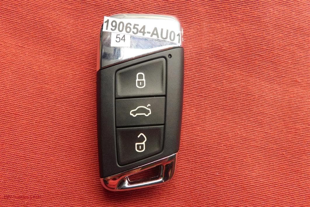
Click to zoom
Application Details
- Equipment Class
- DSC - Part 15 Security/Remote Control Transmitter
- Date of Grant
- Mar 26, 2020
- Application Purpose
- Original Equipment
- Date of Application
- Mar 26, 2020
- Equipment Note
- Remote Keyless Entry
- Frequency Range
- 434.40000000 - 434.40000000
- Country
- Germany
Documents & Files
Document Text
Text extracted from the exhibit documents filed with the FCC. Open a document above to read the original.
Users Manual
Continental 1 of 2 Owner manual Radio frequency transmitter Type FS14T FS14TK Continental 2 of 2 General: The FS14 is a transmitter designed to provide remote keyless entry, passive entry, passive engine start, and immobilization functionality. Within the housing is applied an inner container, containing a lower container and container cover which are laser welded. Within the container is placed a PCB, which is the same type for all variants and containing a different number of switches. Owner Manual Information: USA: FCC ID:KR5VWFS14TK This device complies with Part 15 of the FCC Rules. Operation is subject to the following two conditions: (1) this device may not cause harmful interference, and (2) this device must accept any interference received, including interference that may cause undesired operation. Changes or modifications not expressly approved by the party responsible for compliance could void the user's authority to operate the equipment.
Attestation Statements
Continental Automotive GmbH Siemensstraße 12 93055 Regensburg Germany 2020-03-10 To whom it may concern, Hereby we declare that FS14T and FS14TK are electrically identical. The only difference is the housing of the device: Sincerely, Signature Name Dagmar Kolar Job Title Type approval manager Company Continental Automotive GmbH
Attestation Statements
@ntÍnentals LABEL LOCATION LETTER 2020-02-0s FCC ID:KRSVWFSl4T To whom it may concern, Please be advised that the FCC ID is placed on ihe inside of the product, under the cover. The FCC ID is therefore not visible when the product is in use, however the product will be supplied with the cover removed to ensure that the FCC ID is visible at the pãint of ,ule. The FCC ID is also in the user manual. Sincerely, Dagmar Kolar Type approval manager Continental Automotíve GmbH
Cover Letter(s)
@ntinentals LerrrR or Acerucv 2020-oI-2I Element Materials Tech nology 100 Frobisher Business park Malvern Worcestershire WR14 1BX UK To Whom It May Concern: We certify that we are not subject to denial of federal benefits, that includes FCC benefits, pursuant to Section 5301 of the Anti-Drug Abuse ACT of 1gBB, U.S.C, 862. Further, no PartY, as defined in 47 CFR 1.2002(b), to the application, is subject to denial of federal benefits, that includes FCC benefits, Thank you for your attention to this matter Yours faithfully Company: Continental Automotive GmbH Siemenstrasse 12 93055 Regensburg, Germany Signature Full Name Dagmar Kolar
Cover Letter(s)
Sample Request for Confidentiality Letter-FCC Date: 2020-01-19 Federal Communications Commission Authorization and Evaluation Division 7435 Oakland Mills Road Columbia, Maryland 21046 Re: Request for confidentiality FCC ID: KR5VWFS14T To whom it may concern, We hereby respectfully request that under the provision of 47 CFR 0.459 and 0.457(d) the documents listed below and attached with this application for certification be provided with confidential status. Schematics.pdf Operational Description.pdf Frequency Block Diagrams.pdf Any exhibit / information for which we have requested confidentiality, but which may not be accorded such treatment by the FCC, should be returned to us. The documents listed above contain trade secrets that are treated as confidential by us. Substantial competitive harm to us could result should they be made available to the public. Sincerely, Name: Christian Kiermeier Job Title
External Photos
EMV TESTHAUS GmbH Gustav-Hertz-Straße 35 94315 Straubing Germany Continental Automotive GmbH RF Transmitter FS14T 190654-AU01+W01 Annex B Page 1 of 5 1 Annex B – EUT pictures 1.1 List of Pictures Picture 1: FS14T, version FS14T with test mode - top side ............................................... 2 Picture 2: FS14T, version FS14T with test mode - bottom side ......................................... 2 Picture 3: FS14T, version FS14T with test mode - top side ............................................... 3 Picture 4: FS14T, version FS14T with test mode - bottom side ......................................... 3 Picture 5: FS14T, version FS14TK with test mode - top side ............................................ 4 Picture 6: FS14T, version FS14TK with test mode - bottom side ...................................... 4 Picture 7: FS14T, version FS14TK with application mode - top side ................................. 5 Picture 8: FS14T, version FS14TK with application mode - bottom side ......................... 5 EMV TESTHAUS GmbH Gustav-Hertz-Straße 35 94315 Straubing Germany Continental Automotive GmbH RF Transmitter FS14T 190654-AU01+W01 Annex B Page 2 of 5 Picture 1: FS14T, version FS14T with test mode - top side Picture 2: FS14T, version FS14T with test mode - bottom side EMV TESTHAUS GmbH Gustav-Hertz-Straße 35 94315 Straubing Germany Continental Automotive GmbH RF Transmitter FS14T 190654-AU01+W01 Annex B Page 3 of 5 Picture 3: FS14T, version FS14T with test mode - top side Picture 4: FS14T, version FS14T with test mode - bottom side EMV TESTHAUS GmbH Gustav-Hertz-Straße 35 94315 Straubing Germany Continental Automotive GmbH RF Transmitter FS14T 190654-AU01+W01 Annex B Page 4 of 5 Picture 5: FS14T, version FS14TK with test mode - top side Picture 6: FS14T, version FS14TK with test mode - bottom side EMV TESTHAUS GmbH Gustav-Hertz-Straße 35 94315 Straubing Germany Continental Automotive GmbH RF Transmitter FS14T 190654-AU01+W01 Annex B Page 5 of 5 Picture 7: FS14T, version FS14TK with application mode - top side Picture 8: FS14T, version FS14TK with application mode - bottom side
ID Label/Location Info
LABEL DRAFT – USA - Continental KEYFOB Continental FS14T, FS14TK (434 MHz) Continental FS14T FCC ID:KR5VWFS14T Continental FS14TK FCC ID:KR5VWFS14T
Internal Photos
EMV TESTHAUS GmbH Gustav-Hertz-Straße 35 94315 Straubing Germany Continental Automotive GmbH RF Transmitter FS14T 190654-AU01+W01 Annex C Page 1 of 5 1 Annex C – documentation 1.1 List of Pictures Picture 1: Opened FS14T, version FS14T with battery (top view) ..................................... 2 Picture 2: Opened FS14T, version FS14T without battery (top view) ................................ 2 Picture 3: Opened FS14T, version FS14TK with battery (rear view) ................................. 3 Picture 4: Opened FS14T, version FS14TK without battery (top view) .............................. 3 Picture 5: Used battery (top view) ...................................................................................... 4 Picture 6: EUT module (top view) ...................................................................................... 4 Picture 7: EUT module (back view) ................................................................................... 5 EMV TESTHAUS GmbH Gustav-Hertz-Straße 35 94315 Straubing Germany Continental Automotive GmbH RF Transmitter FS14T 190654-AU01+W01 Annex C Page 2 of 5 Picture 1: Opened FS14T, version FS14T with battery (top view) Picture 2: Opened FS14T, version FS14T without battery (top view) EMV TESTHAUS GmbH Gustav-Hertz-Straße 35 94315 Straubing Germany Continental Automotive GmbH RF Transmitter FS14T 190654-AU01+W01 Annex C Page 3 of 5 Picture 3: Opened FS14T, version FS14TK with battery (rear view) Picture 4: Opened FS14T, version FS14TK without battery (top view) EMV TESTHAUS GmbH Gustav-Hertz-Straße 35 94315 Straubing Germany Continental Automotive GmbH RF Transmitter FS14T 190654-AU01+W01 Annex C Page 4 of 5 Picture 5: Used battery (top view) Picture 6: EUT module (top view) EMV TESTHAUS GmbH Gustav-Hertz-Straße 35 94315 Straubing Germany Continental Automotive GmbH RF Transmitter FS14T 190654-AU01+W01 Annex C Page 5 of 5 Picture 7: EUT module (back view)
Test Report
All test results apply to the tested sample only. Multiplication and publication is prohibited unless written consent has been provided beforehand by the EMV TESTHAUS GmbH RF test report 190654-AU01+W01_R2 Continental Automotive GmbH RF Transmitter FS14T Customer: Continental Automotive GmbH Siemensstraße 12 93055 Regensburg Germany Tel.: +49 941 790-6699-0 EMV TESTHAUS GmbH Gustav-Hertz-Straße 35 94315 Straubing Germany Continental Automotive GmbH RF transmitter FS14T 190654-AU01+W01_R2 Page 2 of 37 EMV TESTHAUS GmbH Gustav-Hertz-Straße 35 94315 Straubing Germany Tel.: +49 9421 56868-0 Fax: +49 9421 56868-100 Email: [email protected] Accreditation: FCC test firm accreditation expiration date: 2021-05-30 MRA US-EU, FCC designation number: DE0010 BnetzA-CAB-02/21-02/5 Valid until 2023-11-26 Recognized on March 14 th , 2019 by the Department of Innovation, Science and Economic Development (ISED) Canada as a wireless testing laboratory CAB identifier: DE0011 Location of Testing: EMV TESTHAUS GmbH Gustav-Hertz-Straße 35 94315 Straubing Germany The technical accuracy is guaranteed through the quality management of EMV TESTHAUS GmbH. EMV TESTHAUS GmbH Gustav-Hertz-Straße 35 94315 Straubing Germany Continental Automotive GmbH RF transmitter FS14T 190654-AU01+W01_R2 Page 3 of 37 Table of contents 1 Summary of test results ............................................................................................................ 6 2 Referenced publications ........................................................................................................... 7 3 Equipment under test (EUT) ..................................................................................................... 8 4 Test configuration and mode of operation ................................................................................. 9 4.1 Test configuration .............................................................................................................. 9 4.2 Mode of operation .............................................................................................................. 9 5 Measurement Procedures ...................................................................................................... 10 5.1 20 dB bandwidth .............................................................................................................. 10 5.2 Occupied bandwidth (99%) .............................................................................................. 10 5.3 Spurious radiated emissions 9 kHz to 10 th harmonic ........................................................ 11 5.4 Radiated emissions ......................................................................................................... 11 6 Test results ............................................................................................................................. 15 6.1 Field strength of fundamental wave ................................................................................. 16 6.2 Spurious radiated emissions 9 kHz to 10th harmonic ....................................................... 18 6.3 Correction for pulse operation (duty cycle) ....................................................................... 27 6.4 20 dB bandwidth .............................................................................................................. 31 6.5 Signal deactivation........................................................................................................... 33 7 Equipment calibration status ................................................................................................... 35 8 Measurement uncertainties .................................................................................................... 36 9 Revision history ...................................................................................................................... 37 10 Additional documents ............................................................................................................. 37 EMV TESTHAUS GmbH Gustav-Hertz-Straße 35 94315 Straubing Germany Continental Automotive GmbH RF transmitter FS14T 190654-AU01+W01_R2 Page 4 of 37 List of figures Figure 1: Setup for radiated emission test below 30 MHz .............................................................. 11 Figure 2: Setup for radiated emission test from 30 MHz to 1 GHz ................................................. 12 Figure 3: Setup for radiated emission test above 1 GHz ................................................................ 13 Figure 4: Chart of spurious radiated emission test 9 kHz - 30 MHz of FS14T, version FS14T, in position X and antenna parallel ..................................................................................................... 20 Figure 5: Chart of spurious radiated emission test 9 kHz - 30 MHz of FS14T, version FS14TK, in position Z and antenna in line ........................................................................................................ 21 Figure 6: Chart of spurious radiated emission test 30 MHz - 1 GHz of FS14T, version FS14T in position Y ...................................................................................................................................... 22 Figure 7: Chart of spurious radiated emission test 30 MHz - 1 GHz of FS14T, version FS14TK in position Z....................................................................................................................................... 23 Figure 8: Chart of spurious radiated emission final test 1 GHz to 10 th harmonic of FS14T, version FS14T in position X ....................................................................................................................... 25 Figure 9: Chart of spurious radiated emission final test 1 GHz to 10 th harmonic of FS14T, version FS14TK in position Z .........................................................................................…
Text truncated - open the document above for the full version.
Test Setup Photos
EMV TESTHAUS GmbH Gustav-Hertz-Straße 35 94315 Straubing Germany Continental Automotive GmbH RF Transmitter FS14T 190654-AU01+W01 Annex A Page 1 of 11 1 Annex A – Test setup 1.1 List of Pictures Picture 1: CDC, test setup radiated emission test 9 kHz -30 MHz of FS14T, version FS14T (front view) ............................................................................................................. 2 Picture 2: CDC, test setup radiated emission test 9 kHz -30 MHz of FS14T, version FS14T (back view) ............................................................................................................. 2 Picture 3: CDC, test setup radiated emission test 9 kHz -30 MHz of FS14T, version FS14TK (front view) ........................................................................................................... 3 Picture 4: CDC, test setup radiated emission test 9 kHz -30 MHz of FS14T, version FS14TK (back view) .......................................................................................................... 3 Picture 5: SAC, radiated emission test 30 MHz -1 GHz of FS14T, version FS14T (front view) .................................................................................................................................. 4 Picture 6: SAC, radiated emission test 30 MHz -1 GHz of FS14T, version FS14T (rear view) .................................................................................................................................. 4 Picture 7: SAC, radiated emission test 30 MHz -1 GHz of FS14T, version FS14TK (front view) .................................................................................................................................. 5 Picture 8: SAC, radiated emission test 30 MHz -1 GHz of FS14T, version FS14TK (rear view) .................................................................................................................................. 5 Picture 9: AC, radiated emission 1 GHz – 5 GHz of FS14T, version FS14T (front view) ... 6 Picture 10: AC, radiated emission 1 GHz – 5 GHz of FS14T, version FS14T (rear view) . 6 Picture 11: AC, radiated emission 1 GHz – 5 GHz of FS14T, version FS14TK (front view) .................................................................................................................................. 7 Picture 12: AC, radiated emission 1 GHz – 5 GHz of FS14T, version FS14TK (rear view) .................................................................................................................................. 7 Picture 13: EUT-position X ................................................................................................ 8 Picture 14: EUT-position Y ................................................................................................ 8 Picture 15: EUT-position Z................................................................................................. 9 Picture 16: Relative measurements of duty cycle, occupied bandwidth and 20 dB bandwidth .......................................................................................................................... 9 Picture 17: Relative measurement of signal deactivation .................................................. 10 Picture 18: EUT used for signal deactivation (top view) .................................................... 10 Picture 19: EUT used for signal deactivation (detailed view) ............................................. 11 Picture 20: EUT used for signal deactivation (rear view) ................................................... 11 EMV TESTHAUS GmbH Gustav-Hertz-Straße 35 94315 Straubing Germany Continental Automotive GmbH RF Transmitter FS14T 190654-AU01+W01 Annex A Page 2 of 11 Picture 1: CDC, test setup radiated emission test 9 kHz -30 MHz of FS14T, version FS14T (front view) Picture 2: CDC, test setup radiated emission test 9 kHz -30 MHz of FS14T, version FS14T (back view) EMV TESTHAUS GmbH Gustav-Hertz-Straße 35 94315 Straubing Germany Continental Automotive GmbH RF Transmitter FS14T 190654-AU01+W01 Annex A Page 3 of 11 Picture 3: CDC, test setup radiated emission test 9 kHz -30 MHz of FS14T, version FS14TK (front view) Picture 4: CDC, test setup radiated emission test 9 kHz -30 MHz of FS14T, version FS14TK (back view) EMV TESTHAUS GmbH Gustav-Hertz-Straße 35 94315 Straubing Germany Continental Automotive GmbH RF Transmitter FS14T 190654-AU01+W01 Annex A Page 4 of 11 Picture 5: SAC, radiated emission test 30 MHz -1 GHz of FS14T, version FS14T (front view) Picture 6: SAC, radiated emission test 30 MHz -1 GHz of FS14T, version FS14T (rear view) EMV TESTHAUS GmbH Gustav-Hertz-Straße 35 94315 Straubing Germany Continental Automotive GmbH RF Transmitter FS14T 190654-AU01+W01 Annex A Page 5 of 11 Picture 7: SAC, radiated emission test 30 MHz -1 GHz of FS14T, version FS14TK (front view) Picture 8: SAC, radiated emission test 30 MHz -1 GHz of FS14T, version FS14TK (rear view) EMV TESTHAUS GmbH Gustav-Hertz-Straße 35 94315 Straubing Germany Continental Automotive GmbH RF Transmitter FS14T 190654-AU01+W01 Annex A Page 6 of 11 Picture 9: AC, radiated emission 1 GHz – 5 GHz of FS14T, version FS14T (front view) Picture 10: AC, radiated emission 1 GHz – 5 GHz of FS14T, version FS14T (rear view) EMV TESTHAUS GmbH Gustav-Hertz-Straße 35 94315 Straubing Germany Continental Automotive GmbH RF Transmitter FS14T 190654-AU01+W01 Annex A Page 7 of 11 Picture 11: AC, radiated emission 1 GHz – 5 GHz of FS14T, version FS14TK (front view) Picture 12: AC, radiated emission 1 GHz – 5 GHz of FS14T, version FS14TK (rear view) EMV TESTHAUS GmbH Gustav-Hertz-Straße 35 94315 Straubing Germany Continental Automotive GmbH RF Transmitter FS14T 190654-AU01+W01 Annex A Page 8 of 11 Picture 13: EUT-position X Picture 14: EUT-position Y EMV TESTHAUS GmbH Gustav-Hertz-Straße 35 94315 Straubing Germany Continental Automotive GmbH RF Transmitter FS14T 190654-AU01+W01 Annex A Page 9 of 11 Picture 15: EUT-position Z Picture 16: Relative mea…
Text truncated - open the document above for the full version.
Contact Information
Applicant
Thomas Heselberger
Test Firm
Element Materials Technology Straubing GmbHChristian Kiermeier
Technical Specifications
| # | Rule Parts | Frequency Range | Power Output |
|---|---|---|---|
| 1 | 15.231 | 434.4 MHz - 434.4 MHz | - |
Other Applications from Continental Automotive Technologies GmbH
KR5FERKEY25
Jul 06, 2026Romete Car Key
Equipment Class
DSC - Part 15 Security/Remote Control TransmitterKR5KAM01
May 12, 2026KAM (Key Authentication Module)
Equipment Class
DCD - Part 15 Low Power Transmitter Below 1705 kHzKR5HFM501
Apr 29, 2026Hand Free Module
Equipment Class
DCD - Part 15 Low Power Transmitter Below 1705 kHzKR5TXPZ6
Mar 05, 2026Radio Frequency Transmitter
Equipment Class
DSC - Part 15 Security/Remote Control TransmitterKR5TXPZ5
Mar 05, 2026TXPZ5
Equipment Class
DSC - Part 15 Security/Remote Control Transmitter