L7B-STAR16-1EZ-Star CDMA-1XRTT
Global Data Inc.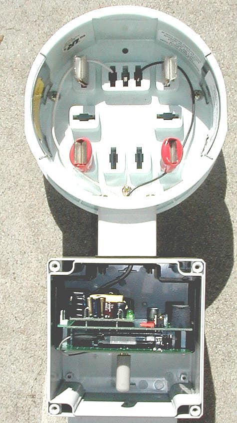
Click to zoom
Application Details
- Equipment Class
- PCB - PCS Licensed Transmitter
- Date of Grant
- Dec 14, 2003
- Application Purpose
- Original Equipment
- Date of Application
- Nov 03, 2003
- Equipment Note
- EZ-Star CDMA-1XRTT
- Frequency Range
- 1851.25000000 - 1908.75000000
- Company
- Global Data Inc.
- Country
- United States
Documents & Files
Document Text
Text extracted from the exhibit documents filed with the FCC. Open a document above to read the original.
Users Manual
EZEZ--StarStar CDMA/1XRTT Cellular AMR Interface Technical Reference Manual Quality Communications Products 11-1030-02 Table of Contents 1 INTRODUCTION 1 1.1 OVERVIEW 1 1.2 NETWORK MODES 1 1.3 FEATURES 1 2 THEORY OF OPERATION 1 3 ARCHITECTURE 2 3.1 SERIAL INTERFACE 2 3.2 MICRO CONTROLLER 2 3.3 RADIO 2 4 MODULE INTERFACE AND CONNECTORS 3 4.1 POWER SUPPLY LED 4 4.2 SIGNAL QUALITY LED 4 4.3 INTERNAL ANTENNA AND SMA CONNECTOR 4 4.4 RS-232 RJ-11 JACK 4 5 CONFIGURATION AND OPERATION 5 5.1 ESTABLISHING CELLULAR SERVICE 5 5.2 ACTIVATING EZ-STAR 5 5.3 EVALUATING SERVICE QUALITY 6 6 SOFTWARE INTERFACE 6 6.1 AT COMMAND OVERVIEW 6 6.1.1 COMMAND FORMAT 6 6.1.2 ESCAPE CODE SEQUENCE 6 6.2 AT COMMAND SET 7 6.2.1 GENERIC CONTROL COMMANDS 7 6.2.2 DTE INTERFACE COMMANDS 9 6.2.3 CALL PROGRESS COMMANDS 10 6.2.4 CELLULAR CONTROL COMMANDS 11 6.2.5 REMOTE CONFIGURATION COMMAND 12 6.3 S-REGISTERS 13 6.3.1 S-REGISTER SUMMARY 13 7 SPECIFICATIONS 14 7.1 FCC NOTICES 14 7.2 ELECTRICAL AND ENVIRONMENTAL 14 1 1 INTRODUCTION 1.1 OVERVIEW The EZ-Star CDMA/1XRTT cellular AMR interface is an end-point communications interface device designed specifically for automated meter reading applications. EZ-Star is based on a combination of Global Data’s standard StarPoint communications platform and the Marwell family of meter socket adapters. The resulting product provides an economical AMR solution that rivals under the glass solutions for cost of installation and surpasses under the glass solutions for ease of maintenance and ease of upgrade. Designed to operate on networks utilizing the CDMA and/or 1XRTT Packet Radio Service, EZ-Star supports bi-directional data communication which may be originated by either the meter or host application. 1.2 NETWORK MODES The CDMA network is designed to support digital voice and data transmission. Data transmission can occur as either circuit switched data, or with the 1XRTT overlay, as packet data. Many traditional host applications communicate via modem to endpoints through analog cellular connections or public switched telephone networks (PSTN). Utilizing the CDMA circuit switched data mode, these applications can seamlessly switch to digital cellular connectivity. Host applications capable of communicating via Internet Protocol (IP) can utilize 1XRTT as a means of communicating with endpoint hardware. In 1XRTT mode, data remains in IP packet format from the host application through the carrier network, to the endpoint communication device, and back. 1.3 FEATURES • Dual Frequency Bands – 800Mhz (Cellular) and 1900Mhz (PCS) • Wide range AC power supply • Multiple data modes - Circuit Switched data and 1XRTT packet data • Thermal Protection • AMR Meter Direct Connection – RJ-11 jack accepts the standard RS-232 option board cable provided with General Electric, Elseter (ABB) and Landis + Gyr (Siemens) meters. • Remote Reprogramming – A smart-change feature allows for remote reprogramming of the device parameters without dispatching personnel to the remote location. 2 THEORY OF OPERATION The CDMA/1XRTT networks support two methods of data transmission: circuit switched and packet switched. In circuit switch mode, CDMA provides an error corrected data path through the network. Because of the error correction characteristics, applications must be prepared for lower throughput and higher latency characteristics that are similar to those experienced on a packet network. In circuit switched mode, modem banks in the CDMA network act as the gateway for all inbound and outbound data traffic. These modems communicate with the customer’s host-application modem and deliver a digital data stream into the CDMA network where it is then delivered to the endpoint device via an 2 error correcting protocol. In 1XRTT packet based communications, the customer’s host application communicates with the CDMA network via an IP connection. The 1XRTT network delivers packet data directly to an endpoint device such as EZ-Star. The EZ-Star contains TCP/IP protocol support so that standard asynchronous meters may be attached to the 1XRTT network. Various protocol layers within the EZ- Star may be disabled to accommodate meters that are IP capable. 3 ARCHITECTURE The EZ-Star integrates multiple components into a compact rugged design. These components work together to provide CDMA/1XRTT communications optimized for AMR applications. The components include an RS-232 serial interface, a micro controller with onboard memory, and a CDMA/1XRTT radio. 3.1 SERIAL INTERFACE The RS-232 serial interface may be configured for direct connection to most electric meters by setting jumpers on the EZ-Star circuit board. A quick connect RJ-11 is provided for connections to electric meters manufactured by General Electric, Elster, and Landis + Gyr. 3.2 MICRO CONTROLLER The Micro Controller provides a standard feature set including configuration control, diagnostic tools and protocol support. Global Data firmware is designed to optimize network efficiency by controlling packet size, framing and latency. On board user expandable flash memory provides support for customized protocols. Standard memory included onboard the Micro Controller is 128Kb with over 115Kb available for customer customized protocol development. The device may be ordered with an optional 256Kb of flash memory in place of the standard 128Kb. 3.3 RADIO The CDMA/1XRTT Radio included in EZ-Star has been designed specifically for telemetry applications. This device has been tightly integrated with the Micro Controller and Serial Interface to provide dependable cellular service with standard interfaces. 3 4 MODULE INTERFACE AND CONNECTORS POWER SUPPLY, POWER “ON” LED SIGNAL QUALITY LED (SEE FIGURE 3 FOR DETAILS) FIGURE 1 INTERNAL ANTENNA SMA FEMALE CONNECTOR FOR EXTERNAL ANTENNA RS-232 RJ-11 JACK RS 232 CONFIGURATION JUMPERS (SEE FIG. 2 FOR DETAIL) FIGURE 2 LANDIS + GYR AND ELSTER JUMPER CONFIGURATION GE / KV2 JUMPER CONFIGURATION RS-232 JUMPER CONFIGURATION View from bottom of…
Text truncated - open the document above for the full version.
Attestation Statements
A Global Data Company 2250 Obispo Ave., Suite 105 •• Signal Hill, California 90755 •• (562) 597-3908 •• fax (562) 597-8572 www.globaldata.com Federal Communications Commission 7435 Oakland Mills Road Columbia, MD 21046 Friday, March 28, 2003 Gentlemen: This is your letter of authorization to accept our appointment of Elliott Laboratories, Inc. as Agent for Global Data Inc, at 2250 Obispo Ave. Sutie 105 Signal Hill, California 90755, to sign applications before the Commission and to make representations to you on our behalf. Elliott Laboratories is to receive and exchange data between our company and the Commission. This authorization is made pursuant to Section 2.911(c) of the FCC Rules and expires on July 31 st 2003. I hereby certify on behalf of Global Data Inc, at 2250 Obispo Ave. Sutie 105 Signal Hill, California 90755, ("Applicant") that neither Applicant nor any party to the application (officers, directors, and 5% shareholders) is subject to a denial of Federal benefits that includes FCC benefits pursuant to section 5301 of the Anti-Drug Abuse Act of 1988. 21 U.S.C. 853a. Sincerely, Ken Chang Director, Hardware Engineering
External Photos
EZ-STAR CDMA/1XRTT with 1.9GHz antenna EZ-STAR CDMA/1XRTT with 800MHz antenna
Internal Photos
Anydata DT2000-Dual Radio – Top Side Anydata DT2000-Dual Radio – Bottom Side
RF Exposure Info
MPE Calculations FCC part 1.1310, Table 1 limits the power density for uncontrolled exposure to 1mW/ cm 2 for systems operating in FCC Part 22H and 24E. The distance, d(cm) from the antenna at which the power density, P d (mW/cm 2 ) is below this limit is calculated from the maximum EIRP, P t (mW) using the equation: P d = P t /(4 πd 2 ) Re-arranging for the distance at which the power density is 1mW/cm2 gives: d = √ (P t /(4 π)) Frequency Maximum Output Power (dBm) EIRP (mW) Pd at 20cm Calculated distance (in cm) where Pd < 1mW/ cm2 824-849 MHz 18 63.1 0.01255 2.24 1850 – 1910 MHz 25.8 380.2 0.0756 5.50 The minimum distance from the antenna that the power density is 1mW/ cm 2 and the calculated minimum distance is 2.24 cm (22H&RSS-129) and 5.5 cm (24E&RSS-133). This information is detailed in the user manual as follow: To satisfy FCC RF exposure compliance requirements for a mobile transmitting device, this device and its antenna should generally maintain a separation distance of 20cm or more from a person’s body.
Test Report
2.1033(c)(14)/2.1055/22.355/24.235- FREQUENCY STABILITY Customer: Anydata Date: 16-Apr-02 WO#: 78691 Test Engineer: Dustin Oaks Part 22.355: 800 MHz Band Frequency: 836.52 MHz Temperature DC Voltage Frequency (MHz) Deviation (MHz) Limit (MHz) -30 12 836.52102 0.00102 .0020913 -20 12 836.52100 0.00100 .0020913 -10 12 836.52090 0.00090 .0020913 0 12 836.52095 0.00095 .0020913 10 12 836.52096 0.00096 .0020913 20 10.2 836.52032 0.00032 .0020913 20 12 836.52030 0.00030 .0020913 20 13.8 836.52045 0.00045 .0020913 30 12 836.52070 0.00070 .0020913 40 12 836.52021 0.00021 .0020913 50 12 836.51991 0.00009 .0020913 RSS-129 (9.2.2): 800MHz Band Frequency: 836.52 MHz Temperature Vs. Power Reference Power = 23.9 dBm Temperature Deviation Power (Celsius) (dB) (dBm) -30 0.40 23.5 -20 0.20 23.7 -10 0.70 23.2 0 0.80 23.1 10 0.40 23.5 20 0.40 23.5 30 0.30 23.6 40 0.20 23.7 50 0.10 23.8 60 0.00 23.9 Frequency: 836.52 MHz Voltage Vs. Power Reference Power = 23.9 dBm Nominal Voltage is 12Vdc. Voltage Voltage Deviation Power (Dc) (DC) (dB) (dBm) 85% 10.2 0.10 23.8 115% 13.8 0.20 23.7 Part 24.235: 1900 MHz Band Frequency: 1851.25 MHz Temperature DC Voltage Frequency (MHz) Deviation (MHz) Limit (MHz) -30 12 1851.21 0.04 Stays within the authorized Band -20 12 1851.25 0 Stays within the authorized Band -10 12 1851.27 0.02 Stays within the authorized Band 0 12 1851.26 0.01 Stays within the authorized Band 10 12 1851.28 0.03 Stays within the authorized Band 20 10.2 1851.24 0.01 Stays within the authorized Band 20 12 1851.25 0 Stays within the authorized Band 20 13.8 1851.30 0.05 Stays within the authorized Band 30 12 1851.22 0.03 Stays within the authorized Band 40 12 1851.22 0.03 Stays within the authorized Band 50 12 1851.23 0.02 Stays within the authorized Band Frequency: 1980.75 MHz Temperature DC Voltage Frequency (MHz) Deviation (MHz) Limit (MHz) -30 12 1908.79 0.04 Stays within the authorized Band -20 12 1908.73 0.02 Stays within the authorized Band -10 12 1908.74 0.01 Stays within the authorized Band 0 12 1908.79 0.04 Stays within the authorized Band 10 12 1908.76 0.01 Stays within the authorized Band 20 10.2 1908.77 0.02 Stays within the authorized Band 20 12 1908.74 0.01 Stays within the authorized Band 20 13.8 1908.73 0.02 Stays within the authorized Band 30 12 1908.76 0.01 Stays within the authorized Band 40 12 1908.77 0.02 Stays within the authorized Band 50 12 1908.72 0.03 Stays within the authorized Band
Test Report
September 18, 2003 Chief, Equipment Authorization Branch, Authorization and Evaluation Division, Office of Engineering and Technology FEDERAL COMMUNICATIONS COMMISSION P.O. Box 358315 Pittsburgh, PA 15251-5315 Gentlemen: The enclosed documents constitute a formal submittal and request for a Certification pursuant to Part 24E of FCC Rules (CFR 47) regarding the Personal Communication Service devices. Certification is being requested for Global Data model EZ-Star CDMA-1XRTT Cellular AMR Meter Interface. The EZ-Star CDMA-1XRTT Cellular AMR Meter Interface has been tested and found to comply with FCC Part 24E limits for intentional radiators Elliott Laboratories, as duly authorized agent prepared this submittal. A copy of the letter of our appointment as agent is enclosed. If there are any questions or if further information is needed, please contact Elliott Laboratories for assistance. Sincerely, Juan Martinez Sr. EMC Engineer JMM/dmg Enclosures: Agent Authorization Letter Confidentiality Letter Schematics External and Internal Photos Manual Theory of Operations FCC ID Label and Location Emissions Test Report with Exhibits File: R50357 Page 1 of 16 Electromagnetic Emissions Test Report In Accordance With Industry Canada Radio Standards Specification 133 issue 2, FCC Part 24 Subpart E on the Global Data Model: EZ-Star CDMA-1XRTT Cellular AMR Meter Interface FCC ID NUMBER: L7B-STAR16-1 UPN: 2064-STAR16-1 APPLICANT: Global Data 2250 Obispo Ave Suite 105 Signal Hill, CA 90806 TEST SITE: Elliott Laboratories, Inc. 684 W. Maude Ave Sunnyvale, CA 94086 REPORT DATE: September 18, 2003 FINAL TEST DATE: August 27, 2003 AUTHORIZED SIGNATORY: ______________________________ Sr. EMC Engineer This report shall not be reproduced, except in its entirety, without the written approval of Elliott Laboratories, Inc. Elliott Laboratories, Inc. -- EMC Department Test Report Report Date: September 18, 2003 File: R50357 Page 2 of 16 Pages TABLE OF CONTENTS COVER PAGE..................................................................................................................................................................................1 TABLE OF CONTENTS...............................................................................................................................................................2 FCC CERTIFICATION INFORMATION..................................................................................................................................3 DECLARATIONS OF COMPLIANCE......................................................................................................................................5 SCOPE.............................................................................................................................................................................................6 OBJECTIVE...................................................................................................................................................................................6 SUMMARY OF TEST RESULTS................................................................................................................................................7 PART 24E AND RSS-133 TEST SUMMARY........................................................................................................................7 MEASUREMENT UNCERTAINTIES.........................................................................................................................................8 EQUIPMENT UNDER TEST (EUT) DETAILS..........................................................................................................................9 GENERAL...................................................................................................................................................................................9 ENCLOSURE..............................................................................................................................................................................9 MODIFICATIONS....................................................................................................................................................................9 SUPPORT EQUIPMENT..........................................................................................................................................................9 EUT INTERFACE PORTS........................................................................................................................................................9 EUT OPERATION DURING TESTING..................................................................................................................................9 TEST SITE....................................................................................................................................................................................10 GENERAL INFORMATION..................................................................................................................................................10 CONDUCTED EMISSIONS CONSIDERATIONS..............................................................................................................10 RADIATED EMISSIONS CONSIDERATIONS..................................................................................................................10 MEASUREMENT INSTRUMENTATION................................................................................................................................11 RECEIVER SYSTEM...............................................................................................................................................................11 INSTRUMENT CONTROL COMPUTER............................................................................................................................11 PEAK POWER METER..............................................................................................…
Text truncated - open the document above for the full version.
Test Report
September 18, 2003 Chief, Equipment Authorization Branch, Authorization and Evaluation Division, Office of Engineering and Technology FEDERAL COMMUNICATIONS COMMISSION P.O. Box 358315 Pittsburgh, PA 15251-5315 Gentlemen: The enclosed documents constitute a formal submittal and request for a Certification pursuant to Part 22H of FCC Rules (CFR 47) regarding to Cellular Service devices. Certification is being requested for Global Data model EZ-Star CDMA-1XRTT Cellular AMR Meter Interface. The EZ-Star CDMA- 1XRTT Cellular AMR Meter Interface has been tested and found to comply with FCC Part 22H limits for intentional radiators Elliott Laboratories, as duly authorized agent prepared this submittal. A copy of the letter of our appointment as agent is enclosed. If there are any questions or if further information is needed, please contact Elliott Laboratories for assistance. Sincerely, Juan Martinez Sr. EMC Engineer JMM/dmg Enclosures: Agent Authorization Letter Confidentiality Letter Schematics External and Internal Photos Manual Theory of Operations FCC ID Label and Location Emissions Test Report with Exhibits File: R50573 Page 1 of 17 Electromagnetic Emissions Test Report In Accordance With Industry Canada Radio Standards Specification 129 Issue 2, FCC Part 22 Subpart H on the Global Data Model: EZ-Star CDMA-1XRTT Cellular AMR Meter Interface FCC ID NUMBER: L7B-STAR16-1 UPN: 2064-STAR16-1 APPLICANT: Global Data 2250 Obispo Ave Suite 105 Signal Hill, CA 90806 TEST SITE: Elliott Laboratories, Inc. 684 W. Maude Ave Sunnyvale, CA 94086 REPORT DATE: September 18, 2003 FINAL TEST DATE: August 27, 2003 AUTHORIZED SIGNATORY: ______________________________ ` Sr. EMC Engineer This report shall not be reproduced, except in its entirety, without the written approval of Elliott Laboratories, Inc. Elliott Laboratories, Inc. -- EMC Department Test Report Report Date: September 18, 2003 File: R50573 Page 2 of 17 pages TABLE OF CONTENTS COVER PAGE..................................................................................................................................................................................1 TABLE OF CONTENTS...............................................................................................................................................................2 FCC CERTIFICATION INFORMATION..................................................................................................................................3 DECLARATIONS OF COMPLIANCE......................................................................................................................................5 SCOPE.............................................................................................................................................................................................6 OBJECTIVE...................................................................................................................................................................................6 SUMMARY OF TEST RESULTS................................................................................................................................................7 PART 22H AND RSS-129 TEST SUMMARY........................................................................................................................7 MEASUREMENT UNCERTAINTIES.........................................................................................................................................8 EQUIPMENT UNDER TEST (EUT) DETAILS..........................................................................................................................9 GENERAL...................................................................................................................................................................................9 ENCLOSURE..............................................................................................................................................................................9 MODIFICATIONS....................................................................................................................................................................9 SUPPORT EQUIPMENT..........................................................................................................................................................9 EUT INTERFACE PORTS........................................................................................................................................................9 EUT OPERATION DURING TESTING..................................................................................................................................9 TEST SITE....................................................................................................................................................................................10 GENERAL INFORMATION..................................................................................................................................................10 CONDUCTED EMISSIONS CONSIDERATIONS..............................................................................................................10 RADIATED EMISSIONS CONSIDERATIONS..................................................................................................................10 MEASUREMENT INSTRUMENTATION................................................................................................................................11 RECEIVER SYSTEM...............................................................................................................................................................11 INSTRUMENT CONTROL COMPUTER............................................................................................................................11 PEAK POWER METER..........................................................................................................…
Text truncated - open the document above for the full version.
Test Setup Photos
TEST CONFIGURATION PHOTOS PHOTO# 1 PHOTO# 2
Contact Information
Applicant
Bob Douthart
603 881-8666Fax: 603 881-4042
Technical Contact
Elliott LaboratoriesJuan Martinez
[email protected]408-245-7800
684 West Maude Ave · Sunnyvale, California · United States
Non-Technical Contact
Elliott LaboratoriesJuan Martinez
[email protected]408-245-7800
Test Firm
Elliott Laboratories LLCDavid Bare
Technical Specifications
| # | Rule Parts | Frequency Range | Power Output | Emission | Tolerance |
|---|---|---|---|---|---|
| 2 | 24E | 1.85 GHz - 1.91 GHz | 380.00 mW | 1M28F9W | 50000 Hz |
Other Applications from Global Data Inc.

L7BNOVAS-120
Feb 13, 2001Portable RFID Read/Write Terminal
Equipment Class
DXX - Part 15 Low Power Communication Device TransmitterL7B-BS5
Oct 18, 1995Data Transceiver Maximum output power: 50 mW
Equipment Class
DSS - Part 15 Spread Spectrum TransmitterL7B-VP3
Jun 25, 1995Videopad
Equipment Class
JBP - Part 15 Class B Computing Device PeripheralL7B-VP4
Jun 25, 1995Video Pad
Equipment Class
JBP - Part 15 Class B Computing Device PeripheralL7B-VP5
Apr 17, 1995DSS - Part 15 Spread Spectrum Transmitter
Equipment Class
DSS - Part 15 Spread Spectrum Transmitter