L9G764502RRC Car
Artin Industrial Co Ltd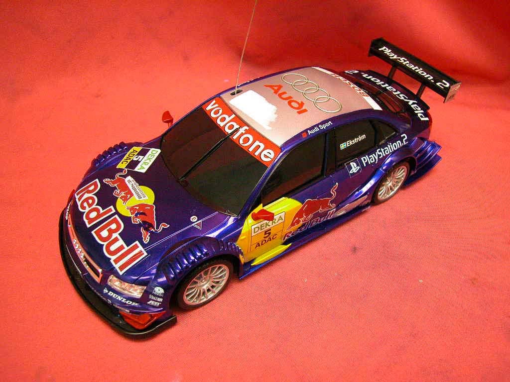
Click to zoom
Application Details
- Equipment Class
- CRR - Superregenerative Receiver
- Date of Grant
- Sep 14, 2005
- Application Purpose
- Original Equipment
- Date of Application
- Sep 14, 2005
- Equipment Note
- RC Car
- Frequency Range
- 49.86000000 - 49.86000000
- Company
- Artin Industrial Co Ltd
- Country
- China
Documents & Files
Document Text
Text extracted from the exhibit documents filed with the FCC. Open a document above to read the original.
Users Manual
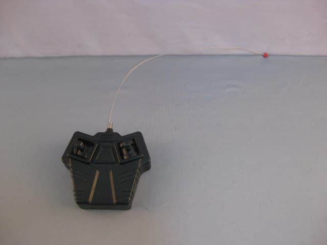
BACKWARD FORWARD ® STOP R L Within this period of time ( 90 days ) we will repair or replace without charge for any manufacturing defects only. This warranty does not cover postage and transportation costs. Accidental damage, misuse, abusive use, crashing, corrosion from dampness, or any other damage related to misuse are not covered by this warranty. This warranty gives you specific legal rights, and you may also have other rights which vary from state to state. ARTIN USA, INC. • ROOM 662, 200 FIFTH AVENUE, NEW YORK, 10010 • FAX: 1-212-633-1926 • HOTLINE: 1-800-97-ARTIN Please keep your sales receipt with the packaging for that period as proof of purchase. ARTIN warrants this product against manufacturer's defects for a period of 90 days from the date of purchase. 1-800-97-ARTIN(27846) Please call our HOTLINE 800 HOTLINE HOURS : 10:00 A.M. - 5:00 P.M. MONDAY - FRIDAY (EXCEPT HOLIDAYS) E-mail: [email protected] 9V9V VEHICLE Removal of the battery cover requires a "phillips head" screwdriver, push the tab on the battery compartment lid and slide the lid back on its hinge. See Figure 3. Make sure the "AA" batteries are new or freshly charged batteries (Do not mix old or used batteries with new batteries). Place the batteries in the battery compartment being sure that the ( + ) and ( – ) poles of the batteries are positioned correctly. See Figure 4. Replace the cover. IMPORTANT! • Do not leave batteries in the vehicle or the transmitter when the toy is not in use. • Do not use old and new batteries together. • Do not mix different types of batteries. Only batteries of the same or equivalent type as recommended are to be used.(e .g. alkaline,Ni-Cd rechargeable, and manganese, or other non-alkaline batteries) • Dispose of old batteries in the proper manner ; do not burn or place near fire. • Non-rechargeable batteries are not to be recharged. • The supply terminals are not to be short-circuited. • Not suitable for children under 3 years of age due to small parts. • Remove rechargeable batteries from the unit before recharging. • Recharging of rechargeable batteries should only be done under adult supervision. • The screwdriver is not a toy. • Do not give the screwdriver to children. • Change the car body by adult only. • Exhausted batteries are to be removed from the toy. BATTERY REQUIREMENTS • This vehicle requires 4 "AA" (LR6) batteries (alkaline or Ni-Cd rechargeable batteries), and one 9V (6LR61) (alkaline) (6F22) (carbon zinc) battery for the transmitter. OPERATING R/C CAR INSTALLING BATTERIES INSTALLING THE BATTERIES TRANSMITTER Removal of the battery cover requires a "phillips head" screwdriver.See Figure 1. After removing this screw, slide the cover downward to remove. Place the 9 V battery in position so that the (+) and (-) are in the proper alignment ads noted.Replace screw to battery cover. See Figure 2. . IMPORTANT! • Do not use vehicle in mud, water, snow, or sand. • Do not play with vehicle in the street. • Do not crash vehicle into any object at high speeds. • When the vehicle slows down install new or freshly charged batteries. • Clean the vehicle with a damp paper towel after operating. (Do not use any chemicals to wipe off car) • Do not leave vehicle in direct sunlight for lengthy periods. Figure 1 Figure 2 Figure 7 THINGS YOU SHOULD KNOW • Radio interference can cause your car to react strangely. • Another vehicle operating on the same frequency can disrupt your controlling the vehicle. • CB's, cellular telephones, two way radios, and other transmitting devices, and high tension wires may cause interference with operation. • Your vehicle can sometimes cause interference with television or even radio reception. Move to another area if you notice this occurrence. WHEEL ALIGNMENT Your steering can be adjusted with the trim switch located on the bottom chassis area. Turn either left or right until you have made the adjustment to maintain a straight path of movement. See Figure 10. Figure 3Figure 4 OPERATING CAR Figure 9 Figure 10 Transmitter : 9V --- 0.05A NATURE POWER OF SUPPLY Receiver : 6V --- 1.8A Figure 8 1. Turn the car switch to "ON". (Located on bottom of car) See Figure 5. 2. Screw the antenna on the top of the transmitter and extend to full length. See Figure 6. 3. Start operating by moving speed control joysticks on the left forward.See Figure 7. 4. Release both control joysticks, the vehicle will stop. See Figure 8. 5. Vehicle steering is controlled by joystick on right by moving left or right .See Figure 9. 6. Do not let vehicle get out of transmitting range as you will then have no control. This range varies due to surroundings. 7. When finished, turn all switches to off position and remove all batteries. Vehicle operation varies from 35 to 45 minutes depending on how the car is used, and the age of the batteries. Figure 5 Figure 6 Radio Control Vehicle Full Function Car Scale: 1:16 MCS: 316501922 WIRE ANTENNA STEERING CONTROL JOYSTICK SPEED CONTROL JOYSTICK Warning: Changes or modifications to this unit not expressly approved by the party responsible for compliance could void the user's authority to operate the equipment.
External Photos
FCC ID: L9G764502R Ophoto1 Ophoto2 FCC ID: L9G764502R Ophoto3 Ophoto4 FCC ID: L9G764502R Ophoto5
Internal Photos
FCC ID: L9G764502R Iphoto1 Iphoto2 FCC ID: L9G764502R Iphoto3 Iphoto4 FCC ID: L9G764502R Iphoto5
Operational Description
FCC ID: L9G764502R Technical Description : The brief circuit description is listed as follows : - Q1 and associated circuit act as Super-regenerative receiver (49.860 MHz). - U1 and associated circuit act as Decoder. - Q2, Q3, Q4, Q5, Q6, Q7 and associated circuit act as Motor Driver for M1. - Q8, Q9, Q10, Q11, Q12, Q13 and associated circuit act as Motor Driver for M2. Antenna Used : A permanent wire antenna has been used.
Schematics
55 44 33 22 11 D D C C B B A A 0.1ux 3 ylnie Note: 1.All resistance values are indicated in "ohm" (Mohm=1,000Kohm ; Kohm=1,000 ohm) 2.All capacitance values are indictaed in "uF" (uF= 1,000nF ; nF=1,000pF) 0.1ux 3 49 . 860 MHz Remote Control Receiver 4 9 RX Model 764502L9G 764502R DAT E 0 NO . REVIS ION BY 2003-4-1 7 ------- ylnie Receiver 49MHz ( PCB SR-7717) 0 1 1 Wednesday, August 31, 2005 DRAWN BY: CHECK BY: APPROVALS BY: DA TE 317002051 -010 317002051 -010 Remote Control Receiver 49 RX 2003-4-1 7 TitleDWG NO. Re v Revise Date: She et of ARTIN Industr ial Co., Ltd. MCS : 6V 6V 6V U1 RX2C 13 2 4 6 7 9 10 11 8 1 15 16 125 143 VDD GND OSCI RIGHT LEFT LDB BACKWARD FORWARD RDB VO2 VO1 VI2 TURBOOSCO VI1SI Q990 14 M1 DRIVING MOTOR R633 0 R1 0 2.2M ANTEN NA R184.7K D13.3 V R1 4 4.7K C218 P C16 0.01 u Q6C2 328 R733 0 Q1 3 805 0 R1122 K R282 0 L1 L-4901 (0.65uH) + C4 4.7u C510 P C120.1u R839 0K R1910 0 R1 5 330 D21N4148 R1 10 K R1 2 36 0K C3 0. 0033u C80.1u Q1 2 805 0 Q7C2 328 Q290 14 Q1 0 855 0 R347 0K L23.3uH + C9220 u C6 0.0 1u Q4A92 8 R2010 0 R1633 0 BA T 6V 2S C380 Q1 C100.1u C1 4 0.0 1u C110 P SW R4 2.2K Q8901 4 Q390 14 Q1 1 855 0 C1 3 0.0 01u R92.2M M2 STEERI NG MOTOR Q5A9 28 R174.7K R53.3 K C70.1 u C12560 P R134.7K
Test Report
• The test results reported in this report shall refer only to the sample actually tested and shall not refer or be deemed to refer to bulk from which such a sample may be said to have been obtained. • This report shall not be reproduced except in full without prior authorization from Intertek Testing Services Hong Kong Limited • The evaluation data of the report will be kept for 3 years from the date of issuance. FCC ID : L9G764502R Artin Industrial Company Limited Application For Certification (FCC ID: L9G764502R) Superregenerative Receiver Sample Description : Remote Control Receiver 49 Rx Model : 764502 0517492 WL/at September 6, 2005 INTERTEK TESTING SERVICES FCC ID: L9G764502R i LIST OF EXHIBITS INTRODUCTION EXHIBIT 1: General Description EXHIBIT 2: System Test Configuration EXHIBIT 3: Emission Results EXHIBIT 4: Equipment Photographs EXHIBIT 5: Product Labelling EXHIBIT 6: Technical Specifications EXHIBIT 7: Instruction Manual EXHIBIT 8: Miscellaneous Information INTERTEK TESTING SERVICES FCC ID: L9G764502R ii MEASUREMENT/TECHNICAL REPORT Artin Industrial Company Limited - MODEL: 764502 FCC ID: L9G764502R September 6, 2005 This report concerns (check one:) Original Grant X Class II Change Equipment Type: Superregenerative Receiver (example: computer, printer, modem, etc.) Deferred grant requested per 47 CFR 0.457(d)(1)(ii)? Yes No X If yes, defer until: date Company Name agrees to notify the Commission by: date of the intended date of announcement of the product so that the grant can be issued on that date. Transition Rules Request per 15.37? Yes No X If no, assumed Part 15, Subpart B for intentional radiator Report prepared by: Wilbur Ng Intertek Testing Services 2/F., Garment Center, 576, Castle Peak Road, HONG KONG Phone: 852-2173-8502 Fax: 852-2742-9149 INTERTEK TESTING SERVICES FCC ID: L9G764502R iii Table of Contents 1.0 General Description..................................................................................................2 1.1 Product Description...............................................................................................2 1.2 Related Submittal(s) Grants..................................................................................2 1.3 Test Methodology..................................................................................................3 1.4 Test Facility...........................................................................................................3 2.0 System Test Configuration ......................................................................................5 2.1 Justification...........................................................................................................5 2.2 EUT Exercising Software.......................................................................................5 2.3 Support Equipment List and Description................................................................5 2.4 Equipment Modification.........................................................................................6 2.5 Special Accessories..............................................................................................6 3.0 Emission Results......................................................................................................8 3.1 Field Strength Calculation......................................................................................9 3.2 Radiated Emission Configuration Photograph......................................................10 3.3 Radiated Emission Data......................................................................................11 4.0 Equipment Photographs ........................................................................................14 5.0 Product Labelling...................................................................................................16 6.0 Technical Specifications ........................................................................................18 7.0 Instruction Manual..................................................................................................20 8.0 Miscellaneous Information.....................................................................................22 8.1 Stabilization Waveform........................................................................................23 8.2 Emissions Test Procedures.................................................................................24 8.2 Emissions Test Procedures (cont'd).....................................................................25 INTERTEK TESTING SERVICES FCC ID: L9G764502R iv List of attached file Exhibit type File Description filename Test Report Test Report report.pdf Operation Description Technical Description descri.pdf Test Setup Photo Radiated Emission radiated photos.doc Test Report Stabilization Waveform superreg.pdf External Photo External Photo external photos.doc Internal Photo Internal Photo internal photos.doc Block Diagram Block Diagram block.pdf Schematics Circuit Diagram circuit.pdf ID Label/Location Label Artwork and Location label.pdf User Manual User Manual manual.pdf INTERTEK TESTING SERVICES FCC ID: L9G764502R 1 EXHIBIT 1 GENERAL DESCRIPTION INTERTEK TESTING SERVICES FCC ID: L9G764502R 2 1.0 General Description 1.1 Product Description The equipment under test (EUT) is a receiver for a RC Car Operating at 49.860 MHz. The EUT is powered by 4 AA batteries. The EUT has an ON/OFF switch. After switch ON, it can be controlled to run forward, backward, turning left and right directions by the controller. The brief circuit description is saved with filename: descri.pdf 1.2 Related Submittal(s) Grants This is a single application for certification of a receiver. The transmitter for this receiver is authorized by Certification procedure with FCC ID: L9G47820T. INTERTEK TESTING SERVICES FCC ID: L9G764502R 3 1.3 Test Methodology The radiated emission measurements were performed according to the procedures in ANSI C63.4 (20…
Text truncated - open the document above for the full version.
Test Setup Photos
INTERTEK TESTING SERVICES Front View Back View
Contact Information
Applicant
Alfred Lee(QA Manager)
Technical Contact
Intertek Testing Services Hong Kong LtdWilbur Ng
[email protected]852-2173-8502
2/F., Garment Centre, · Kowloon · Hong Kong
Non-Technical Contact
Intertek Testing Services Hong Kong LtdWilbur Ng
[email protected]852-2173-8502
Test Firm
Intertek Testing Services Hong KongBilly Chow
Technical Specifications
| # | Rule Parts | Frequency Range | Power Output |
|---|---|---|---|
| 1 | 15B | 49.86 MHz - 49.86 MHz | - |
Other Applications from Artin Industrial Co Ltd
L9G644501
Jul 19, 2010R/C TRANSMITTER BUTTERFLY
Equipment Class
DXX - Part 15 Low Power Communication Device Transmitter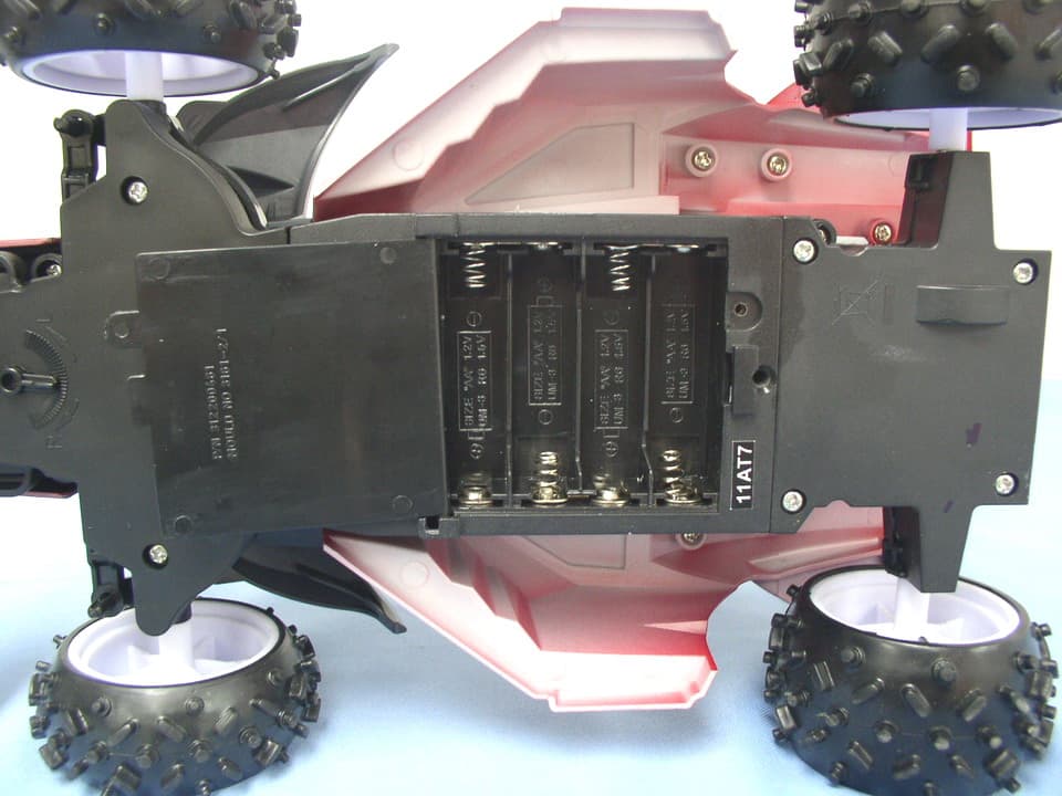
L9G664523R
Jan 28, 2008RC Car
Equipment Class
CRR - Superregenerative Receiver
L9G726502R
Jun 20, 2006RC Car
Equipment Class
CRR - Superregenerative Receiver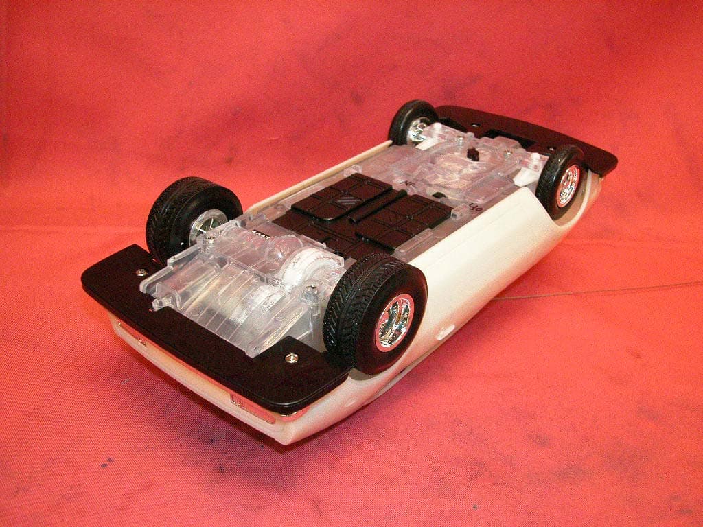
L9G79124R
Jan 24, 2006RC Car
Equipment Class
CRR - Superregenerative Receiver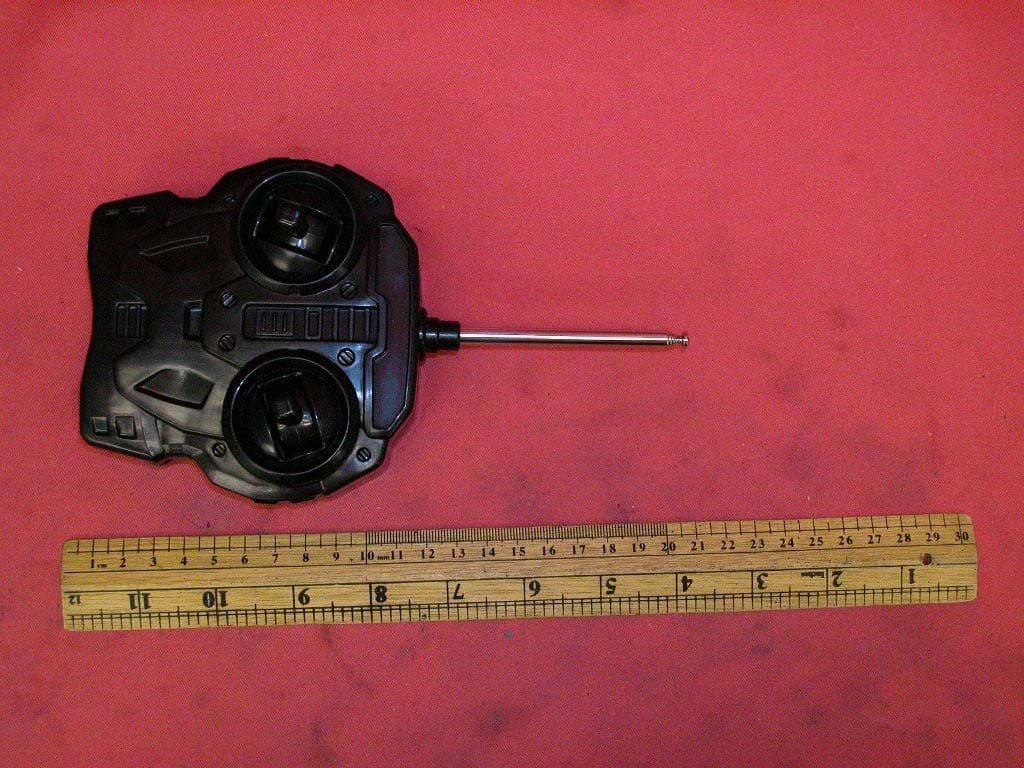
L9G79124T
Jan 24, 2006RC Car
Equipment Class
DXX - Part 15 Low Power Communication Device Transmitter