L9N-7080V2VHF TRANSCEIVER DATA RADIO
AES Corporation
Click to zoom
Application Details
- Equipment Class
- TNB - Licensed Non-Broadcast Station Transmitter
- Date of Grant
- Aug 24, 2000
- Application Purpose
- Original Equipment
- Date of Application
- Jun 20, 2000
- Equipment Note
- VHF TRANSCEIVER DATA RADIO
- Frequency Range
- 218.00000000 - 219.00000000
- Company
- AES Corporation
- Country
- United States
Documents & Files
Document Text
Text extracted from the exhibit documents filed with the FCC. Open a document above to read the original.
Block Diagram
To: Sid Sanders [email protected] From: Tim Harrington [email protected] FCC Equipment Authorization Branch Re: FCC ID: IHDP56LS1 Applicant: Motorola Mobility, Inc. 731 Confirmation Number: TC258043 Date of Original E-Mail: 05/20/2011 Correspondence Reference Number: 101561 Subject: FCC Equipment Authorization System TCB please coordinate with applicant to address the following items 1) the following describes minimal requested filing adjustments and clarifications, based on the exhibits submitted 5/10/11 (SAR revB etc) TCB (and grantee) please carefully proof-read to ensure that the filing has consistent numbers and descriptions across ALL exhibits, and if / where appropriate please do any revisions, small or big, before submitting exhibits to FCC 2) unless we made inadvertant error, the following are pt15 power listings mode f-731 revB suppl op desc emc DTS 2.4 0.101 0.089 0.100 0.087 0.087 DTS 5.8 0.014 0.015 0.020 0.014 0.014 NII 0.024 0.015 0.020 0.015 0.015 DSS 0.011 0.010 0.010 0.010 0.011 the basic practice and procedure for applicants and TCBs is that powers listed must be consistent across an entire FCCID, and/or must have detailed explanations if / where there are differences please revise any applicable exhibits and/or f-731 lines which still have non-negligible differences from measured maximum rated output power as mentioned as part of SAR matters in past TCB conferences, it is suggested that a table such as above is prepared as a first step for every review of a certification application 3) SAR revB includes e.g. "KDB 631391" (e.g. pg 5 of 23) - for this and ALL future filings please revise so that when a KDB number cited is for an inquiry not a publication, please write it as "KDB inquiry XXXXXX", i.e. for this example write as "KDB inquiry 631391" please do text search in all parts of this filing for mention of KDB inquiry numbers, then revise where applicable 4) pg 5-of-33 footnote 2 seems obsolete and/or redundant with text at top of pg 6 - please omit footnote where appropriate 5) as already notified to TCB, the first unnumbered table of pg 6 appears to be "cut/paste" artifact from parallel editing effort for similar but different device ALSO the first paragraph of pg 6 mentions kdb inq. 384782, which seems incorrect please revise ALL parts of this filing where appropriate (e.g. SAR Suppl. pg 4) TCB (and grantee) please carefully proof-read to ensure consistent numbers and descriptions across ALL exhibits, and if / where appropriate please do any revisions, small or big, before submitting exhibits to FCC 6) at first sentence of 2.3, please include "KDB pub. 941225" with this AND any mention in ANY filing documents when referring to FCC procedures e.g. like is done for first sentence of revB sec. 2.4 7) if not in revB already, please add detailed explanation why left-head-cheek has WLAN results for multiple data rates but other head positions do not 8) concerning statements such as the following from revB pg 22 "The cellular phone was also tested in data mode operations. For these tests, a separation distance of 25 mm between the device and the flat phantom was used. The device was tested in the worst-case SAR position and channel configuration from the voice-mode body-worn testing." in absence of detailed explanation concerns are raised that test reductions not in accordance with uniform procedures may have been applied; in general SAR reports need to ensure to apply FCC procedures, i.e. KDB pub 941225, which generally requires treating each mode and position independently in SAR report please add detailed explanations and rationale for what if any 941225 modes and positions were omitted based on this statement; in future filings please ensure to apply uniform procedures 9) whereas from revA to revB the heading rows of tables 23 to 33 were changed from "body worn" to "mobile hotspot", as appropriate please also make same change for captions of those tables 10) at their discretion, TCB can adjust SAR listing format in grant remarks to be consistent with guidance given in Apr 2011 FCC-TCB conference notes 11) SAR suppl. pdf pg 21 is for 9538 bottom-edge, however table at pg 9 has correct associated revB SAR value = 1.03 and position = back surface - please revise for consistency 12) the PCE filing has three exhibits marked short-term confidential (STC), however as we understand, and as consistent with 2/25/11 corresp. in this filing, device is being marketed such that STC is not applicable; please revise as appropriate To: John Lewczak [email protected] From: Tim Harrington [email protected] FCC Equipment Authorization Branch Re: FCC ID: IHDP56LS1 Applicant: Motorola Mobility, Inc. 731 Confirmation Number: TC258043 Date of Original E-Mail: 05/20/2011 Correspondence Reference Number: 101562 Subject: FCC Equipment Authorization System TCB please coordinate with applicant to address the following items 1) the following describes minimal requested filing adjustments and clarifications, based on the exhibits submitted 5/10/11 (SAR revB etc) TCB (and grantee) please carefully proof-read to ensure that the filing has consistent numbers and descriptions across ALL exhibits, and if / where appropriate please do any revisions, small or big, before submitting exhibits to FCC 2) unless we made inadvertant error, the following are pt15 power listings mode f-731 revB suppl op desc emc DTS 2.4 0.101 0.089 0.100 0.087 0.087 DTS 5.8 0.014 0.015 0.020 0.014 0.014 NII 0.024 0.015 0.020 0.015 0.015 DSS 0.011 0.010 0.010 0.010 0.011 the basic practice and procedure for applicants and TCBs is that powers listed must be consistent across an entire FCCID, and/or must have detailed explanations if / where there are differences please revise any applicable exhibits and/or f-731 lines which still have non-negligible differences from measured maximum rated output power as mentioned as part of SAR matters in past TCB conferences, it is suggested that a table such as above is prepa…
Text truncated - open the document above for the full version.
Cover Letter(s)
TIMCO ENGINEERING INC. 849 NW State Road 45 Newberry, Florida 32669 888.472.2424 F 352.472.2030 email: [email protected] 6/21/2000 FCC SUBJECT: FCCID: L9N-7080V2 FOR PART 95F TO WHOM IT MAY CONCERN, This application does not have any frequency stability data because we have been unable to determine what the requirements are for these revised rules. The UUT has a unique connector, it is a TNC with left handed threads. If you have any questions please let me know. Sincerely, Sid Sanders email:[email protected] AES CORPORATION FCC ID : L9N-7080V2 JOB # : 67A0 EXHIBIT # : 11
Cover Letter(s)
TIMCO ENGINEERING, INC. 849 N.W. STATE ROAD 45 P.O. BOX 370 NEWBERRY, FLORIDA 32669 PHONE: 888-472-2424 FAX: 352-472-2030 EMAIL: [email protected] August 21, 2000 Mr. Frank Coperich Federal Communicatio ns Co mmission Authorization and Evaluation Divisin 7435 Oakland Mills Road Columbia, MD 21046 REF: FCC ID: L9N-7080V2 Confirmation #: EA97989 Correspondence ID: 15151 Dear Mr. Coperich: With reference to AES CORPORATION’S FCC ID: L9N-7080V2, and your correspondence ID #: 15151; 1. 2 Watts is fine; thanks. 2. I’ve uploaded two new occupied bandwidth plots – CW and 2 Tone, 1000 Hz, 1300 Hz. The baud rate is 1200. The intended use of this device is for Vehicle Tracking System – as a long range wireless data network. 3. There is no user’s manual for this device as the device is not sold as a “stand alone” device. 4. Frequency stability data has been sent. Should you have any questions or require any further information, please advise. Regards, Sharon Hoffma n/TIMCO ENGINEERING, INC.
Test Report
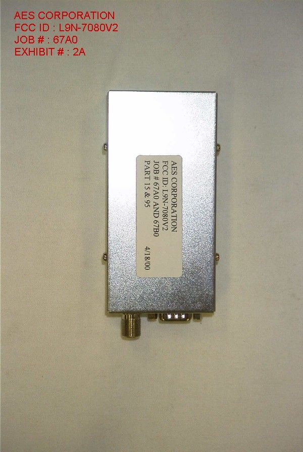
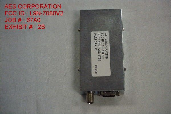
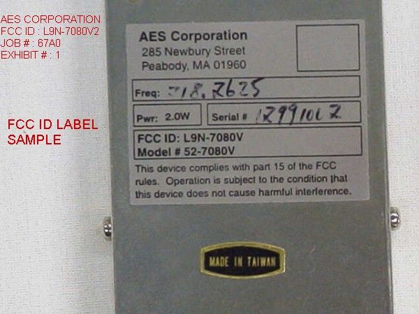
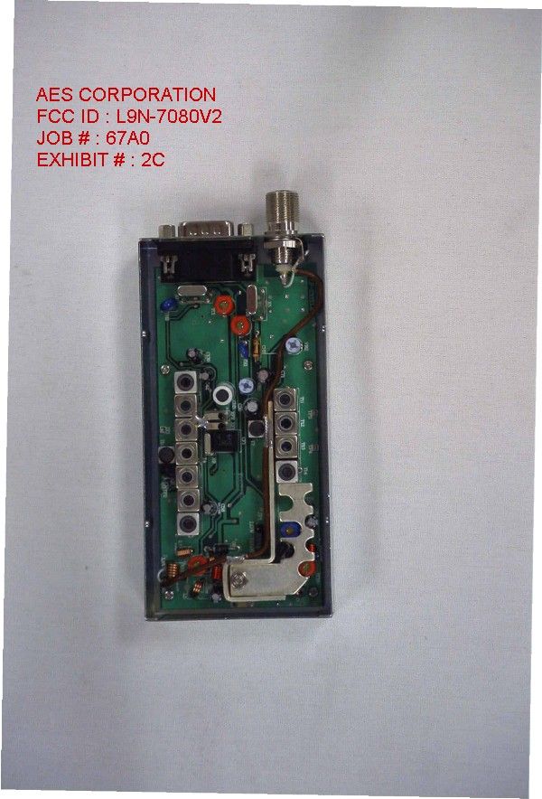
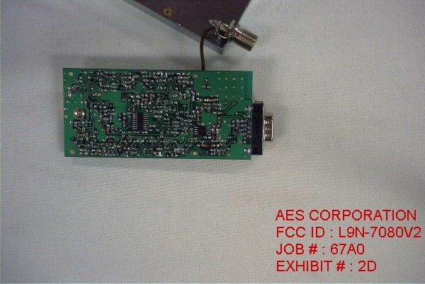
TABLE OF CONTENTS LIST APPLICANT: AES CORPORTATION FCC ID: L9N-7080V2 TEST REPORT: PAGE 1......COVER SHEET - GENERAL INFORMATION & TECHNICAL DESCR. PAGE 2......TECHNICAL DESCRIPTION CONTD. & RF POWER OUTPUT PAGE 3......MODULATION CHARACTERISTICS PAGE 4......OCCUPIED BANDWIDTH PAGE 5......SPURIOUS EMISSIONS AT ANTENNA TERMINALS PAGE 6......FIELD STRENGTH OF SPURIOUS EMISSIONS PAGE 7......METHOD OF MEASURING RADIATED SPURIOUS EMISSIONS PAGE 8......LIST OF TEST EQUIPMENT EXHIBITS CONTAINING: EXHIBIT 1.........FCC ID LABEL SAMPLE AND SKETCH OF FCC ID LABEL LOCATION EXHIBIT 2A........EXTERNAL TOP VIEW PHOTOGRAPH EXHIBIT 2B........EXTERNAL BOTTOM VIEW PHOTOGRAPH EXHIBIT 2C........INTERNAL COMPONENT SIDE PHOTOGRAPH EXHIBIT 2D........INTERNAL SOLDER SIDE PHOTOGRAPH EXHIBIT 3.........BLOCK DIAGRAM EXHIBIT 4.........SCHEMATIC EXHIBIT 5A-5C.....TUNING PROCEDURE EXHIBIT 6.........CRYSTAL SPECIFICATION EXHIBIT 7.........THEORY OF OPERATION EXHIBIT 8A........OCCUPIED BANDWIDTH PLOT - CW EXHIBIT 8B........OCCUPIED BANDWIDTH PLOT EXHIBIT 9.........AUDIO FREQUENCY RESPONSE GRAPH EXHIBIT 10A.......MODULATION LIMITING - 300 Hz EXHIBIT 10B.......MODULATION LIMITING - 1000 Hz EXHIBIT 10C.......MODULATION LIMITING - 3000 Hz EXHIBIT 11........LETTER OF EXPLAINATION APPLICANT: AES CORPORTATION FCC ID: L9N-7080V2 DATE: 8 MAY 2000 REPORT #: T:\CUS\A\AES\AES67A0\67A0.RPT PAGE: TABLE OF CONTENTS GENERAL INFORMATION REQUIRED FOR TYPE ACCEPTANCE 2.1033 (C) (1) (2) AES CORPORTATION will sell the FCCID: L9N-7080V2 VHF transciever in quantity, for use under FCC RULES PART 95 2.1033 (C) TECHNICAL DESCRIPTION (3) The user manual is included as Exhibit 11. (4) ALLOWED AUTHORIZED BANDWIDTH = 20.0KHz. Bn = 2M + 2DK M = 3000 D = 3.2 K (Peak Deviation) K = 1 Bn = 2(3.0K) + 2(3.2K)(1) = 6.0K + 6.4K =12.4 K Type of Emission: 12K4F3E ALLOWED AUTHORIZED BANDWIDTH = 20.0KHz. 2.1033(C)(5) Frequency Range: 218-219 MHz (6) Power Range and Controls: This UUT has two(2) power ranges, 2.0 watts (7) 2,1033(c)(b) Maximum Output Power Rating: 5.0Watts into a 50 ohm resistive load. (8) DC Voltages and Current into Final Amplifier: POWER INPUT FINAL AMPLIFIER ONLY POWER OUT 2.0 Vce Volts 13.8v Ice Amps 0.55 Pin Watts 7.59 APPLICANT: AES CORPORTATION FCC ID: L9N-7080V2 DATE: 8 MAY 2000 REPORT #: T:\CUS\A\AES\AES67A0\67A0.RPT PAGE #: 1 2.1033(c)(9) The tune-up procedure is included as Exhibit # 5A-5C. 2.1033(c)(10) A schematic in included as Exhibit # 4. 2.1033(c)(11) Photograph or drawing of the label showing the FCC ID is shown in Exhibit # 1 and the location of the label is shown in Exhibit # 1. 2.1033(c)(12) Photographs completely documenting the radio are shown in Exhibit # 2A-2D. 2.1033(c)(13) N/A This is for devices that use digital modulation. 2.1033(c)(14) The data required by 2.1046 through 2.1057 follows; 2.1046(a) RF power output. The test procedure used was TIA/EIA-603 S2.2.1. RF power is measured by connecting a 50 ohm, resistive wattmeter to the RF output connec- tor. With a nominal battery voltage of 12.5V, and the transmitter properly adjusted the RF output measures: INPUT POWER: (13.8V)(0.55) = 7.59Watts OUTPUT POWER: 2.0 Watts Efficiency: 26% 2.1046(a) RF power output. The test procedure used was TIA/EIA-603 S2.2.1. /---------------\ | Dummy | /-| Microphone | | | | | \---------------/ | | /------------\ /------------\ /---------\ | | | | STANDARD | | RF | | | Transmitter|-----------| TRANSMITTER|---| POWER | \-| under test | | LOAD | | METER | \------------/ \------------/ \---------/ APPLICANT: AES CORPORTATION FCC ID: L9N-7080V2 DATE: 8 MAY 2000 REPORT #: T:\CUS\A\AES\AES67A0\67A0.RPT PAGE #: 2 2.1047(a) Modulation characteristics: AUDIO FREQUENCY RESPONSE The audio frequency response was measured in accordance with TIA/EIA Specification TIA/EIA-603 S2.2.6.2.1. The audio frequency response curve is shown in Exhibit # &audfrres&. 2.1049 AUDIO LOW PASS FILTER Not applicable, 95 Subpart F. 2.1049 AUDIO INPUT VERSUS MODULATION The audio frequency input versus deviation was measured in accordance with TIA/EIA Specification 603 S2.2.6.2.1. with the follow- ing exceptions; starting with 1000Hz the input was increased well beyond the deviation changing. This measurement was repeated for the band limits and any frequency deemed appropriate. See Exhibit # 10A-10C. /---------------\ /----------\ /----------\ | Dummy | | Audio | | RMS | /-| Microphone |--| Generator| /-| VOLTMETER| | | | \----------/ | \----------/ | \---------------/ | |----------------------------------/ | /------------\ /------------\ /---------\ | | | | STANDARD | | Test | | | Transmitter|-----------| TRANSMITTER|---| Receiver| \-| under test | | PROBE | | | \------------/ \------------/ \---------/ 1.The test receiver audio bandwidth was <50Hz to >20,000Hz. APPLICANT: AES CORPORTATION FCC ID: L9N-7080V2 DATE: 8 MAY 2000 REPORT #: T:\CUS\A\AES\AES67A0\67A0.RPT PAGE #: 3 2.1049 Occupied bandwidth: 90.210 (b) (1) Zero dB on any frequency within the authorized frequen cy segment. (2) At least 28dB on any frequency removed from the midpoint of the assigned frequency segment by more than 250kHz up to and including 750kHz. (3) At least 35dB on any frequency removed from the mid- point of the assigned frequency segment be more than 750kHz up to and incluuding 1250kHz. (4) At least 43 + 10 log(P) dB on any frequency remove from the midpoint of the assigned frequency segment be more than 1250kHz. See Exhibit # 8A-8B. 2.1049 Occupied bandwidth: Using TIA/EIA 2.2.11 sideband Spectrum TIA/EIA-603 S2.2.11 was used to measure the occu pied bandwidth. Plots were made of the highest frequency and at 2500Hz. Data in the plots show that all sidebands beyond the authorized bandwidth are less than 0.5% of the unmodu- lated carrier. The plots show the transmitter modulation with; For 25.0KHz Channel spacing no modulation, 2500Hz, 3000Hz At each of the tone input was adjusted for 50% modulation plus 16 dB. The spectrum analyzer was set with the unmodu- lated carrier at the top of the s…
Text truncated - open the document above for the full version.
Test Report
AES Corporation L9N-7080V2 0 10 20 30 40 50 60 70 80 90 100 100100010000 Frequency rms mVolts audio response AES CORPORATION FCC ID : L9N-7080V2 JOB # : 67A0 EXHIBIT # : 9
Test Report
Modulation Limiting AES Corporation L9N-7080V2 0 1000 2000 3000 4000 5000 050100150200250300 rms mVolts Deviation 300 Hz AES CORPORATION FCC ID : L9N-7080V2 JOB # : 67A0 EXHIBIT # : 10A
Test Report
Modulation Limiting AES Corporation L9N-7080V2 0 500 1000 1500 2000 2500 3000 3500 4000 050100150200250300 rms mVolts Deviation 1000 Hz AES CORPORATION FCC ID : L9N-7080V2 JOB # : 67A0 EXHIBIT # : 10B
Test Report
Modulation Limiting AES Corporation L9N-7080V2 0 500 1000 1500 2000 2500 3000 3500 050100150200 rms mVolts Deviation 3000 Hz AES CORPORATION FCC ID : L9N-7080V2 JOB # : 67A0 EXHIBIT # : 10C
Contact Information
Applicant
Michael J Sherman(President)
Technical Contact
Timco Engineering, Inc.Eric F Dobson
[email protected]888-472-2424
P.O. Box 370 · Newberry, Florida · United States
Non-Technical Contact
Timco Engineering, Inc.Eric F Dobson
[email protected]888-472-2424
Test Firm
Timco Engineering, Inc.S Sanders
Technical Specifications
| # | Rule Parts | Frequency Range | Power Output | Emission | Tolerance |
|---|---|---|---|---|---|
| 1 | 95F | 218 MHz - 219 MHz | 2 W | 10K2F2D | 50.0000000000 ppm |
Other Applications from AES Corporation

L9N-7085PUE5
Jun 09, 2020RF DATA RADIO
Equipment Class
TNB - Licensed Non-Broadcast Station Transmitter
L9N-7880LC2B
Nov 22, 2012RF DATA RADIO
Equipment Class
TNB - Licensed Non-Broadcast Station Transmitter
L9N-7880LC2
Apr 11, 2011RF DATARADIO
Equipment Class
TNB - Licensed Non-Broadcast Station Transmitter
L9N-7350UE5
Feb 04, 2010Data Transceiver
Equipment Class
TNB - Licensed Non-Broadcast Station Transmitter
L9N-7880-A
Dec 13, 2004UHF Data Transceiver Module
Equipment Class
TNB - Licensed Non-Broadcast Station Transmitter