LB32G4-TX-MODAudio/Video Transmitter Module
Veccom Co Ltd
Click to zoom
Application Details
- Equipment Class
- DXX - Part 15 Low Power Communication Device Transmitter
- Date of Grant
- Jan 28, 1999
- Application Purpose
- Original Equipment
- Date of Application
- Nov 02, 1998
- Equipment Note
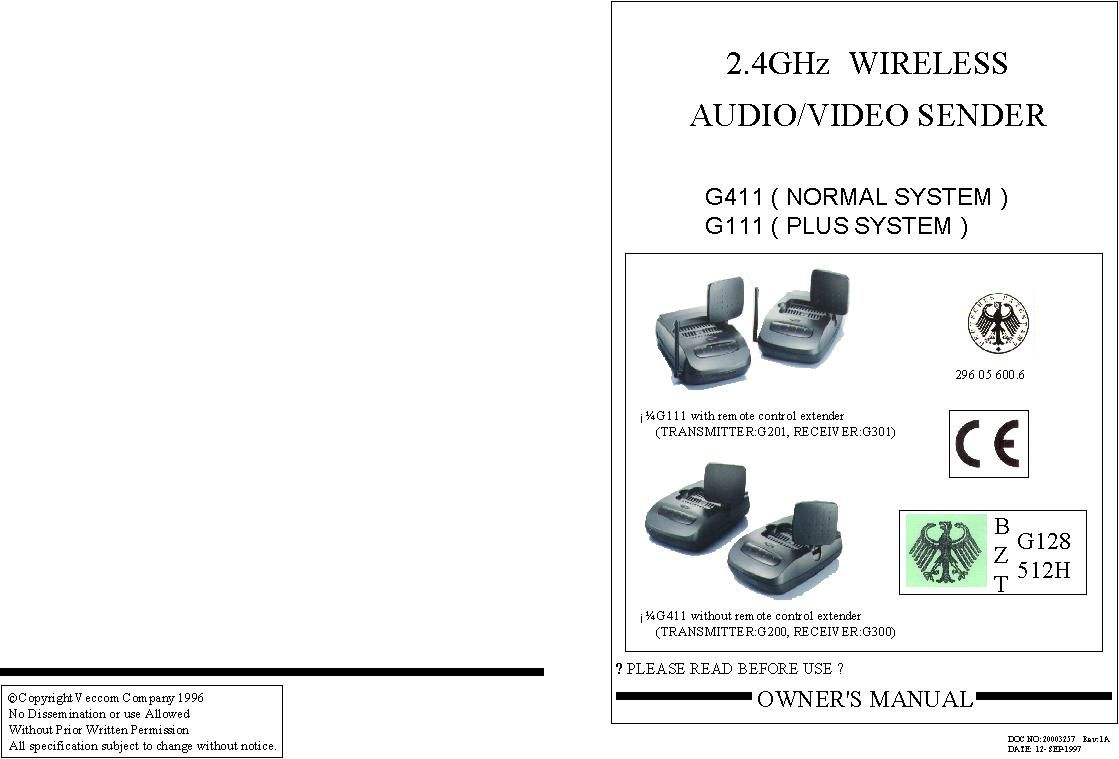
- Audio/Video Transmitter Module
- Frequency Range
- 2415.60000000 - 2466.80000000
- Company
- Veccom Co Ltd
- Country
- Taiwan
Documents & Files
Document Text
Text extracted from the exhibit documents filed with the FCC. Open a document above to read the original.
Attestation Statements
FCC ID: LB32G4-TX-MOD
Attestation Statements
FCC ID: LB32G4-TX-MOD
Attestation Statements
FCC ID: LB32G4-TX-MOD
Attestation Statements
1100 E. Chalk Creek Rd. Coalville, UT 84017 Voice 435.336.4433, Fax 435.336.4436 FCC ID LB32G4-TX-MOD Electronic Filing Number: EA92198 Correspondence Reference Number: 5578 Attestation for module approval.
Attestation Statements
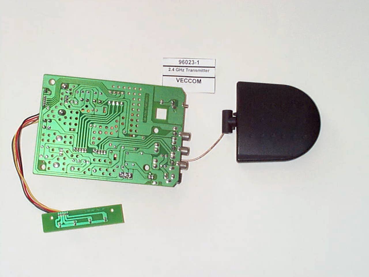
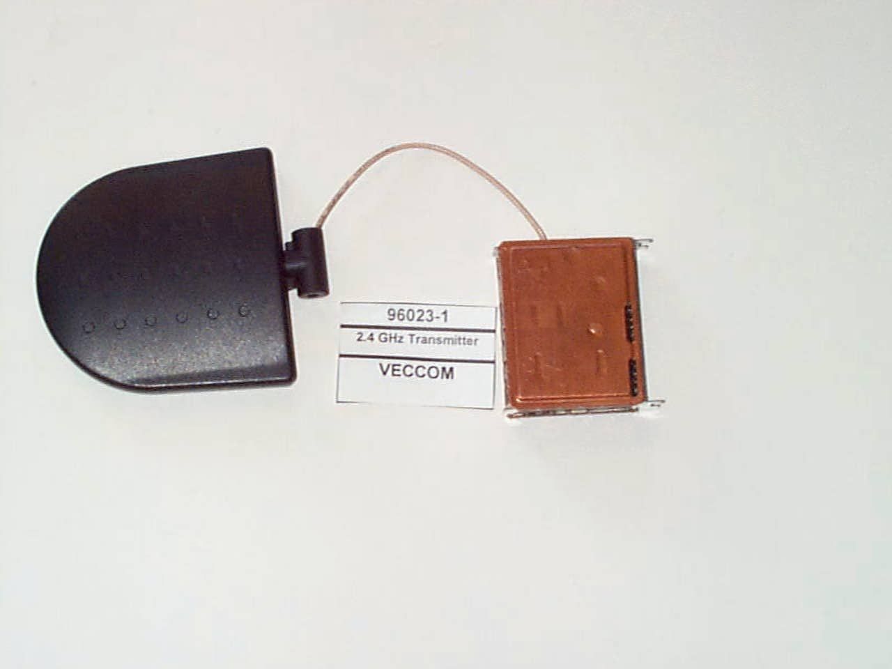
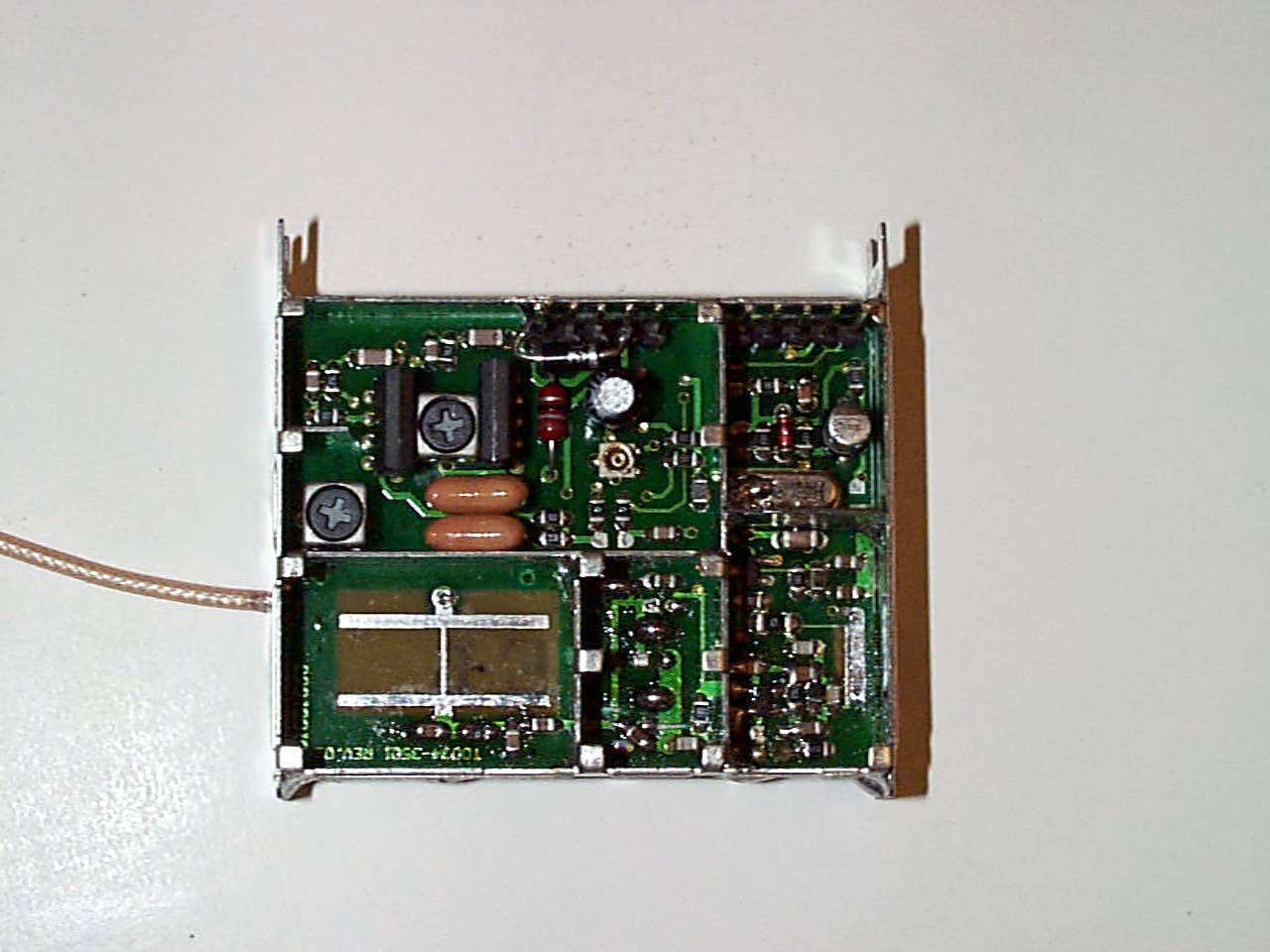
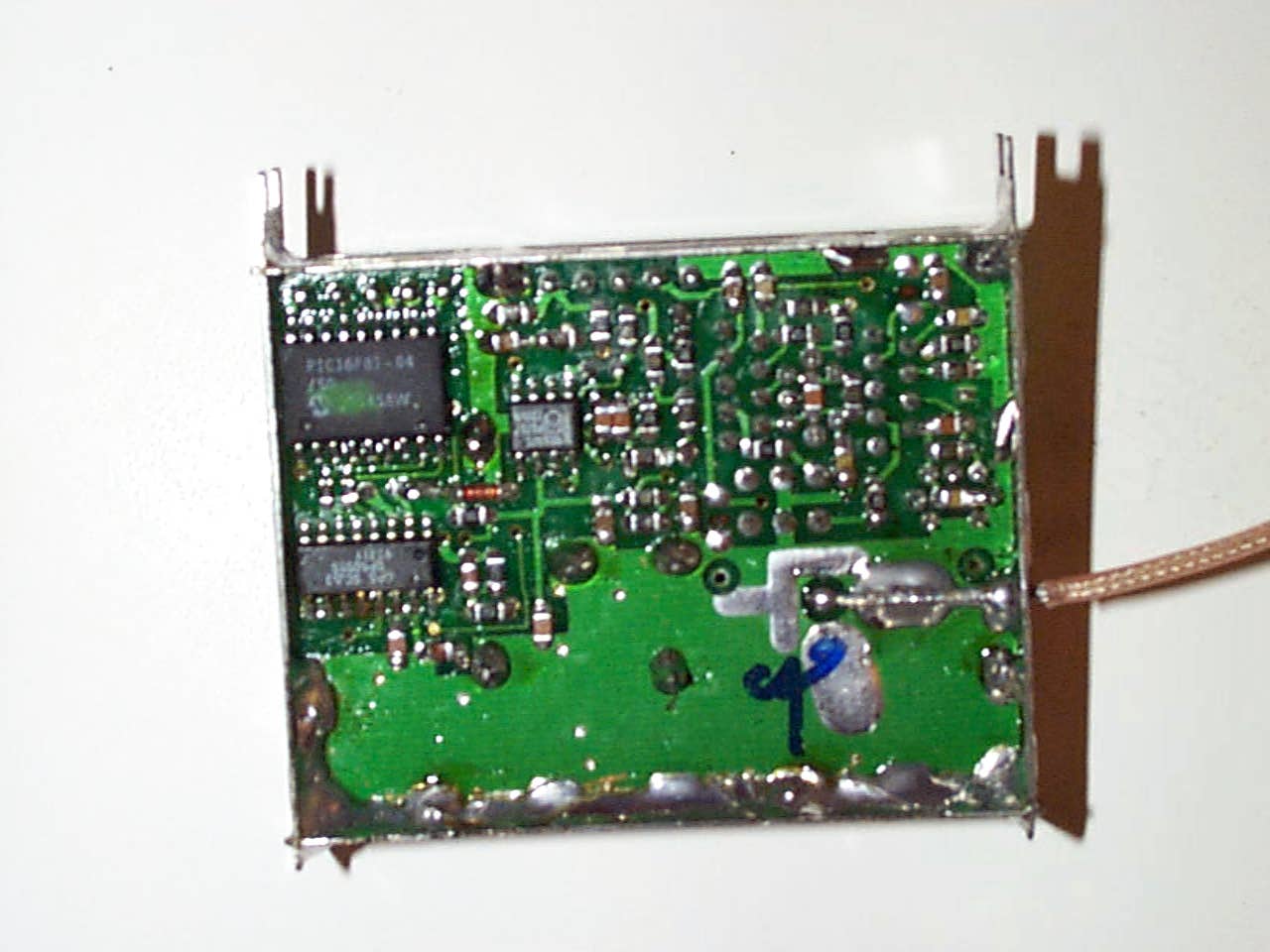
1100 E. Chalk Creek Rd. Coalville, UT 84017 Voice 435.336.4433, Fax 435.336.4436 January 25, 1999 Greg Czumak FCC Subject: FCC ID LB32G4-TX-MOD 731 Confirmation Number EA92198 Correspondence Reference Number 5578 Dear Greg, In reply to each item in your Jan. 15, 1999, e-mail which is attached at the end of this document. 1. Requirement for module approval. 1. Per our photos provided in the report the RF section is shielded and will be remain the same, regardless of enclosure. 2. Buffered Modulation inputs (Audio and video) are provided inside the shielded RF section. 3. Power supply regulation is provided by the PCB external to the RF Section. This PCB will not change and is part of the module approval. 4. Antenna is not removable. 5. Was tested in stand-alone configuration. 6. FCC ID is labeled on the module and a second label will be applied to the out side of each enclosure. An example was sent as through the “Add attachment” button of the FCC Electronic Filing page. 2. The RF portion and power regulation board with audio and video inputs is being authorized as a module. Please see attestation file for this from Veccom sent through the add attachment button of the FCC electronic filing page. 3. In the future we will use the EUT actual tuning range. This device does not fall under section 15.247 and as such should not pose a threat to RF Safety. Thank you, Rick Linford Facility Manager/Regulatory Engineer DNB Engineering, Inc (UT) 1100 E. Chalk Creek Rd. Coalville, UT 84017 Voice 435.336.4433, Fax 435.336.4436 To:Rick Linford, DNB Engineering, Inc. From:Greg Czumak [email protected] FCC Application Processing Branch Re:FCC ID LB32G4-TX-MOD Applicant:Veccom Co Ltd Correspondence Reference Number:5578 731 Confirmation Number:EA92198 Date of Original E-Mail:01/15/1999 1.Copied below is our modular approval policy. Please specifically state how the EUT meets each of the criteria listed. I note that the required second label has not been submitted. Please be sure to do that. 2.Please verify that both the RF portion and the power regulation board, with audio/video inputs, are being authorized as a module (and not the RF section alone). 3.FYI: the tuning range which you fill out should indicate the actual tuning range of the EUT, and not simply identify the band in which it will operate. This has been Commission policy for many years now. There are no official FCC Rules that permit authorization of a transmitter as a module but the following standards have been uniformly applied as a Commission policy in support of industry needs. For a module to be approved, it must satisfy the following requirements: (1)a modular transmitter must have its own RF shielding (2)a modular transmitter must have buffered modulation/data inputs (if such inputs are provided) (3)a modular transmitter must have it own power supply regulation (4)a modular transmitter must have an antenna which complies with the requirements of Section 15.203 (permanently attached or employs a “unique” antenna coupler) (5)a modular transmitter must be tested in a stand-alone configuration, i.e., the antenna, AC or DC power and data input/output lines must be connected to the module but, the module must not be inside another case during testing (6)a modular transmitter must be labelled with its own FCC ID number, and if the FCC ID is not visible when the module is installed inside another device, then the outside of the device into which the module is installed must also display a label referring to the enclosed module. This exterior label can use wording such as the following: “Contains Transmitter Module FCC ID: XYZMODEL1” or “Contains TXFCC ID: XYZMODEL1.” The exact wording is not specified in our Rules (since modules are not specifically addressed), so you may use similar wording which expresses the same meaning. The only other issue that may need to be addressed is the RF exposure limit mentioned in Section 15.247(b)(4) of the rules for spread spectrum transmitter operation. All other sections of Part 15 do not possess enough power to present a problem with the RF exposure limits. However, a spread spectrum transmitter operated at permissible power levels may pose a threat to RF safety, therefore, compliance with the RF exposure limits must be addressed for spread spectrum transmitter modules. Please note that if modular approval is granted for a device, the grant of authorization will specifically use the term “module.”
Cover Letter(s)
1100 E. Chalk Creek Rd. Coalville, UT 84017 Voice 435.336.4433, Fax 435.336.4436 November 4, 1998 Reference: FCC ID LB32G4-TX-MOD and From 731 Confirmation Number EA92198 To Whom It May Concern: This application is to certify the power regulation board and RF module as a module to be installed in different enclosures. If you have any questions please direct them to my attention by voice or fax at the number shown above or e-mail me at [email protected]. Thank you, Rick Linford Facility Manager/Regulatory Engineer DNB Engineering, Inc (UT)
ID Label/Location Info
FCC ID: LB32G4-TX-MOD
ID Label/Location Info
1100 E. Chalk Creek Rd. Coalville, UT 84017 Voice 435.336.4433, Fax 435.336.4436 FCC ID LB32G4-TX-MOD Electronic Filing Number: EA92198 Correspondence Reference Number: 5578 Sample of enclosure label for module.
Schematics
FCC ID: LB32G4-TX-MOD
Schematics
FCC ID: LB32G4-TX-MOD
Schematics
FCC ID: LB32G4-TX-MOD
Schematics
FCC ID: LB32G4-TX-MOD
Test Report
FCC ID: LB32G4-TX-MOD
Test Report
FCC ID: LB32G4-TX-MOD
Test Report
Re: N6RFHSS-900 731 Confirmation Number: EA91734 Correspondence ID: 4399 November 5 th 1998 1) In order to comply with the RF Safety requirements. The manual for the N6RFHSS-900 contains the statement "Warning: prolonged human exposure to antenna at distances closer than 20 cm(8in), could exceed FCC MPE(maximum permissible exposure) limits." 2) The antenna connector is a non-standard reverse gender SMA connector 3) In order to ensure Class A use, we will address the marketing following restrictions. a) I verify that the device will not be sold to the General Public and will not be sold to distributors that sell to the General Public. b) I verify that OEM customers will be notified that end user products based on these modules must be commercial in nature. c) I verify that the following will be placed in the manual. "This module has been tested to class A FCC limits. It's use is limited to commercial applications without further FCC compliance testing. This module cannot be resold to the general public." 4) Modules will be provided with a second label that must be affixed to the outside of the enclosure of the end product for identification purposes. An example of the label will be sent with this document. 5) The text "Place the label in a conspicuous area on the enclosure of the end product." Will be included in the OEM manual. Sincerely John Whitlock
Test Report
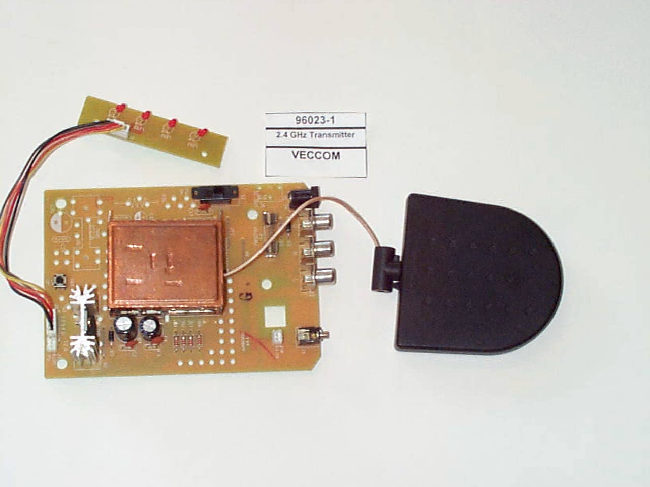
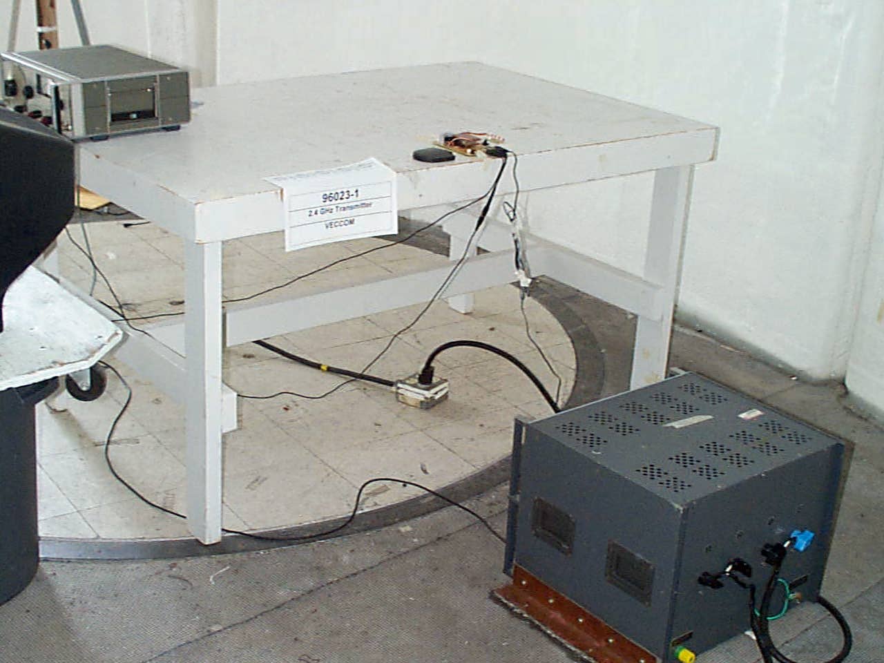
FCC ID: LB32G4-TX-MOD DATE: SEPT. 30 – OCT. 2, 1998 REPORT # 96023-1 1 DNB ENGINEERING, INC. CERTIFICATION FOR INTENTIONAL RADIATOR per Part 15 Subpart C (CFR 47, 15,203, 15.207, 15.209 & 15.249) EUT: 2.4 GHz TRANSMITTER PREPARED FOR APPLICANT: VECCOM 3 TZE Chiang 1 Road Chingli Industrial Park Tao Yuan Hsien, Taiwan, ROC REPORT # 96023-1 Test Date: Sept. 30 – Oct. 2, 1998 Prepared By: DNB ENGINEERING, INC. 1100 East Chalk Creek Rd. Coalville, Utah 84017 Tel: 1(435) 336-4433 FCC ID: LB32G4-TX-MOD DATE: SEPT. 30 – OCT. 2, 1998 REPORT # 96023-1 2 Revision Letter Number of Pages Page No. of Rev. DescriptionDate ADocument Release FCC ID: LB32G4-TX-MOD DATE: SEPT. 30 – OCT. 2, 1998 REPORT # 96023-1 3 TRANSMITTAL SUMMARY Unit tested: 2.4 GHz TRANSMITTER Model #: 2G4 TX Module FCC ID: LB32G4-TX-MOD Specifications: ANSI C63.4 (1992) and CFR 47 FCC part 15 Subpart C Purpose of Report: This report was prepared to document the status of the 2.4 GHz TRANSMITTER with requirements of the standards listed above. Requirements not applicable to EUT Part 15.37 - Not applicable Emergency Broadcast System - Not applicable Spread Spectrum Exhibit - Not applicable Scanning Receiver - Not applicable Test Summary The EUT’s compliance status according to the tests performed is as follows. REQUIREMENTSSTATUS FCC part 15 Subpart C per 15.203, 15.207, 15.209 & 15.249 COMPLIANT The report shall not be reproduced, except in full, without the written approval of DNB ENGINEERING, INC. Results contained in this report relate only to the item tested. FCC ID: LB32G4-TX-MOD DATE: SEPT. 30 – OCT. 2, 1998 REPORT # 96023-1 4 CERTIFICATION OF TEST DATA - per 2.911(d) This report, containing emissions test data and evaluations, has been prepared by an independent electromagnetic compatibility laboratory, DNB ENGINEERING, in accordance with the applicable specifications and instructions required per the Introduction. DNB Engineering has been evaluated to do these tests by the American Association for Laboratory Accreditation, A2LA. The data evaluation and equipment configuration presented herein are a true and accurate representation of the measurements of the test emissions characteristics as of the dates and at the times of the test under the conditions herein specified. Equipment Tested:2.4 GHz TRANSMITTER Model #:2G4 TX Module FCC ID#:LB32G4-TX-MOD Dates of Test:Sept. 30 – Oct. 2, 1998 Test Performed: ____________________________________________ Gaylord Alexander BuchananDate Test Technician Test Report Reviewed: ____________________________________________ Rick LinfordDate Facility Manager Regulatory Engineer FCC ID: LB32G4-TX-MOD DATE: SEPT. 30 – OCT. 2, 1998 REPORT # 96023-1 5 TABLE OF CONTENTS 1. INTRODUCTION................................................................................................................................................... 6 1.1 A DMINISTRATIVE DATA PER 2.1033(A) AND 2.911(C)................................................................................................ 6 1.1.1 REQUEST FOR CERTIFICATION Per 2.1033(b)1:...................................................................................... 6 1.2 R ELATED SUBMITTALS/GRANTS................................................................................................................................. 6 1.3 P URPOSE OF TESTS................................................................................................................................................... 6 2. TEST DESCRIPTION............................................................................................................................................. 7 2.1 T EST CONFIGURATION.............................................................................................................................................. 7 2.2 E QUIPMENT DESCRIPTION........................................................................................................................................ 7 2.2.1 Mode of Operation .......................................................................................................................................... 7 2.3 A NTENNA REQUIREMENT - PER 15.203...................................................................................................................... 7 2.4 S CHEMATICS............................................................................................................Error! Bookmark not defined. 2.4.1 Circuit Description - per 2.1033(b)4 ............................................................................................................... 8 2.5 P HOTOGRAPH OF EUT - PER 2.1033(B)(7)............................................................................................................... 9 3. EMISSIONS FCC PART 15 ................................................................................................................................ 10 3.1 R ADIATED EMISSIONS TEST SETUP AND PROCEDURE - PER 2.1033(B)(6) PER 2.947(A)........................................... 10 3.1.1 Spurious Radiation Test Site Per 2.1033(b)6 .............................................................................................. 10 3.1.2 Example Of Typical Calculation Per 2.1033(b)6 ........................................................................................ 12 3.1.3 Diagram of Test Setup - per 2.1033(b)5 ........................................................................................................ 13 3.1.4 Field Strength of Intentional Radiator Inside of Band .................................................................................. 14 3.1.5 Emissions Radiated Outside of Band............................................................................................................. 15 3.1.6 Occupied Bandwidth ..................................................................................................................................... 16 3.1.7 Photograph of Radiated Test …
Text truncated - open the document above for the full version.
Test Report
CONDUCTED EMISSIONS Location #2 FCC Part 15 Class B Client:VECCOMFile #96023-1 Date :30-Se p-98Engr.:Buck Buchanan Meas Type LISNCableTotalFCC Ave Freq.Meas'd Factors Factors FactorsTotalLimitDeltaQP Phase HP / (MHz)(dBuV)(dB)(dB)(dB)(dBuV)(dBuV)(dB)Peak N,P1,P2,P3 R&S 0.00.00.00.000.00.000.0 0.45026.100.10.20.326.4048.0-21.60QPNeutralR&S 0.50024.800.10.20.325.1048.0-22.90QPNeutralR&S 1.34510.800.10.30.411.2048.0-36.80QPNeutralR&S 0.45031.100.10.20.331.4048.0-16.60QPPhase 1R&S 0.61327.200.10.20.327.5048.0-20.50QPPhase 1R&S 0.70029.400.10.30.429.8048.0-18.20QPPhase 1R&S 0.80030.200.10.10.230.4048.0-17.60QPPhase 1R&S 0.51729.900.10.20.330.2048.0-17.80QPNeutralR&S 2.5792.600.20.40.63.2048.0-44.80QPNeutralR&S 0.45035.200.10.20.335.5048.0-12.50QPPhase 1R&S 0.60028.400.10.20.328.7048.0-19.30QPPhase 1R&S 0.70032.000.10.30.432.4048.0-15.60QPPhase 1R&S 3.0004.500.20.50.75.2048.0-42.80QPPhase 1R&S Rep : Mary Ann Ma System: 2.4 GHz Transmitter Comments 0.0 Run 1.0 (no modulation, video/audio) QP Rollin g spikes QP Rollin g spikes QP Rollin g spikes QP Rollin g spikes QP Rollin g spikes QP Rollin g spikes QP Rollin g spikes Run 1.1 (video & audio present) QP Rollin g spikes QP Noise floor QP Rollin g spikes QP Rollin g spikes QP Rollin g spikes QP Noise floor
Test Report
FCC ID: LB32G4-TX-MOD
Test Report
FCC ID: LB32G4-TX-MOD
Contact Information
Applicant
Steven Chang(Director)
886 3 451-5217Fax: 886 3 451-5216
Technical Contact
DNB Engineering, Inc.Rick Linford
[email protected]435-336-4433
1100 E. Chalk Creek Rd. · Coalville, Utah · United States
Technical Specifications
| # | Rule Parts | Frequency Range | Power Output |
|---|---|---|---|
| 1 | 15C | 2.42 GHz - 2.47 GHz | - |
Other Applications from Veccom Co Ltd

LB3-AVSENDER1
Feb 25, 1999DXX - Part 15 Low Power Communication Device Transmitter
Equipment Class
DXX - Part 15 Low Power Communication Device TransmitterLB3AO-SENDER
Sep 10, 1998JBP - Part 15 Class B Computing Device Peripheral
Equipment Class
JBP - Part 15 Class B Computing Device Peripheral
LB3AC-SENDER
Jun 30, 1998DXX - Part 15 Low Power Communication Device Transmitter
Equipment Class
DXX - Part 15 Low Power Communication Device TransmitterLB3AI-RECEIVER
Dec 01, 1997Transmitter for Video Transmitting System
Equipment Class
DXX - Part 15 Low Power Communication Device TransmitterLB3AI-TRANSMITTER
Dec 01, 1997Video Transmitter w/VGA Port
Equipment Class
DXX - Part 15 Low Power Communication Device Transmitter