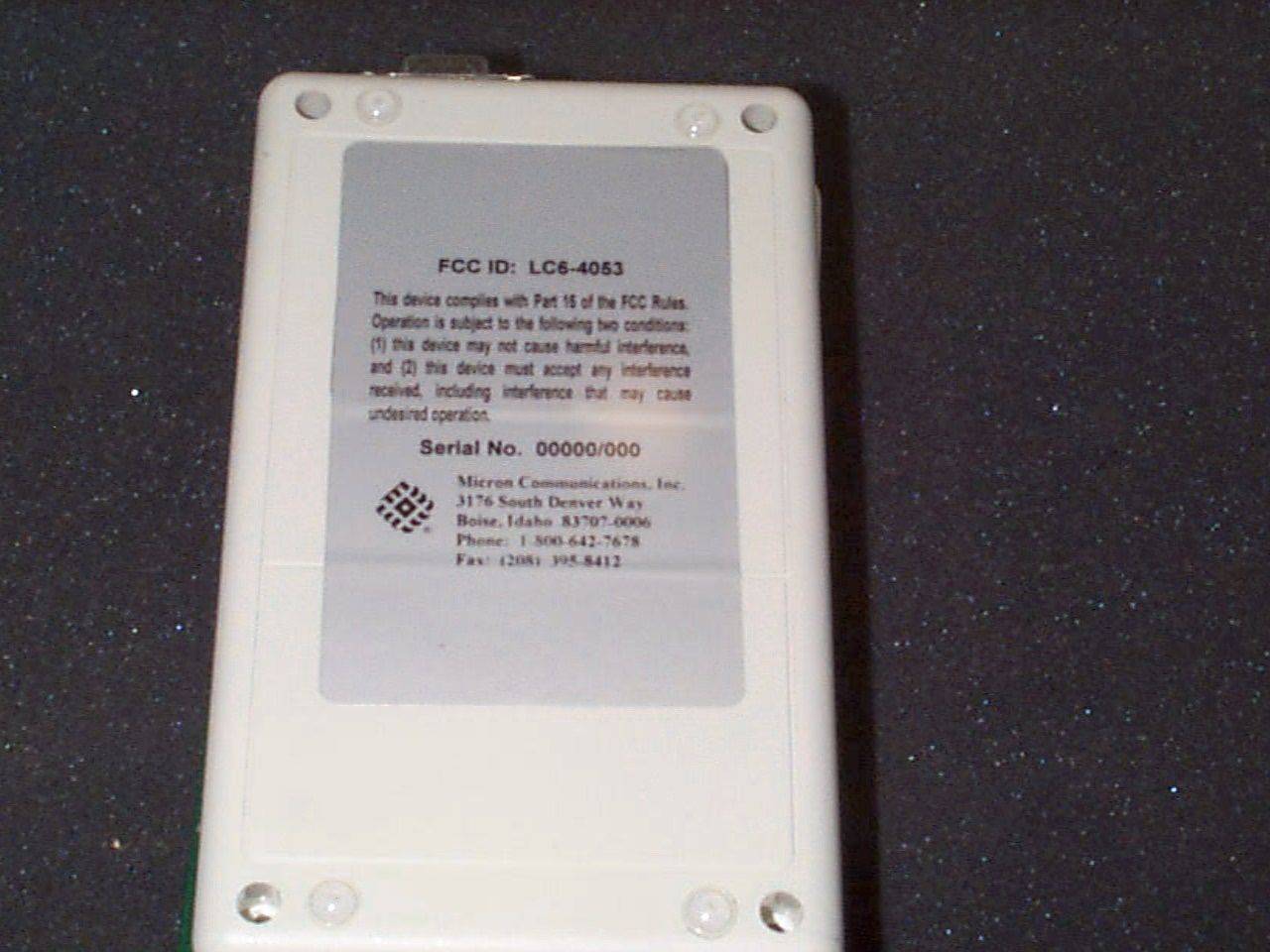
LC6-4053Industrial Reader
Micron Communications Inc
Click to zoom
Application Details
- Equipment Class
- DCD - Part 15 Low Power Transmitter Below 1705 kHz
- Date of Grant
- Jan 19, 1999
- Application Purpose
- Original Equipment
- Date of Application
- Nov 17, 1998
- Equipment Note
- Industrial Reader
- Frequency Range
- 0.12300000 - 0.12700000
- Company
- Micron Communications Inc
- Country
- United States
Documents & Files
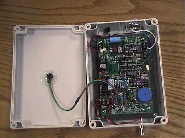
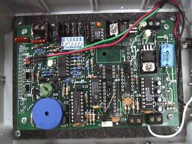
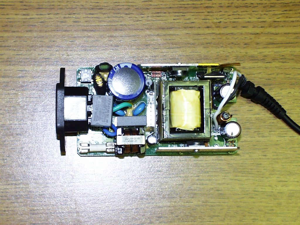
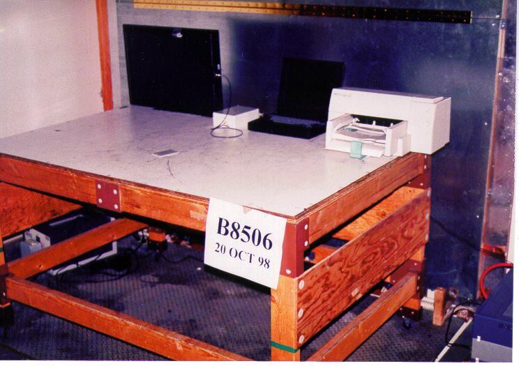
Document Text
Text extracted from the exhibit documents filed with the FCC. Open a document above to read the original.
Users Manual
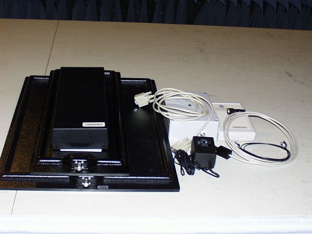
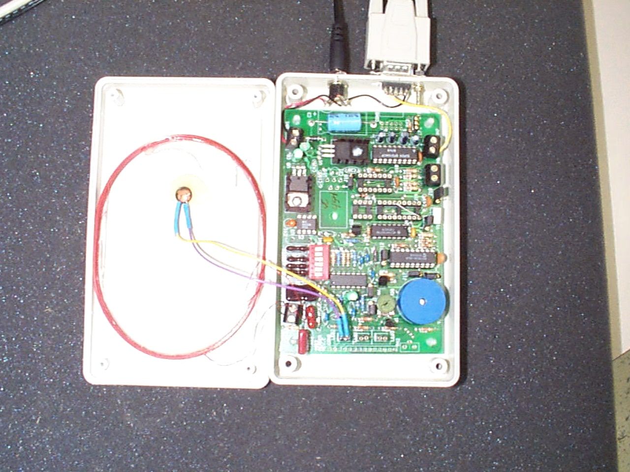
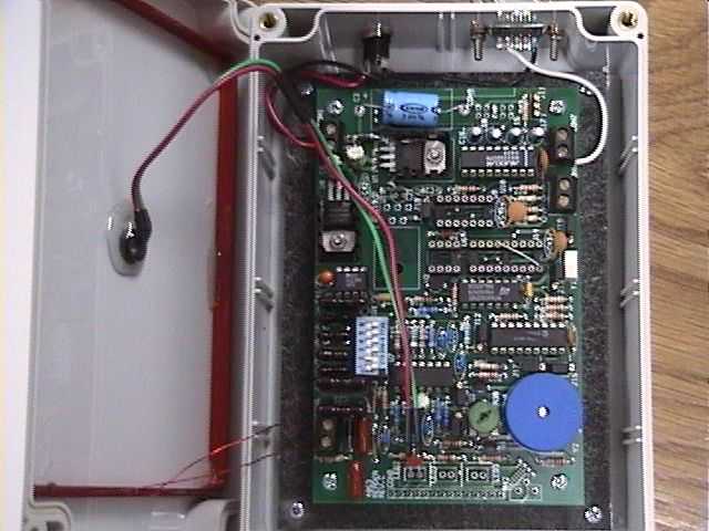
MICRON COMMUNICATIONS, INC. 3176 South Denver Way; Boise, Idaho 83707-0006 MicroBadge 4053 Users Manual Users Manual MicroBadge 4053 NOTE: - This equipment has been tested and found to comply with the limits for a Class A digital device, pursuant to Part 15 of the FCC Rules. These limits are designed to provide reasonable protection against harmful interference when the equipment is operated in a commercial environment. This equipment generates, uses, and can radiate radio frequency energy and, if not installed and used in accordance with the instruction manual, may cause harmful interference to radio communications. Operation of the equipment in a residential area is likely to cause harmful interference in which case the user will be required to correct the interference at his own expense. MICROBADGE 4053 USERS MANUAL 1 11 1 Table of Content SECTION 1 MicroBadge 4053 Reader Description1 SECTION 2 Installation Instructions2 SECTION 3 Operating Limitations3 SECTION 4 Maintenance4 MicroBadge 4053 Reader Description The MicroBadge 4053 RFID reader is a self-contained low frequency reader for powering and interrogating passive RFID transponders. The reader is configured to interface with other electronic devices via an RS-232 or RS-485 connection. The 4053 reader emits a low frequency magnetic field, which will provide enough energy to power a transponder within the read range of the transponder. The transponder will send a unique identification, which the reader detects. If the identification code is valid and the internal error detection determines that there are no errors in the data received, an audible tone is emitted, the red LED on the front of the reader turns to green, and the code is sent to the RS232 or RS484 port of the reader. SectionSection 1 3 33 3 Installation Instructions The reader should be mounted near the location that is desired to be monitored. Before final installation of the reader, test the system with tags at range and orientation typical of system operation. Typically, the read range for a credit card size transponder is approximately 8 inches, and an 18mm button transponder has a read range of 5 inches. Caution should be taken that the reader is not mounted within 12 inches of metallic objects, because of possible performance degradation of the system. Once a suitable location is determined, position the reader to allow the transponder to be presented nearly parallel to the face of the reader. This allows for the greatest read range for the entire system. After the reader is mounted, the 12 VDC (nominally) power transformer should be plugged into a 110 volt, 50 – 60 Hz socket, and the power plug from transformer should be plugged into the reader power jack. The LED indicator on the front of the reader should be glowing with a RED color. Next, plug an RS232 cable with a nine–pin connector into the RS232 port of the reader, and connect the other end of the cable into the serial port of a computer. To test the functionality of the reader, start up a terminal program in the computer. (PROCOM or Windows terminal program will work fine.) Set the communications parameters to 19,2000 baud, no parity, eight data bits, and one stop bit. Make certain that the port selected in the terminal port corresponds to the port that the RS232 cable is connected. Next, present a transponder to the reader at approximately 4 inches and parallel to the face of the reader. An audible “beep” should be heard, and the LED should alternately flash RED and GREEN. Moreover, you should see a string of 18 digits displayed on the computer monitor. These digits correspond to the identification code stored in the transponder. If an audible “beep” is head, but the computer does not display the 18 digits on the monitor, verify that the proper port is selected, and that the proper communications parameters are set. Section 2 4 44 4 If an audible “beep” is not heard, verify that the LED is glowing RED, which indicates that power is being supplied to the reader. Try another transponder, and bring it closer to the reader antenna. If this fails to produce a sound, disconnect the unit from the computer and from power and call the factory. 5 55 5 Operating Limitations Storage Temperature-5590Degrees C Operating Temperature-4070Degrees C Operating Frequency123127 KHz Read Range 050cm Power Consumption1.5Watts Power Supply Voltage9.015.0 VDC Section 3 6 66 6 Maintenance There are no user repairable components within the reader, and any maintenance performed on the reader should be performed only by factory trained personnel. Section 4
Users Manual
MICRON COMMUNICATIONS, INC. 3176 South Denver Way; Boise, Idaho 83707-0006 MicroBadge 4053 Users Manual Users Manual MicroBadge 4053 NOTE: This equipment has been tested and found to comply with the limits for a Class B digital device, pursuant to Part 15 of the FCC Rules. These limits are designed to provide reasonable protection against harmful interference in a commercial or residential installation. This equipment generates, uses and can radiate radio frequency energy and, if not installed and used in accordance with the instructions, may cause harmful interference to radio communications. However, there is no guarantee that interference will not occur in a particular installation. If this equipment does cause harmful interference to radio or television reception, which can be determined by turning the equipment off and on, the user is encouraged to try to correct the interference by one or more of the following measures: - Reorient or relocate the receiving antenna. - Increase the separation between the equipment and receiver. - Connect the equipment into an outlet on a circuit different from that to which the receiver is connected. - Consult the dealer or an experienced radio/TV technician for help. MICROBADGE 4053 USERS MANUAL 11 Table of Content SECTION 1 MicroBadge 4053 Reader Description1 SECTION 2 Installation Instructions2 SECTION 3 Operating Limitations3 SECTION 4 Maintenance4 MicroBadge 4053 Reader Description The MicroBadge 4053 RFID reader is a self-contained low frequency reader for powering and interrogating passive RFID transponders. The reader is configured to interface with other electronic devices via an RS-232 or RS-485 connection. The 4053 reader emits a low frequency magnetic field, which will provide enough energy to power a transponder within the read range of the transponder. The transponder will send a unique identification, which the reader detects. If the identification code is valid and the internal error detection determines that there are no errors in the data received, an audible tone is emitted, the red LED on the front of the reader turns to green, and the code is sent to the RS232 or RS484 port of the reader. SectionSection 1 1 33 Installation Instructions The reader should be mounted near the location that is desired to be monitored. Before final installation of the reader, test the system with tags at range and orientation typical of system operation. Typically, the read range for a credit card size transponder is approximately 8 inches, and an 18mm button transponder has a read range of 5 inches. Caution should be taken that the reader is not mounted within 12 inches of metallic objects, because of possible performance degradation of the system. Once a suitable location is determined, position the reader to allow the transponder to be presented nearly parallel to the face of the reader. This allows for the greatest read range for the entire system. After the reader is mounted, the 12 VDC (nominally) power transformer should be plugged into a 110 volt, 50 – 60 Hz socket, and the power plug from transformer should be plugged into the reader power jack. The LED indicator on the front of the reader should be glowing with a RED color. Next, plug an RS232 cable with a nine–pin connector into the RS232 port of the reader, and connect the other end of the cable into the serial port of a computer. To test the functionality of the reader, start up a terminal program in the computer. (PROCOM or Windows terminal program will work fine.) Set the communications parameters to 19,2000 baud, no parity, eight data bits, and one stop bit. Make certain that the port selected in the terminal port corresponds to the port that the RS232 cable is connected. Next, present a transponder to the reader at approximately 4 inches and parallel to the face of the reader. An audible “beep” should be heard, and the LED should alternately flash RED and GREEN. Moreover, you should see a string of 18 digits displayed on the computer monitor. These digits correspond to the identification code stored in the transponder. If an audible “beep” is head, but the computer does not display the 18 digits on the monitor, verify that the proper port is selected, and that the proper communications parameters are set. Section 2 44 If an audible “beep” is not heard, verify that the LED is glowing RED, which indicates that power is being supplied to the reader. Try another transponder, and bring it closer to the reader antenna. If this fails to produce a sound, disconnect the unit from the computer and from power and call the factory. 55 Operating Limitations Storage Temperature-5590Degrees C Operating Temperature-4070Degrees C Operating Frequency123127KHz Read Range 050cm Power Consumption1.5Watts Power Supply Voltage9.015.0VDC Section 3 66 Maintenance There are no user repairable components within the reader, and any maintenance performed on the reader should be performed only by factory trained personnel. Section 4
Cover Letter(s)
C:\Ready_To_Convert\Doc\13603.DOC Request for Confidentiality FCC ID : LC6-4053 Federal Communications Commission Equipment Approval Services P.O. Box 358315 Pittsburgh, PA 15251-5315 Micron Communications, Inc. requests that all information including circuit description and block diagrams within this application, except information that must be publicly available, be withheld from public inspection. The information contained within this application is confidential to Micron Communications, Inc. and took considerable time, effort, and expertise to develop. If the information were available to other potential competing companies, they could forgo most of the development time and expense, providing them with a potentially damaging and unfair competitive advantage. Thank you, Mark Tuttle Vice President Micron Communications, Inc.
Cover Letter(s)
C:\Ready_To_Convert\Doc\13604.DOC November 13, 1998 AUTHORIZATION AGREEMENT FCC Part 15 Submission I, Mark Tuttle, appoint TUV Product Service, Inc., to act as the authorized representative in the preparation of applications for registration of equipment under Part 15 of Rules and Regulations of the Federal Communications Commission. I certify that the information provided to TUV Product Service, Inc., properly describes the device or system for which equipment authorization is requested. APPLICANT ANTI-DRUG ABUSE CERTIFICATION The applicant certifies that, in the case of an individual applicant, he or she is not subject to a denial of federal benefits, that includes FCC benefits, pursuant to section 5301 of the Anti-Drug Abuse Act of 1988, 21 U.S.C. 853 (a), or, in the case of a non-individual applicant (e.g. corporation, partnership, or other unincorporated association) no party to the application is subject to a denial of federal benefits, that includes FCC benefits, pursuant to that section. For the definition of a “party” for these purposes see 47 CFR 1.2002(b). This Authorization, dated this 5 th day of November , 1998, expires on the 1st day of May, 1998. By Mark Tuttle SignaturePrinted TitleVice President ApplicantMicron Communications, Inc. (Must agree with section I on FCC Form 731 - Applicant’s Full Business Name) 3176 South Denver Way Address Boise, Idaho 83707 City, State, Zip
Cover Letter(s)
FCC ID: LC6-4053 ENGINEERING STATEMENT For Certification of Micron Communications, Inc. Industrial Reader FCC ID: LC6-4053 Model No. 4053 I am an Electromagnetic Compatibility test engineer with TUV Product Service, Boulder, Colorado. My education and experience are a matter of record with the Federal Communications Commission. TUV Product Service Corporation has been authorized by Micron Communications, Inc. , 3176 South Denver Way, Boise, Idaho 83707-006, to make FCC Part 15 Certification measurements on the Industrial Reader. These tests were made by me or under my supervision at our Pinewood Springs Laboratory which is registered with the FCC under Paragraph 15 of the FCC Rules. Test data required by the FCC for FCC Part 15 Certification is included in this report. It is submitted that the above equipment meets FCC requirements and FCC Part 15 Certification is hereby requested. ________________________ Shawn Singh Engineer TUV Product Service Dated: 18 November 1998
Cover Letter(s)
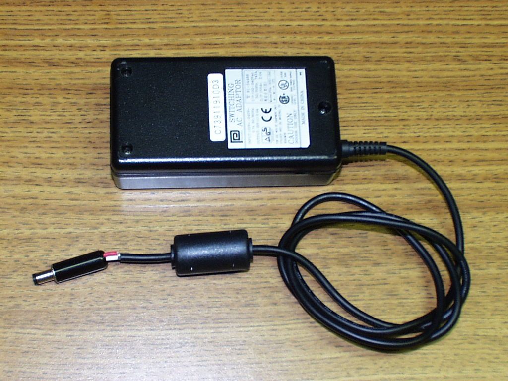
January 05, 1999 FCC Laboratory 7435 Oakland Mills Road Columbia, MD 21046 Re. FCC ID: LC6-4053, Form 731 Confirmation Number EA92367 Dear Certification Officer, TUV Product Service submitted a 15.209 electronic application on behalf of Micron Communications, Inc. on 11/18/98. The equipment passed FCC Class A emissions testing, however, per 15.207 requirements the equipment did not pass Class B requirements for conducted emissions. The equipment was retested with a new power supply and passed FCC Class B conducted emissions as well as radiated emissions with a Phihong PSA-30U-150 AC adapter with a shielded power cord. They will market their equipment with Phihong AC adapter in place of Condor D7-10-01 transformer which was originally tested. A ferrite manufactured by Fair-rite, part# 0443164251, was also removed from the 7.5 ft antenna cable on the tag reader side. We are submitting a new test report and revised user manual and photos which reflect the retested data. Please feel free to contact me for any additional information. Sincerely, Shawn Singh EMC Engineer TUV Product Service
Test Report
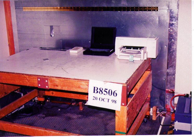
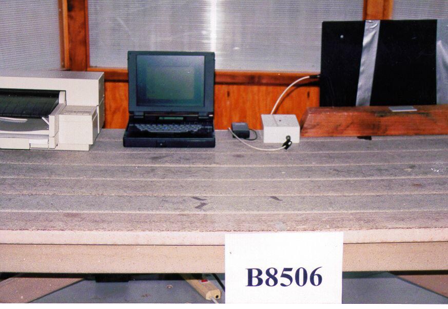
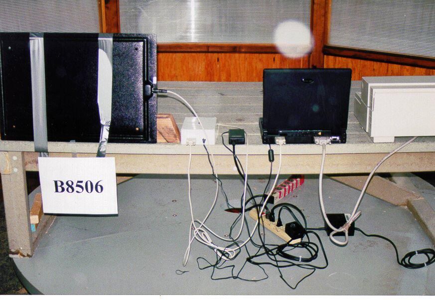
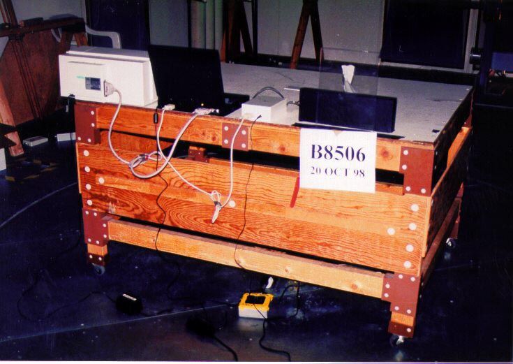
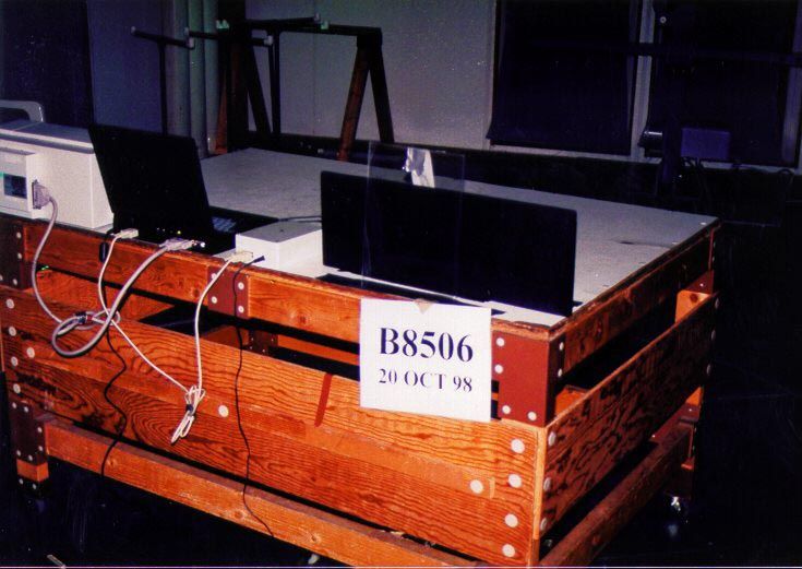
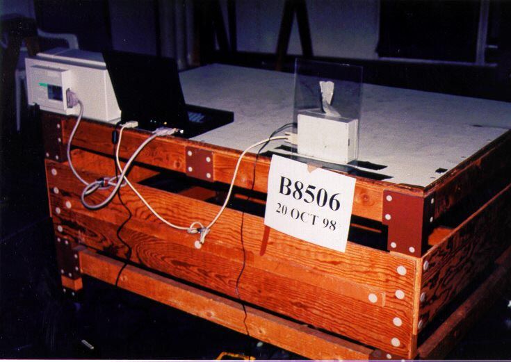
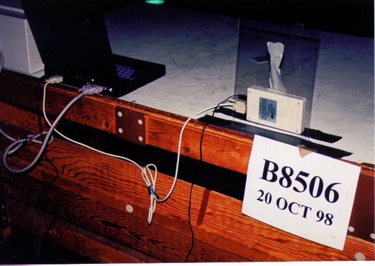
FCC ID: LC6-4053 File No. B201850601, Page 1 of 5 TÜV PRODUCT SERVICE INC40 Meadow RoadPinewood Springs, Lyons, CO 80540 Tel: 303 786 7999 Fax: 303 449 3004Rev.No 1.0 EMC EMISSION - TEST REPORT Test Report No. B850601 Issue Date18 November 1998 Model / Serial No. 4053 / EMC-1 Product TypeIndustrial Reader ClientMicron Communications, Inc. ManufacturerMicron Communications, Inc. License holderMicron Communications, Inc. Address3176 South Denver Way Boise, Idaho 83707-0006 Test Criteria AppliedFCC Part 1515.209C Test Start Date:20 October 1998 Test End Date:02 November 1998 Test Result ! !! ! PASS " "" " FAIL Test Report Project No. B201850601 Total Pages including Appendices 59 Reviewed By : Felix J. ChavezReviewed By : Shawn Singh TÜV Product Service Inc is a subcontractor to TÜV Product Service, GmbH according to the principles outlined in ISO/IEC Guide 25 and EN 45001. TÜV Product Service Inc reports apply only to the specific samples tested under stated test conditions. It is the manufacturer's responsibility to assure that additional production units of this model are manufactured with identical electrical and mechanical components. TÜV Product Service Inc shall have no liability for any deductions, inferences or generalizations drawn by the client or others from TÜV Product Service Inc issued reports. This report is the confidential property of the client. As a mutual protection to our clients, the public and ourselves, extracts from the test report shall not be reproduced except in full without our written approval of TÜV Product Service. This report shall not be used by the client to claim product endorsement by NVLAP or any agency of the US government. TÜV Product Service Inc and its professional staff hold government and professional organization certifications and are members of AAMI, ACIL, AEA, ANSI, IEEE, NVLAP, and VCCI FCC ID: LC6-4053 File No. B201850601, Page 2 of 5 TÜV PRODUCT SERVICE INC40 Meadow RoadPinewood Springs, Lyons, CO 80540 Tel: 303 786 7999 Fax: 303 449 3004Rev.No 1.0 DIRECTORY - EMISSIONS DocumentationPage(s) Test report1 - 3 Directory2 Test Regulations3 General Remarks3 Test Equipment Used4-5 Appendix A Transmitter Data SheetsA1 - A6 Appendix B Detailed Test Data SheetsB1 - B27 Appendix C Test Plan and Constructional Data FormC1 - C11 Appendix D Measurement of ProtocolD1 - D3 Appendix E Test Setup PhotographsE1 - E7 STATEMENT OF MEASUREMENT UNCERTAINTY The data and results referenced in this document are true and accurate. The reader is cautioned that there may be errors within the calibration limits of the equipment and facilities that can account for a nominal measurement error of ±4 dB. Furthermore, component and process variability of devices similar to that tested may result in additional deviation. The manufacturer has the sole responsibility of continued compliance of the device. FCC ID: LC6-4053 File No. B201850601, Page 3 of 5 TÜV PRODUCT SERVICE INC40 Meadow RoadPinewood Springs, Lyons, CO 80540 Tel: 303 786 7999 Fax: 303 449 3004Rev.No 1.0 EMISSIONS TEST REGULATIONS : The tests were performed according to following regulations : ! - Federal Communication Commission part 15 ! - Class A " - Class B ! - Federal Communication Commission part 15, Subpart C ! - 15.207 ! - 15.209 -------------------------------------------------------------------------------- All tests performed according to ANSI C63.4. Emission Test Results: Conducted emissions 150 kHz - 30 MHz Test Result ! !! ! - PASS " "" " - FAIL " "" " - Not Applicable Passing Margin7 dBat11.1 MHz Failing MargindBatMHz Remarks: Radiated emissions (electric field) 30 MHz - 1000 MHz (Unintentional Radiator) Test Result ! !! ! - PASS " "" " - FAIL " "" " - Not Applicable Passing Margin4.7 dBat67.6 MHz Failing MargindBatMHz Remarks: Radiated emissions (Magnetic field) 0.125 MHz - 1.250 MHz (Intentional Radiator) Test Result ! !! ! - PASS " "" " - FAIL " "" " - Not Applicable Passing Margin23.2 dBat0.125 MHz Failing MargindBatMHz Remarks: GENERAL REMARKS: Modifications required to pass: Added a Fair-rite ferrite part #0443164251 to 7.5 ft. antenna cable on tag reader side. Test Specification Deviations: Additions to or Exclusions from: None FCC ID: LC6-4053 File No. B201850601, Page 4 of 5 TÜV PRODUCT SERVICE INC40 Meadow RoadPinewood Springs, Lyons, CO 80540 Tel: 303 786 7999 Fax: 303 449 3004Rev.No 1.0 Test Equipment Used FCC ID: LC6-4053 File No. B201850601, Page 5 of 5 TÜV PRODUCT SERVICE INC40 Meadow RoadPinewood Springs, Lyons, CO 80540 Tel: 303 786 7999 Fax: 303 449 3004Rev.No 1.0 Colorado Test Equipment 05-Nov-98 Report: B8506Date: 20 Oct.98-02 Nov.98Signature: Shawn Singh Temp: 21° CRel. Humd.: 37%Atmo. Pressure: 80kPa LocationTests ManufacturerModel NumberSerial NumberDescriptionCal DateCal Due PWREMCO3104C9203-4508Biconical antenna19-Jun-9819-Jun-99 PW-3, REMCO31469203-3376Log Periodic Antenna18-Jun-9818-Jun-99 PWCEMCO3825/29202-1945LISN15-Jul-9815-Jul-99 PWREMCO46109205-1199Royce field site source PWREMCO65029205-2738Magnetic loop30-Oct-9729-Oct-00 PWGishard600-1040 mb002Altimeter PWCHewlett Packard11947A3107A01975Transient Limiter17-Jun-9817-Jun-99 PWRHewlett Packard85650A2043A00256Quasi Peak Adapter (set 1)17-Jun-9817-Jun-99 PWRHewlett Packard85650A2811A01300Quasi Peak Adapter18-Nov-9718-Nov-98 PWR, CHewlett Packard85662A2112A02220Display Section11-Mar-9811-Mar-99 PWR, C,Hewlett Packard85662A2403A08749Display Section01-Apr-9801-Apr-99 PWR, CHewlett Packard8566B2115A00853Spectrum Analyzer (dc-22 GHz)11-Mar-9811-Mar-99 PWR, CHewlett Packard8566B2410A00154Spectrum Analyzer (dc-22 GHz)01-Apr-9801-Apr-99 PWRMini-CircuitsZHL-1042JD020698-14RF Pre-Amplifier (10-4200 MHZ)13-Feb-9813-Feb-99 PWCPolarad ElectroniESH3-Z2357.881J.32Transient Limiter PWRadio Shack63-867005Temperature / Humidity Indicator PWCRhode & SchwarzESH2-Z5830364/002LISN 50 ohm/50uH 3 line23-Feb-9823-Feb-99 PWCRhode & SchwarzESH3872318/036Low Frequency Receiver03-Sep-9803-Sep-99 FCC ID: LC6-4053 File No. B201850601, Page A1 of A6…
Text truncated - open the document above for the full version.
Test Report
FCC ID: LC6-4053 File No. B201850601, Page 1 of 5 TÜV PRODUCT SERVICE INC40 Meadow RoadPinewood Springs, Lyons, CO 80540Tel: 303 786 7999Fax: 303 449 3004Rev.No 1.0 EMC EMISSION - TEST REPORT Test Report No. B850601a Issue Date06 January 1999 Model / Serial No. 4053 / EMC-1 Product TypeIndustrial Reader ClientMicron Communications, Inc. ManufacturerMicron Communications, Inc. License holderMicron Communications, Inc. Address3176 South Denver Way Boise, Idaho 83707-0006 Test Criteria AppliedFCC Part 1515.209C Test Start Date:20 October 1998 Test End Date:30 December 1998 Test Result nn PASSoo FAIL Test Report Project No. B201850601 Total Pages including Appendices 67 Reviewed By : Felix J. ChavezReviewed By : Shawn Singh TÜV Product Service Inc is a subcontractor to TÜV Product Service, GmbH according to the principles outlined in ISO/IEC Guide 25 and EN 45001. TÜV Product Service Inc reports apply only to the specific samples tested under stated test conditions. It is the manufacturer's responsibility to assure that additional production units of this model are manufactured with identical electrical and mechanical components. TÜV Product Service Inc shall have no liability for any deductions, inferences or generalizations drawn by the client or others from TÜV Product Service Inc issued reports. This report is the confidential property of the client. As a mutual protection to our clients, the public and ourselves, extracts from the test report shall not be reproduced except in full without our written approval of TÜV Product Service. This report shall not be used by the client to claim product endorsement by NVLAP or any agency of the US government. TÜV Product Service Inc and its professional staff hold government and professional organization certifications and are members of AAMI, ACIL, AEA, ANSI, IEEE, NVLAP, and VCCI FCC ID: LC6-4053 File No. B201850601, Page 2 of 5 TÜV PRODUCT SERVICE INC40 Meadow RoadPinewood Springs, Lyons, CO 80540Tel: 303 786 7999Fax: 303 449 3004Rev.No 1.0 DIRECTORY - EMISSIONS DocumentationPage(s) Test report1 - 3 Directory2 Test Regulations3 General Remarks3 Test Equipment Used4-5 Appendix A Transmitter Data SheetsA1 - A6 Appendix B Detailed Test Data SheetsB1 - B38 Appendix C Test Plan and Constructional Data FormC1 - C11 Appendix D Measurement of ProtocolD1 - D3 Appendix E Test Setup PhotographsE1 - E4 STATEMENT OF MEASUREMENT UNCERTAINTY The data and results referenced in this document are true and accurate. The reader is cautioned that there may be errors within the calibration limits of the equipment and facilities that can account for a nominal measurement error of ±4 dB. Furthermore, component and process variability of devices similar to that tested may result in additional deviation. The manufacturer has the sole responsibility of continued compliance of the device. FCC ID: LC6-4053 File No. B201850601, Page 3 of 5 TÜV PRODUCT SERVICE INC40 Meadow RoadPinewood Springs, Lyons, CO 80540Tel: 303 786 7999Fax: 303 449 3004Rev.No 1.0 EMISSIONS TEST REGULATIONS : The tests were performed according to following regulations : n - Federal Communication Commission part 15o - Class An - Class B n - Federal Communication Commission part 15, Subpart Cn - 15.207n - 15.209 -------------------------------------------------------------------------------- All tests performed according to ANSI C63.4. Emission Test Results: Conducted emissions 150 kHz - 30 MHz Test Resultnn - PASS oo - FAILoo - Not Applicable Passing Margin2dBat1.6MHz Failing MargindBatMHz Remarks:Worst case emissions were found with 7.5’ cable. Radiated emissions (electric field) 30 MHz - 1000 MHz (Unintentional Radiator) Test Resultnn - PASS oo - FAILoo - Not Applicable Passing Margin3.5dBat266.1MHz Failing MargindBatMHz Remarks: Radiated emissions (Magnetic field) 0.125 MHz - 1.250 MHz (Intentional Radiator) Test Resultnn - PASS oo - FAILoo - Not Applicable Passing Margin23.2dBat0.125MHz Failing MargindBatMHz Remarks:No higher emissions were found with Phihong PSA-30U-150 AC Adapter. No significant difference was found between 3’ and 7.5’ antenna cables. GENERAL REMARKS: Modifications required to pass: None Test Specification Deviations: Additions to or Exclusions from: None FCC ID: LC6-4053 File No. B201850601, Page 4 of 5 TÜV PRODUCT SERVICE INC40 Meadow RoadPinewood Springs, Lyons, CO 80540Tel: 303 786 7999Fax: 303 449 3004Rev.No 1.0 Test Equipment Used FCC ID: LC6-4053 File No. B201850601, Page 5 of 5 TÜV PRODUCT SERVICE INC40 Meadow RoadPinewood Springs, Lyons, CO 80540Tel: 303 786 7999Fax: 303 449 3004Rev.No 1.0 Colorado Test Equipment 05-Nov-98 Report: B8506Date: 20 Oct.98-21 Dec.98Signature: Shawn Singh Temp: 21° CRel. Humd.: 37%Atmo. Pressure: 80kPa LocationTests ManufacturerModel NumberSerial NumberDescriptionCal DateCal Due PWREMCOSAS-200/512104Log Periodic Antenna13-Jul-9813-Jul-99 PWREMCO31087059203-2457Biconical Dipole Antenna06-Jul-9806-Jul-99 PW-3, REMCO31469203-3376Log Periodic Antenna18-Jun-9818-Jun-99 PWCEMCO3825/29202-1945LISN15-Jul-9815-Jul-99 PWREMCO46109205-1199Royce field site source PWREMCO65029205-2738Magnetic loop30-Oct-9729-Oct-00 PWGishard600-1040 mb002Altimeter PWCHewlett Packard11947A3107A01975Transient Limiter17-Jun-9817-Jun-99 PWRHewlett Packard85650A2043A00256Quasi Peak Adapter (set 1)17-Jun-9817-Jun-99 PWRHewlett Packard85650A2811A01300Quasi Peak Adapter18-Nov-9718-Nov-98 PWR, CHewlett Packard85662A2112A02220Display Section11-Mar-9811-Mar-99 PWR, C,Hewlett Packard85662A2403A08749Display Section01-Apr-9801-Apr-99 PWR, CHewlett Packard8566B2115A00853Spectrum Analyzer (dc-22 GHz)11-Mar-9811-Mar-99 PWR, CHewlett Packard8566B2410A00154Spectrum Analyzer (dc-22 GHz)01-Apr-9801-Apr-99 PWRMini-CircuitsZHL-1042JD020698-14RF Pre-Amplifier (10-4200 MHZ)13-Feb-9813-Feb-99 PWCPolarad ElectroniESH3-Z2357.881J.32Transient Limiter PWRadio Shack63-867005Temperature / Humidity Indicator PWCRhode & SchwarzESH2-Z5830364/002LISN 50 ohm/50uH 3 line23-Feb-9823-Feb-99 PWCRhode & SchwarzESH3…
Text truncated - open the document above for the full version.
Contact Information
Applicant
Mark Tuttle(Vice President)
Technical Contact
TUV Product ServiceShawn Singh
[email protected]303 402 5262
5541 Central Avenue · Boulder, Colorado · United States
Non-Technical Contact
TUV Product ServiceFelix J Chavez
[email protected]303 402 5248
Test Firm
International Approval Laboratories, LLCTodd Seeley
Technical Specifications
| # | Rule Parts | Frequency Range | Power Output | Tolerance |
|---|---|---|---|---|
| 1 | 15C | 0.123 MHz - 0.127 MHz | - | % |
Other Applications from Micron Communications Inc

LC6-MB-I-WM
Mar 29, 1999DCD - Part 15 Low Power Transmitter Below 1705 kHz
Equipment Class
DCD - Part 15 Low Power Transmitter Below 1705 kHz
LC6-MB-I-M
Mar 29, 1999DSR - Part 15 Remote Control/Security Device Transceiver
Equipment Class
DSR - Part 15 Remote Control/Security Device TransceiverLC6-4120
Jun 15, 1998Tag Reader
Equipment Class
DSS - Part 15 Spread Spectrum TransmitterLC65269W
Apr 22, 1997Tag Reader Transmitter w/parallel port Max Output Power 900 milliwatts
Equipment Class
DSS - Part 15 Spread Spectrum Transmitter