LEPXMT03R/C for Lights on Repair/Service Vehicle
Dakota Digital Inc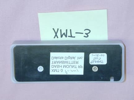
Click to zoom
Application Details
- Equipment Class
- DSC - Part 15 Security/Remote Control Transmitter
- Date of Grant
- May 22, 2000
- Application Purpose
- Original Equipment
- Date of Application
- Jan 31, 2000
- Equipment Note
- R/C for Lights on Repair/Service Vehicle
- Frequency Range
- 301.00000000 - 301.00000000
- Company
- Dakota Digital Inc
- Country
- United States
Documents & Files
Document Text
Text extracted from the exhibit documents filed with the FCC. Open a document above to read the original.
Users Manual
XMT-3 USER’S GUIDE This transmitter is activated by pressing one of the four push button switches. Each button activates a different channel. When a button is pressed the red light will come on indicating that it is operating. If the red light does not come on or comes on very dimly, the battery may need to be replaced. To replace the battery: 1. Remove the two screws located on the back of the transmitter. 2. Remove the cover from the back. 3. Remove the old battery and replace with a new GP23A type battery. 4. Install the cover on the back. 5. Tighten the two screws on the back. Do not over-tighten them as the threads may strip out. MODIFICATIONS Changes or modifications to this unit could void the user’s authority to operate the equipment. This device complies with part 15 of FCC rules. Operation is subject to the following two conditions: (1) This device may not cause harmful interference, and (2) This device must accept any interference received, including interference that may cause undesired operation.
External Photos
Photo 1 - Top/Front External View Photo 2 - Bottom/Rear Exterior View Photo 3 - PWB Top Photo 4 - PWB Bottom Photo 5 - Inside of Top Cover
ID Label/Location Info
Device Label This label will be placed on the center, back of the transmitter, located between the two back-plate screws. 0.5” 1.75” FCC ID. LEPXMT03 This device complies with Part 15 of the FCC Rules.
Operational Description
Circuit Operation Description: The four push button switches turn on power to the circuit as well as indicate which function is to be transmitted to the encoder. The 12 DIP switches provide the serial number encoding for the unit. The encoder reads the four push button switches and the 12 DIP switches and converts this into a 1kHz On-Off-Keyed serial data steam to the transmitter circuit. The transmitter sends a 301MHz RF signal that is activated by the serial data stream from the encoder. 12 DIP switches HT-6014 encoder IC 301MHz RF transmitter 4 push button switches Power supply regulator
Schematics
1 2 34 A BC D 4 3 2 1 D CB A Title Number Revision Size A Date: 1-Feb-2000 Sheet of File: C:\Program Files\Design Explorer 99\dakdig\XMT-DASH.ddb Drawn By: A0 1 A1 2 A2 3 A3 4 A4 5 A5 6 A6 7 A7 8 D8 10 D9 11 D10 12 D11 13 LED 14 OSC1 15 OSC2 16 DOUT 17 U1HT6014 Vin 1 GND 2 +5V 3 U2JRC78L02 C1CAP-.01U + C2.33u tant SW1SW-PBSW2SW-PBSW3SW-PBSW4SW-PB D2LED R21.5M VCC VCC 123 TX99CON3 + C347u 16V D11N914BD31N914BD41N914BD51N914B D71N914BD81N914BD91N914BD101N914B C4100pF L1FERRITE BEADL2FERRITE BEAD 123456 121110 987 S1SW DIP-6 123456 121110 987 S2SW DIP-6 VCC GP23BATTERY
Test Report
KTL Test Report:9L0447RUS Applicant:Dakota Digital 3421 Hovland Drive Sioux Falls, South Dakota 57107 Equipment Under Test:XMT-3 (E.U.T.) FCC ID:LEPXMT03 In Accordance With:FCC Part 15, Subpart C For Low Power Transmitters Operating Periodically In The Band 40.66 - 40.77 MHz And Above 70 MHz Tested By:KTL Dallas Inc. 802 North Kealy Lewisville, Texas 75057 Authorized By: Tom Tidwell, RF Manager Date:January 27, 2000 Total Number of Pages:35 KTL Dallas, Inc.FCC PART 15, SUBPART C FOR LOW POWER TRANSMITTERS PROJECT NO.: 9L0447RUS EQUIPMENT: XMT-3 FCC ID: LEPXMT03 Page 2 of 35 Table of Contents Section 1. Summary of Test Results ........................................................................................... 3 Section 2. Equipment Under Test (E.U.T.) ................................................................................. 5 Section 3. Equipment Configuration ........................................................................................... 8 Section 4. Transmission Requirements ..................................................................................... 13 Section 5. Radiated Emissions ..................................................................................................18 Section 6. Occupied Bandwidth ................................................................................................ 23 Section 7. Frequency Tolerance Devices in the Frequency Band 40.66 - 40.77 MHz.......... 26 Section 8. Periodic Alternate Field Strength Requirements...................................................... 27 Section 9. Powerline Conducted Emissions .............................................................................. 28 Section 10. Block Diagrams ........................................................................................................ 31 Section 11. Test Equipment List .................................................................................................32 ANNEX A – ADDITIONAL INFORMATION............................................................................ 34 KTL Dallas, Inc.FCC PART 15, SUBPART C FOR LOW POWER TRANSMITTERS PROJECT NO.: 9L0447RUS EQUIPMENT: XMT-3 FCC ID: LEPXMT03 Page 3 of 35 Section 1.Summary of Test Results Manufacturer:Dakota Digital Model No.:XMT-3 Serial No.:None General:All measurements are traceable to national standards. These tests were conducted on a sample of the equipment for the purpose of demonstrating compliance with Part 15, Subpart C, Paragraph 15.231. All tests were conducted using measurement procedure ANSI C63.4-1992. Radiated emissions are made on an open area test site. A description of the test facility is on file with the FCC. New SubmissionProduction Unit Class II Permissive ChangePre-Production Unit THIS TEST REPORT RELATES ONLY TO THE ITEM(S) TESTED. THE FOLLOWING DEVIATIONS FROM, ADDITIONS TO, OR EXCLUSIONS FROM THE TEST SPECIFICATIONS HAVE BEEN MADE. See “ Summary of Test Data”. NVLAP LAB CODE: 100351-0 TESTED BY: David Light DATE: 1/19/00 – 1/25/00 KTL Dallas, Inc. authorizes the above named company to reproduce this report provided it is reproduced in its entirety and for use by the company’s employees only. Any use which a third party makes of this report, or any reliance on or decisions to be made based on it, are the responsibility of such third parties. KTL Dallas, Inc. accepts no responsibility for damages, if any, suffered by any third party as a result of decisions made or actions based on this report. This report applies only to the items tested. KTL Dallas, Inc.FCC PART 15, SUBPART C FOR LOW POWER TRANSMITTERS PROJECT NO.: 9L0447RUS EQUIPMENT: XMT-3 FCC ID: LEPXMT03 Page 4 of 35 Summary Of Test Data Name of TestParagraph NumberResults Transmission Requirements15.231(a)Complies Radiated Emissions15.231(b)Complies Occupied Bandwidth15.231(c)Complies Frequency Tolerance15.231(d)Complies Periodic Alternate Field Strength Requirements15.231(e)N/A Powerline Conducted Emissions15.207N/A Footnotes:(1) Powerline Conducted Emissions is not applicable since the E.U.T. is battery operated. Test Conditions: IndoorTemperature: ____22____°C Humidity:____45 ____% OutdoorTemperature: ____18____°C Humidity:____50____% KTL Dallas, Inc.FCC PART 15, SUBPART C FOR LOW POWER TRANSMITTERS PROJECT NO.: 9L0447RUS EQUIPMENT: XMT-3 FCC ID: LEPXMT03 Page 5 of 35 Section 2.Equipment Under Test (E.U.T.) General Equipment Information Frequency Range: 301.5 MHz Operating Frequency(ies) of Sample: 301.5 MHz Emission Designator: 15K0L1D Supply Power Requirement: 12 Vdc Battery Duty Cycle Calculation: 20 log (52.2ms/100ms) = -5.63 dB 52.3 ms total on time during 100 ms KTL Dallas, Inc.FCC PART 15, SUBPART C FOR LOW POWER TRANSMITTERS PROJECT NO.: 9L0447RUS EQUIPMENT: XMT-3 FCC ID: LEPXMT03 Page 6 of 35 Description of E.U.T. The E.U.T. is a 300 MHz RF transmitter use to control auxiliary lights on tire repair/service vehicle. Modifications Incorporated in E.U.T. The EUT has not been modified from what is described by the brand name and unique type identification stated above. KTL Dallas, Inc.FCC PART 15, SUBPART C FOR LOW POWER TRANSMITTERS PROJECT NO.: 9L0447RUS EQUIPMENT: XMT-3 FCC ID: LEPXMT03 Page 7 of 35 Justification The E.U.T. was configured for testing as per typical installation. The following combinations were investigated to establish worst case configuration: (1) Continuous transmission. Exercise Program The E.U.T. exercise program used during radiated and conducted testing was designed to exercise the various system components in a manner similar to typical use. Exercise mode: (1) Continuous transmission KTL Dallas, Inc.FCC PART 15, SUBPART C FOR LOW POWER TRANSMITTERS PROJECT NO.: 9L0447RUS EQUIPMENT: XMT-3 FCC ID: LEPXMT03 Page 8 of 35 Section 3.Equipment Configuration Equipment Configuration List: ItemDescriptionModel No.Serial.Rev. (A)TransmitterXMT-3None (B) (C) (D) (E) (F) (G) Inter-connection Cables: NONE ItemDescriptionLength (m) (1) (2) (3) (4) (5) (6) (7) (8) KTL…
Text truncated - open the document above for the full version.
Test Report
KTL Test Report:9L0447RUS Applicant:Dakota Digital 3421 Hovland Drive Sioux Falls, South Dakota 57107 Equipment Under Test:XMT-3 (E.U.T.) FCC ID:LEPXMT03 In Accordance With:FCC Part 15, Subpart C For Low Power Transmitters Operating Periodically In The Band 40.66 - 40.77 MHz And Above 70 MHz Tested By:KTL Dallas Inc. 802 North Kealy Lewisville, Texas 75057 Authorized By: Tom Tidwell, RF Manager Date:January 27, 2000 Total Number of Pages:35 KTL Dallas, Inc.FCC PART 15, SUBPART C FOR LOW POWER TRANSMITTERS PROJECT NO.: 9L0447RUS EQUIPMENT: XMT-3 FCC ID: LEPXMT03 Page 2 of 35 Table of Contents Section 1. Summary of Test Results........................................................................................3 Section 2. Equipment Under Test (E.U.T.)..............................................................................5 Section 3. Equipment Configuration........................................................................................8 Section 4. Transmission Requirements...................................................................................13 Section 5. Radiated Emissions...............................................................................................18 Section 6. Occupied Bandwidth.............................................................................................23 Section 7. Frequency Tolerance Devices in the Frequency Band 40.66 - 40.77 MHz..........26 Section 8. Periodic Alternate Field Strength Requirements.....................................................27 Section 9. Powerline Conducted Emissions............................................................................28 Section 10. Block Diagrams....................................................................................................31 Section 11. Test Equipment List..............................................................................................32 ANNEX A – ADDITIONAL INFORMATION.........................................................................34 KTL Dallas, Inc.FCC PART 15, SUBPART C FOR LOW POWER TRANSMITTERS PROJECT NO.: 9L0447RUS EQUIPMENT: XMT-3 FCC ID: LEPXMT03 Page 3 of 35 Section 1.Summary of Test Results Manufacturer:Dakota Digital Model No.:XMT-3 Serial No.:None General:All measurements are traceable to national standards. These tests were conducted on a sample of the equipment for the purpose of demonstrating compliance with Part 15, Subpart C, Paragraph 15.231. All tests were conducted using measurement procedure ANSI C63.4-1992. Radiated emissions are made on an open area test site. A description of the test facility is on file with the FCC. New SubmissionProduction Unit Class II Permissive ChangePre-Production Unit THIS TEST REPORT RELATES ONLY TO THE ITEM(S) TESTED. THE FOLLOWING DEVIATIONS FROM, ADDITIONS TO, OR EXCLUSIONS FROM THE TEST SPECIFICATIONS HAVE BEEN MADE. See “ Summary of Test Data”. NVLAP LAB CODE: 100351-0 TESTED BY: David Light DATE: 1/19/00 – 1/25/00 KTL Dallas, Inc. authorizes the above named company to reproduce this report provided it is reproduced in its entirety and for use by the company’s employees only. Any use which a third party makes of this report, or any reliance on or decisions to be made based on it, are the responsibility of such third parties. KTL Dallas, Inc. accepts no responsibility for damages, if any, suffered by any third party as a result of decisions made or actions based on this report. This report applies only to the items tested. KTL Dallas, Inc.FCC PART 15, SUBPART C FOR LOW POWER TRANSMITTERS PROJECT NO.: 9L0447RUS EQUIPMENT: XMT-3 FCC ID: LEPXMT03 Page 4 of 35 Summary Of Test Data Name of TestParagraph NumberResults Transmission Requirements15.231(a)Complies Radiated Emissions15.231(b)Complies Occupied Bandwidth15.231(c)Complies Frequency Tolerance15.231(d)Complies Periodic Alternate Field Strength Requirements15.231(e)N/A Powerline Conducted Emissions15.207N/A Footnotes:(1) Powerline Conducted Emissions is not applicable since the E.U.T. is battery operated. Test Conditions: IndoorTemperature:____22____°C Humidity:____45 ____% OutdoorTemperature:____18____°C Humidity:____50____% KTL Dallas, Inc.FCC PART 15, SUBPART C FOR LOW POWER TRANSMITTERS PROJECT NO.: 9L0447RUS EQUIPMENT: XMT-3 FCC ID: LEPXMT03 Page 5 of 35 Section 2.Equipment Under Test (E.U.T.) General Equipment Information Frequency Range: 301.5 MHz Operating Frequency(ies) of Sample: 301.5 MHz Emission Designator: 15K0L1D Supply Power Requirement: 12 Vdc Battery Duty Cycle Calculation: 20 log (52.2ms/100ms) = -5.63 dB 52.3 ms total on time during 100 ms KTL Dallas, Inc.FCC PART 15, SUBPART C FOR LOW POWER TRANSMITTERS PROJECT NO.: 9L0447RUS EQUIPMENT: XMT-3 FCC ID: LEPXMT03 Page 6 of 35 Description of E.U.T. The E.U.T. is a 301.5 MHz RF transmitter use to control auxiliary lights on tire repair/service vehicle. Modifications Incorporated in E.U.T. The EUT has not been modified from what is described by the brand name and unique type identification stated above. KTL Dallas, Inc.FCC PART 15, SUBPART C FOR LOW POWER TRANSMITTERS PROJECT NO.: 9L0447RUS EQUIPMENT: XMT-3 FCC ID: LEPXMT03 Page 7 of 35 Justification The E.U.T. was configured for testing as per typical installation. The following combinations were investigated to establish worst case configuration: (1) Continuous transmission. Exercise Program The E.U.T. exercise program used during radiated and conducted testing was designed to exercise the various system components in a manner similar to typical use. Exercise mode: (1) Continuous transmission KTL Dallas, Inc.FCC PART 15, SUBPART C FOR LOW POWER TRANSMITTERS PROJECT NO.: 9L0447RUS EQUIPMENT: XMT-3 FCC ID: LEPXMT03 Page 8 of 35 Section 3.Equipment Configuration Equipment Configuration List: ItemDescriptionModel No.Serial.Rev. (A)TransmitterXMT-3None (B) (C) (D) (E) (F) (G) Inter-connection Cables: NONE ItemDescriptionLength (m) (1) (2) (3) (4) (5) (6) (7) (8) KTL Dallas, Inc.FCC PART 15, SUBPART C FOR LOW POWER…
Text truncated - open the document above for the full version.
Contact Information
Applicant
Ross Ortman(President)
Technical Contact
KTL Dallas, Inc.Tom Tidwell
[email protected]972-436-9600
802 N. Kealy · Lewisville, Texas · United States
Non-Technical Contact
KTL Dallas, IncTom Tidwell
[email protected]972-436-9600
Test Firm
KTL Dallas, Inc.Pat Wellborn
Technical Specifications
| # | Rule Parts | Frequency Range | Power Output |
|---|---|---|---|
| 1 | 15C | 301 MHz - 301 MHz | - |
Other Applications from Dakota Digital Inc
LEPCMD8000
Jul 19, 1994Car Alarm Receiver
Equipment Class
CRR - Superregenerative Receiver