LFFT14903Wireless Pressure Sensor Transmitter
UnderSea Sensor Systems, Inc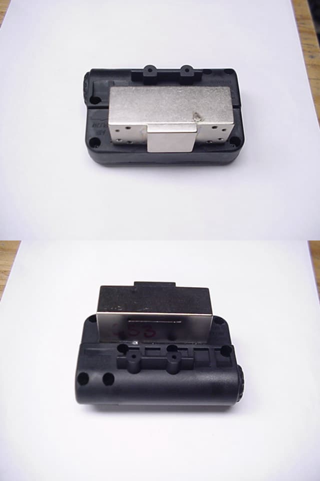
Click to zoom
Application Details
- Equipment Class
- DXX - Part 15 Low Power Communication Device Transmitter
- Date of Grant
- Feb 19, 2003
- Application Purpose
- Original Equipment
- Date of Application
- Feb 19, 2003
- Equipment Note
- Wireless Pressure Sensor Transmitter
- Frequency Range
- 0.03400000 - 0.03900000
- Company
- UnderSea Sensor Systems, Inc
- Country
- United States
Documents & Files
Document Text
Text extracted from the exhibit documents filed with the FCC. Open a document above to read the original.
Users Manual
PRISM –Wireless HUD System Installation & Operation Instructions Wireless HUD System Contents PRISM (In-Mask Receiver) -4056743 Installation of the In-Mask Receiver Remove the nose cup from inside the mask. Install the In-Mask Receiver into the mask. Tilt the In-Mask Receiver toward the speech diaphragm and locate the left side (battery side) of In-Mask Receiver ring behind speech diaphragm ring (Figure 1a). Spread right side of the In-Mask Receiver ring only far enough to get it to snap into place around speech diaphragm ring (Figure 1b). CAUTION: Do not overflex the In-Mask Receiverring legs during installation.Press top of In-Mask Receiver ring down to ensure it is fully seated (Figure 1c). Install the nose cup back into place making sure that the nose cup is fully seated behind the speech diaphragm mounting ring. (Figure 1d & 1e). WARNING : SUBSTITUTION OF COMPONENTS MAY IMPAIR INTRINSIC SAFETY. AVERTISSEMENT: LA SUBSTITUTION DE COMPOSANTS PEUT COMPROMETTRE LA SÉCURITÉ INTRINSÈQUE Intrinsically Safe. SecuriteIntrinsequeper CL. I, II, III, Div.1 Gr. A-G. Conforms to UL std. 913. Certified to CAN/CSA C22.2 No. 157-92. WARNING! To prevent ignition of a hazardous atmosphere, batteries must only be changed in an area known to be nonhazardous. AVERTISSEMENT! Afinde prevenirl’inflammation d’atmospheresdangereuses, nechanger les batteries que dansdes emplacements designesnon dangereux. This device complies with part 15 of the FCC Rules. Operation issubject to the following two conditions: (1) This device may not cause harmful interference, and (2) this device must accept any interference received, including interference that may cause undesired operation. PRISM Transducer -4056744 FIGURE 1aFIGURE 1b FIGURE 1cFIGURE 1d Battery installation In-Mask Receiver The In-Mask Receiver is powered by one CR2 lithium battery. To installthe battery, unscrew the battery cap using a coin (Figure 2a). Noting the battery polarity, install a new cell, positive ”+” end in first (Figure 2b). Screw battery cap securely into place. When a new battery is first installed, the In-Mask Receiver will blink the green low-battery indicator for 5 seconds to indicate that the battery has been installed correctly. Caution:The cell used in this device may present a fire or chemical burn hazard if mistreated. DO NOT recharge, disassemble, heat above 100 o C, or incinerate. Dispose of used cell promptly. Keep away from children. Transducer The Transducer is powered by two (2) CR2 lithium batteries. To install the batteries, unscrew the battery cap using a coin (Figure 3a).Noting the battery polarity, install twonew cells, positive ”+” end in first (Figure 3b). Both batteries MUSTbe replaced with fresh cells at the same time. Screw battery cap securely into place. Caution:The cell used in this device may present a fire or chemical burn hazard if mistreated. DO NOT recharge, disassemble, heat above 100 o C, or incinerate. Dispose of used cell promptly. Keep away from children. Note: Install batteries with transducer in transmission range of In-Mask Receiver. When new batteries are first installed, the In-Mask Receiver will blink the amber low-battery indicator for up to 5 seconds to indicate that the batteries have been installed correctly. Note: Use only Duracell or Energizer CR2 lithium batteries. FIGURE 3a FIGURE 3b FIGURE 2a FIGURE 2b FIGURE 1e Page 1 of 2 Cleaning In-Mask Receiver:Remove In-Mask Receiver from mask and use a damp cloth toclean the surface of the assembly. Refer to the mask cleaning procedure in the Draeger Service manual. Transducer: Use a damp cloth to clean the surface of assembly. Wireless HUD System Operation The In-Mask Receiver is located inside the mask. It will power-up when it is in range of a transducer unit that is sensing air pressure. The transducer is located on the back plate and is connected to the high pressure line (Figure 4). When the In-Mask Receiver receives the first air pressure signal from the transducer, the display will initially be on for 20 seconds. After that the display will function as described below. You should be at least 6 Feet away from another PRISM system when first pressurizing your SCBA to prevent your In-Mask Receiver from linking to another system. If this occurs, move away from the other individual. Your In-Mask Receiver will display a Loss Of Signal indication in approximately 40 seconds then link to your own SCBA. A properly linked PRISM system will function correctly when usedin close proximity to another properly linked system. In-Mask Receiverlow-battery indicator The Green led will flash at a rate of approximately once per second. Transducer low-battery indicator The Amber led will flash at a rate of approximately once per second. Tank Pressure below ¼ The Red led will blink at a rate of once per second until the tank is out of air. Tank Pressure between ¾ & ½ 3 leds (R,A,G) will be on for 12 seconds and then be off for 48 seconds. Tank pressure between ½ and ¼ The Red led will be on for 24 seconds, while the Amber led will blink at a rate of once per second for 24 seconds. Both leds will then be off for 36 seconds. After that, both leds will be on for 12 seconds and then be off for 48 seconds. Tank Pressure above ¾ All 4 leds (R,A,G,G) will be on for 12 seconds and then be off for 48 seconds. Low Battery Indication* When 2 hours or less of operation time remains the low battery indicators will function as follows: The Flashing LED will remain active until the battery is replaced or the system is shut down. WARNING: Inaccurate reading may occur if the battery has not been changed after 2 hours in the low battery condition. FIGURE 4 Loss of Signal Indication (LOS) When the In-Mask Receiver is out of range or does not receive a transmission from the transducer the 4 pressure leds will scan red-amber-green-green 5 times. If the In-Mask Receiver is brought back into range of the transducer and there is still tank pressure, the In-Mask Receiver will resume display…
Text truncated - open the document above for the full version.
Cover Letter(s)
K:\Groups\EMC\Company\Audiopack\request_for_confidentiality.doc Page 1 of 1 February 13, 2003 Per 47 CFR 0.459, Audiopack Technologies would like to request that the following items be kept permanently confidential since they contain information that is considered a trade secret and would not be normally disclosed. 1. Schematic (16168G-DWG.pdf) 2. Operational description and block diagram (hud_wireless_link-tx.pdf) 3. Test report (audiopack_hud_xmtr-rev1.doc) 4. Internal Photo of the product (transmitter_inside_01.jpg) Thank you, Joseph Birli Audiopack Technologies 4933 Neo Parkway Garfield Heights, Ohio 44128 [email protected] 216-332-7040
External Photos
External Photos FCC ID: LFFT 14903
ID Label/Location Info
FCC ID: LFFT 14903 AVERTISSEMENT! designes non dangereux. dangereuses, ne changer les batteries que dans des emplacements WARNING! must only be changed in an area known to be nonhazardous. Intrinsically safe, securite intrinseque per CL. I,II,III, Div. 1, Gr. A-G.Conforms to UL Std. 913. Certified to CAN/CSA C22.2 No. 157-92.See Manual. T1 Not evaluated as an ignition source in flammable or explosive atmospheres by MSHA/NIOSH. To prevent ignition of a hazardous atmosphere, batteries Afin de prevenir l'inflammation d'atmospheres
Internal Photos
Internal Photo FCC ID: LFFT 14903
Test Report
SMITH ELECTRONICS, INC. ELECTROMAGNETIC COMPATIBILITY LABORATORIES Radio Frequency Emissions Report FCC Certification Data on the Audiopack Technologies, Inc. Draeger HUD Transmitter December 20, 2002 Revised table 1 February 5, 2003 Prepared by: __________________________ James R. Pollock Prepared for: Audiopack Technologies, Inc. 4933 Neo Parkway Garfield Heights, OH 44128 Smith Electronics, Inc. 8200 Snowville Road Brecksville, OH 44141 Phone: (440) 526-4386 Fax: (440) 526-9205 2 CERTIFICATE OF COMPLIANCE 1. Applicant: Audiopack Technologies, Inc. 4933 New Parkway Garfield Heights, OH 44128 2. Manufacturer: Same 3. Contact: Joe Birli, Audiopack, 216/332-7040 4. Regulation CFR47-Part 15B - C 15.109, 15.201, 15.209 5. Measurement Method: ANSI C63.4-1992 6. Type: Transmitter to transmit tank air pressure data to mask mounted receiver/indicator 7. Frequency: 37.0 kHz 8. Dates of Tests: December 10 – 12, 2002 9. Place of Tests: Smith Electronics, Inc., Test Lab 8200 Snowville Road Brecksville, OH 44141 OATS located at same address 10. Statement of Compliance: I hereby certify that the measurements of radio frequency emissions from the Audiopack HUD transmitter were performed by me between December 10 and 12, 2002, and that the results of the measurements confirmed that the prototype unit tested is capable of compliance with the above regulations for an intentional radiator and for a Class A digital device. December 20, 2002 __________________ Date President James R. Pollock 3 INTRODUCTION: The device tested is designed to be connected in line with an emergency worker’s air or oxygen supply line and to transmit rough air pressure values to a companion receiver located in the individuals field of view where colored lights indicate air status. The battery operated transmitter’s frequency of operation is 37.0 kHz and a ferrite core loop antenna is totally contained within the housing and is not accessible to the user. The ±1.8 kHz FSK modulation produces a dual peak on the spectrum analyzer at 37 ±1.8 kHz as the fundamental frequency. The transmitter has no operator controls but does contain a microprocessor running at 4 MHz. EMISSIONS MEASUREMENTS: The emissions from the transmitter portion of the device were investigated from the lowest frequency of operation (35.2 kHz), to 30 MHz (¶15.33). The emissions from the digital device portion of the device were examined from 30 MHz – 1000 MHz. As the device is battery powered, no conducted emissions measurements were performed. RADIATED EMISSIONS, TRANSMITTER: The emissions from the transmitter were first examined in the shielded room using a shielded loop antenna at close range. Using the information from this test, the test equipment was moved to an open area in which measurements could be made with little or no effect from reflecting objects. Even at a distance of 2 m, only the first frequency pair could be detected. Measured values of these two frequencies were made using the loop antenna, rotating the transmitter to maximize the measured value and also orienting the transmitter along each of three orthogonal axes. The maximum values obtained using a 3 kHz bandwidth were recorded. The peak values of these emissions, along with appropriate correction factors are shown in Table 1 below. 4 Table 1 Transmitter Fundamental Freq. (MHz) Value (dBuV) @2 m Ant. Fact (dB) dBuV/m @2 m dBuV/m @ 300 m* uV/m @ 300 m Limit (uV/m) @300 m Diff. (dB) 35.2 33.7 58 91.7 4.7 1.7 68.2 -32.1 38.8 32.7 57 89.7 2.7 1.4 61.9 -32.9 Value (dBuV) @1m dBuV/m @1 m 68.9 20.6 56 76.6 -22.4 0.07 34.8 -53.9 76.8 24.7 56 80.7 -18.3 0.12 31.3 -48.2 103.4 22.8 54 76.8 -22.2 0.078 23.2 -49.5 115.4 21.5 54 75.5 -23.5 0.067 20.8 -49.9 137.8 13.5 54 67.5 -31.5 0.027 17.4 -56.3 172.2 11.1 54 65.1 -33.9 0.020 13.9 -56.8 192.6 9.4 54 63.4 -35.6 0.014 12.5 -57.5 203.8 12.1 54 66.1 -32.9 0.023 11.6 -54.2 241.4 14.1 54 68.1 -30.9 0.029 9.9 -50.7 dBuV/m @ 30 m* uV/m @ 30 m Limit (uV/m) @30 m 980 12.0 43 55.0 -4.0 0.63 24.5 -36.7 2250 8 35 43.0 -16.0 0.16 30.0 -45.5 Notes: 2 meter measurements converted to 300 m by subtracting 87 dB. (Inverse distance squared) 1 meter measurements converted to 300 m by subtracting 99 dB. (Inverse distance squared) 1 meter measurements converted to 30 m by subtracting 59 dB. (Inverse distance squared) Reading at 2250 kHz has 26 dB amplifier gain subtracted to arrive at 8 dB. * Inverse distance squared from 2m to 300m is an 87 dB reduction. As none of the harmonics were measurable at the two meter distance, the information obtained in the shielded room at a distance of about 1 meter was used to show that all the harmonics are lower in magnitude than the fundamental. This information is seen in Figs. 1 & 2. In both figures, the red trace is the ambient level and the black trace is the measured level. The bandwidth is set so that the peak level of the transmission is recorded. 5 Figure 1 covers the range between 30 kHz and 500 kHz, while Fig. 2 covers from 500 kHz to 30 MHz. The calculated limit adjusted to 1 meter is also shown on each plot. As can be seen from the table and the plots, all peak emissions from the transmitter are more than 30 dB below the limits of 15.209. RADIATED EMISSIONS, DIGITAL DEVICE: As the transmitter does contain a microprocessor, it qualifies as a Class A digital device. The emissions of this part of the system were first examined in the shielded room where the lower ambient level makes determining the presence of emissions easier. These emissions were measured at a distance of one-meter using linearly polarized antennas in both horizontal and vertical modes. Figures 3 & 4 show the data obtained and a comparison to the Class A limit. At approximately 48 MHz, the indicated emission is about 20 dB below the Class A limit. Experience with in-room measurements indicates that readings in this area of the spectrum typically read significantly higher in the room than on the open area test site (OATS). This was borne out again as the transmitte…
Text truncated - open the document above for the full version.
Test Setup Photos
TEST SET UP FOR TRANSMITTER EMISSIONS AUDIOPACK HUD TRANSMITTER EUT TEST SET UP FOR DIGITAL DEVICE EMISSIONS AUDIOPACK HUD TRANSMITTER EUT PICTORIAL 1 AUDIOPACK TRANSMITTER TEST SET UPS
Contact Information
Applicant
Scott Newman(Contracts)
Technical Contact
Audiopack Technologies Inc.Joseph Birli
[email protected]216-332-7040
4933 Neo Parkway · Garfield Heights, Ohio · United States
Non-Technical Contact
Audiopack Technologies Inc.Dianne Boduszek
[email protected]216-332-7040
Test Firm
Smith Electronics, Inc.James Pollock
Technical Specifications
| # | Rule Parts | Frequency Range | Power Output |
|---|---|---|---|
| 1 | 15C | 0.034 MHz - 0.039 MHz | - |
Other Applications from UnderSea Sensor Systems, Inc
LFFSPCC
Apr 29, 2010CrewComm Team Radio communications system
Equipment Class
DTS - Digital Transmission SystemLFFB843
Aug 24, 1997Walkie Talkie
Equipment Class
DXT - Part 15 Low Power Transceiver, Rx VerifiedLFFM842
Aug 12, 1997Firemen's Mask Radio
Equipment Class
DXT - Part 15 Low Power Transceiver, Rx Verified