LFO-LR2050Data transceiver
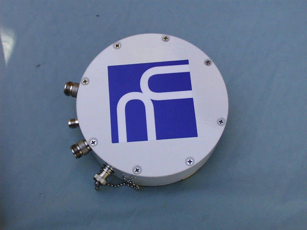
Utilicom Inc
Click to zoom
Application Details
- Equipment Class
- DSS - Part 15 Spread Spectrum Transmitter
- Date of Grant
- Mar 05, 2000
- Application Purpose
- Original Equipment
- Date of Application
- Oct 05, 1999
- Equipment Note
- Data transceiver
- Frequency Range
- 2407.78000000 - 2476.90000000
- Company
- Utilicom Inc
- Country
- United States
Documents & Files
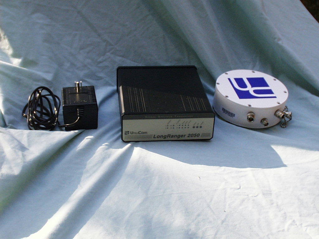
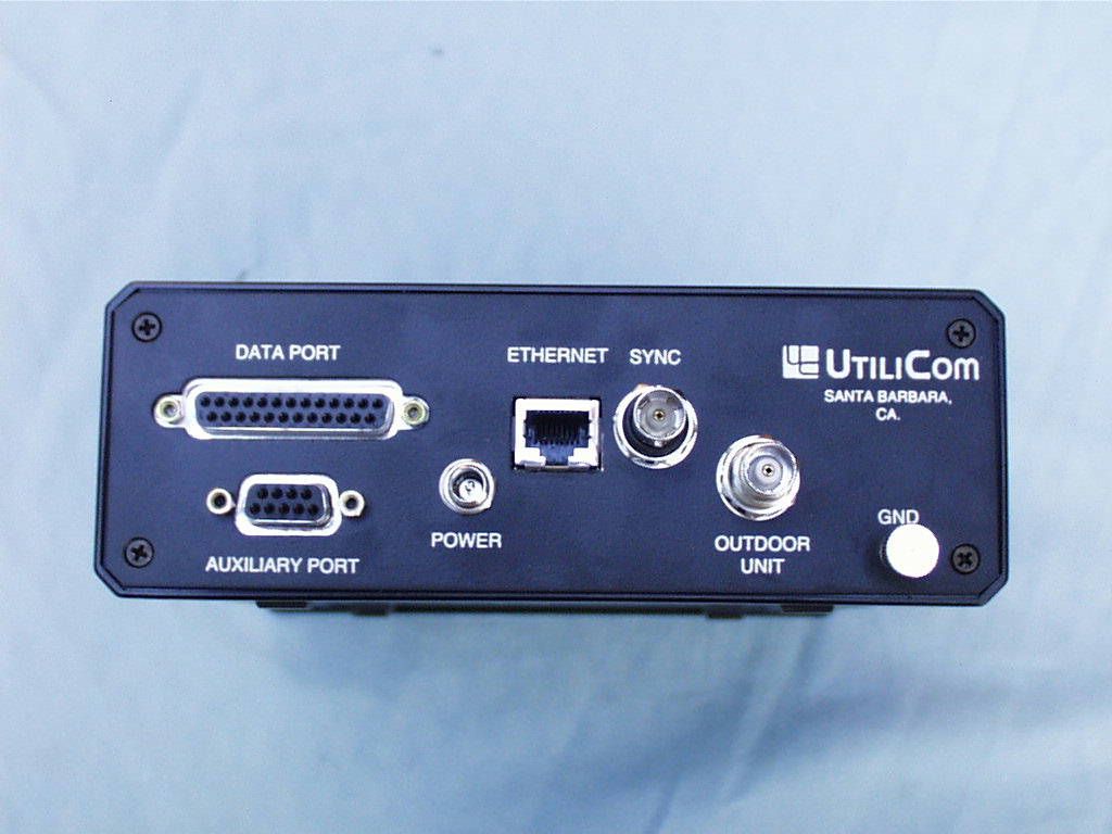
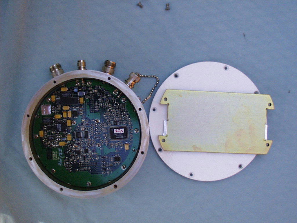
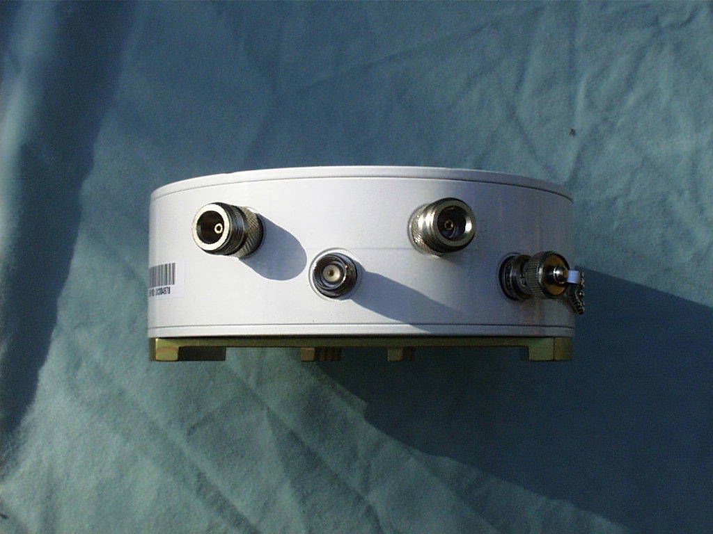
Document Text
Text extracted from the exhibit documents filed with the FCC. Open a document above to read the original.
Users Manual
SPREAD SPECTRUM COMMUNICATIONS U TILI O U U U LongRanger 2050 Operator’s Manual PRELIMINARY 18 October 1999 LongRanger 2050 Operator’s Manualii FCC Notice This equipment has been tested and found to comply with the limits for a Class B digital device, pursuant to Part 15 of the FCC Rules. These limits are designed to provide rea- sonable protection against harmful interference in a residential installation. This equip- ment generates, uses, and can radiate radio frequency energy and, if not installed and used in accordance with the instructions, may cause harmful interference to radio com- munications. However, there is no guarantee that interference will not occur in a particu- lar installation. If this equipment does cause harmful interference to radio or television reception, which can be determined by turning the equipment off and on, the user is encouraged to try to correct the interference by one or more of the following measures: •Reorient or relocate the receiving antenna. •Increase the separation between the equipment and receiver. •Connect the equipment into an outlet on a circuit different from that to which the receiver is connected. •Consult the dealer or an experienced radio/TV technician for help. Changes or modifications not expressly approved in writing by Utilicom Inc. may void the user’s authority to operate this equipment. Utilicom can not accept any financial or other responsibilities that may be the result of your use of this information, including direct, indi- rect, special, or consequential damages. There are no warranties extended or granted by this document. Refer to separate warranty documents for product warranty coverage and specifics. LongRanger 2050 Operator’s Manualiii TABLE OF CONTENTS 1INTRODUCTION................................................................................................................................. 1 2SPECIFICATIONS............................................................................................................................... 2 3INDOOR UNIT ..................................................................................................................................... 3 3.1F RONT PANEL.................................................................................................................................. 3 3.2R EAR PANEL.................................................................................................................................... 4 4OUTDOOR UNIT ................................................................................................................................. 6 5INITIAL INSTALLATION ................................................................................................................. 7 6COMMANDS ........................................................................................................................................ 8 6.1C OMMAND SYNTAX......................................................................................................................... 9 6.2R ADIO CONFIGURATIONS............................................................................................................... 10 6.3E DIT CONFIGURATION COMMANDS................................................................................................ 11 6.4C ONSOLE REDIRECTION COMMANDS............................................................................................. 15 6.5R ADIO TEST AND MONITORING COMMANDS................................................................................. 16 6.6M ISCELLANEOUS COMMANDS........................................................................................................ 17 1 INTRODUCTION The LongRanger 2050 is a Spread Spectrum radio operating in the “Industrial Scientific and Medical” (ISM) band from 2.400GHz to 2.4835 GHz. It provide a wireless, synchronous full duplex, point to point communications at a variety of speeds up to 768 Kbps. Spread Spectrum technology allows operation without a license with output power of up to 28 dBm. The LongRanger 2050 architecture separates the radio into two distinct sections: an Indoor Unit that interfaces with the user equipment, and a watertight Outdoor Unit, which is typically mounted in close proximity to the antenna. The two units are connected with a single coaxial cable, carrying the following signals: 1. DC voltage to power up the Outdoor Unit. 2. Reference frequency for the Outdoor Unit frequency synthesizer. 3. Encoded control signals to select the transmit/receive channels, calibration and built in test functions of the outdoor unit. 4. Intermediate Frequency (transmit and receive)) The cable connecting the Indoor and Outdoor unit can be an inexpensive coaxial cable since the Intermediate Frequency in the cable operates at 325 MHz. LongRanger 2050 Operator’s Manual2 2 SPECIFICATIONS RF Specifications RF Frequency Band2.400GHz to 2.4835 GHz RF Signal Bandwidth13.8 MHz RF ChannelsCenter frequency programmable in 512 KHz steps Transmitter Output PowerUp to 28 dBm (programmable) Modulation TypeBPSK or QPSK (programmable), direct sequence spread spectrum PN Code rate9.216 Mchip/sec PN Code Lengths11, 15, 31 or 63 (programmable) RF Data Rates (one way)146 Kbps to 1676 Kbps (see table below) Receiver Sensitivity (10 -6 BER) -95 dBm (@ 146 Kpbs) -84 dBm (@ 1676 Kbps) Transmit/Receive Turnaround< 150 us Data Interfaces Command PortRS-232 (DE9 connector) Primary Serial Data PortRS-232/EIA530/V.35 (DB25 connector) Ethernet Port10 BaseT Echelon LONWORKSRJ-45 Connector Diagnostic PortRS-232 (DE9 internal connector) Power Requirements Input Voltage+9 to +16 Volts DC (External AC adapter available) Power Consumption15 Watts maximum Operating Temperature -40 to +70 Degrees C Mechanical: Indoor Unit Dimensions6.8” wide x 2.3” high x 8.3” deep Indoor Unit Weight40 oz. Up/Down Converter Dimensions5.9” diameter x 1.75” high Up/Down Converter Weight48 oz. One Way RF Data Rates (Kbps) …
Text truncated - open the document above for the full version.
Users Manual
LongRanger 2050 Operator’s Manual PRELIMINARY 20 January 2000 LongRanger 2050 Operator’s Manualii FCC Notice This equipment has been tested and found to comply with the limits for a Class B digital device, pursuant to Part 15 of the FCC Rules. These limits are designed to provide rea- sonable protection against harmful interference in a residential installation. This equip- ment generates, uses, and can radiate radio frequency energy and, if not installed and used in accordance with the instructions, may cause harmful interference to radio com- munications. However, there is no guarantee that interference will not occur in a particu- lar installation. If this equipment does cause harmful interference to radio or television reception, which can be determined by turning the equipment off and on, the user is encouraged to try to correct the interference by one or more of the following measures: •Reorient or relocate the receiving antenna. •Increase the separation between the equipment and receiver. •Connect the equipment into an outlet on a circuit different from that to which the receiver is connected. •Consult the dealer or an experienced radio/TV technician for help. Changes or modifications not expressly approved in writing by UC Wireless Inc. may void the user’s authority to operate this equipment. UC Wireless can not accept any financial or other responsibilities that may be the result of your use of this information, including direct, indirect, special, or consequential damages. There are no warranties extended or granted by this document. Refer to separate warranty documents for product warranty coverage and specifics. LongRanger 2050 Operator’s Manualiii TABLE OF CONTENTS 1INTRODUCTION ..................................................................................................................................1 2SPECIFICATIONS ................................................................................................................................2 3INDOOR UNIT.......................................................................................................................................3 3.1F RONT P AN EL ................................................................................................................................3 3.2R EAR P ANEL ..................................................................................................................................4 4OUTDOOR UNIT...................................................................................................................................6 5INSTALLATION....................................................................................................................................7 5.1B EN CH C HECK O UT .......................................................................................................................7 5.2F IELD I NSTALLATION ....................................................................................................................7 5.3A NTENNA I NSTALLATION I NSTRUCTIONS : FCC RF E XPOSURE L IMITS .......................................9 6COMMANDS........................................................................................................................................10 6.1C OMMAND SYNTAX .....................................................................................................................10 6.2R ADIO C ONFIGURATIONS ............................................................................................................11 6.3E DIT CONFIGURATION COMMANDS ..............................................................................................13 6.4C ONSOLE R EDI RECTIO N C OMMANDS ..........................................................................................17 6.5R ADIO T ES T AN D M ONITORING C OMMANDS ...............................................................................18 6.6M ISCELLANEOUS COMMANDS .....................................................................................................19 1 INTRODUCTION The LongRanger 2050 is a Spread Spectrum radio operating in the “Industrial Scientific and Medical” (ISM) band from 2.400GHz to 2.4835 GHz. It provide a wireless, synchronous full duplex, point to point communications at a variety of speeds up to 768 Kbps. Spread Spectrum technology allows operation without a license with output power of up to 28 dBm. The LongRanger 2050 architecture separates the radio into two distinct sections: an Indoor Unit that interfaces with the user equipment, and a watertight Outdoor Unit, which is typically mounted in close proximity to the antenna. The two units are connected with a single coaxial cable, carrying the following signals: 1. DC voltage to power up the Outdoor Unit. 2. Reference frequency for the Outdoor Unit frequency synthesizer. 3. Encoded control signals to select the transmit/receive channels, calibration and built in test functions of the outdoor unit. 4. Intermediate Frequency (transmit and receive)) The cable connecting the Indoor and Outdoor unit can be an inexpensive coaxial cable since the Intermediate Frequency in the cable operates at 325 MHz. LongRanger 2050 Operator’s Manual2 2 SPECIFICATIONS RF Specifications RF Frequency Band2.400GHz to 2.4835 GHz RF Signal Bandwidth13.8 MHz RF ChannelsCenter frequency programmable in 512 KHz steps Transmitter Output PowerUp to 28 dBm (programmable) Modulation TypeBPSK or QPSK (programmable), direct sequence spread spectrum PN Code rate9.216 Mchip/sec PN Code Lengths11, 15, 31 or 63 (programmable) RF Data Rates (one way)146 Kbps to 1676 Kbps (see table below) Receiver Sensitivity (10 -6 BER) -95 dBm (@ 146 Kpbs) -84 dBm (@ 1676 Kbps) Transmit/Receive Turnaround< 150 us Data Interfaces Command PortRS-232 (DE9 connector) Primary Serial Data PortRS-232/EIA530/V.35 (DB25 connector) Ethernet Port10 BaseT Echelon LONWORKSRJ-45 Connector Diagnostic PortRS-232 (DE9 internal connector) Power Require…
Text truncated - open the document above for the full version.
Users Manual
LongRanger 2050 Operator’s Manual PRELIMINARY 20 January 2000 LongRanger 2050 Operator’s Manualii FCC Notice This equipment has been tested and found to comply with the limits for a Class B digital device, pursuant to Part 15 of the FCC Rules. These limits are designed to provide rea- sonable protection against harmful interference in a residential installation. This equip- ment generates, uses, and can radiate radio frequency energy and, if not installed and used in accordance with the instructions, may cause harmful interference to radio com- munications. However, there is no guarantee that interference will not occur in a particu- lar installation. If this equipment does cause harmful interference to radio or television reception, which can be determined by turning the equipment off and on, the user is encouraged to try to correct the interference by one or more of the following measures: •Reorient or relocate the receiving antenna. •Increase the separation between the equipment and receiver. •Connect the equipment into an outlet on a circuit different from that to which the receiver is connected. •Consult the dealer or an experienced radio/TV technician for help. Changes or modifications not expressly approved in writing by UC Wireless Inc. may void the user’s authority to operate this equipment. UC Wireless can not accept any financial or other responsibilities that may be the result of your use of this information, including direct, indirect, special, or consequential damages. There are no warranties extended or granted by this document. Refer to separate warranty documents for product warranty coverage and specifics. LongRanger 2050 Operator’s Manualiii TABLE OF CONTENTS 1INTRODUCTION ..................................................................................................................................1 2SPECIFICATIONS ................................................................................................................................2 3INDOOR UNIT.......................................................................................................................................3 3.1F RONT P AN EL ................................................................................................................................3 3.2R EAR P ANEL ..................................................................................................................................4 4OUTDOOR UNIT...................................................................................................................................6 5INSTALLATION....................................................................................................................................7 5.1B EN CH C HECK O UT .......................................................................................................................7 5.2F IELD I NSTALLATION ....................................................................................................................7 5.3A NTENNA I NSTALLATION I NSTRUCTIONS : FCC RF E XPOSURE L IMITS .......................................9 6COMMANDS........................................................................................................................................10 6.1C OMMAND SYNTAX .....................................................................................................................10 6.2R ADIO C ONFIGURATIONS ............................................................................................................11 6.3E DIT CONFIGURATION COMMANDS ..............................................................................................13 6.4C ONSOLE R EDI RECTIO N C OMMANDS ..........................................................................................17 6.5R ADIO T ES T AN D M ONITORING C OMMANDS ...............................................................................18 6.6M ISCELLANEOUS COMMANDS .....................................................................................................19 1 INTRODUCTION The LongRanger 2050 is a Spread Spectrum radio operating in the “Industrial Scientific and Medical” (ISM) band from 2.400GHz to 2.4835 GHz. It provide a wireless, synchronous full duplex, point-to-point communications at a variety of speeds up to 768 Kbps. Spread Spectrum technology allows operation without a license with output power of up to 28 dBm. The LongRanger 2050 architecture separates the radio into two distinct sections: an Indoor Unit that interfaces with the user equipment, and a watertight Outdoor Unit, which is typically mounted in close proximity to the antenna. The two units are connected with a single coaxial cable, carrying the following signals: 1. DC voltage to power up the Outdoor Unit. 2. Reference frequency for the Outdoor Unit frequency synthesizer. 3. Encoded control signals to select the transmit/receive channels, calibration and built in test functions of the outdoor unit. 4. Intermediate Frequency (transmit and receive)) The cable connecting the Indoor and Outdoor unit can be an inexpensive coaxial cable since the Intermediate Frequency in the cable operates at 325 MHz. LongRanger 2050 Operator’s Manual2 2 SPECIFICATIONS RF Specifications RF Frequency Band2.400GHz to 2.4835 GHz RF Signal Bandwidth13.8 MHz RF ChannelsCenter frequency programmable in 512 KHz steps Transmitter Output PowerUp to 28 dBm (programmable) Modulation TypeBPSK or QPSK (programmable), direct sequence spread spectrum PN Code rate9.216 Mchip/sec PN Code Lengths11, 15, 31 or 63 (programmable) RF Data Rates (one way)146 Kbps to 1676 Kbps (see table below) Receiver Sensitivity (10 -6 BER) -95 dBm (@ 146 Kpbs) -84 dBm (@ 1676 Kbps) Transmit/Receive Turnaround< 150 us Data Interfaces Command PortRS-232 (DE9 connector) Primary Serial Data PortRS-232/EIA530/V.35 (DB25 connector) Ethernet Port10 BaseT Echelon LONWORKSRJ-45 Connector Diagnostic PortRS-232 (DE9 internal connector) Power Require…
Text truncated - open the document above for the full version.
Cover Letter(s)
Thomas N. Cokenias EMC &Radio Approvals Test & Consulting Services for Commercial, Military, International Compliance P.O. Box 1086 El Granada, CA 94018 1 March 2000 FCC Laboratory 7435 Oakland Mills Road Columbia, MD 21046 Attention: Application Examiner Reviewing Engineer Re: Request for confidentiality per Section 0.459 of FCC Rules Applicant: Utilicom Inc. FCC ID: LFO-LR2050 To whom it may concern, Request is hereby submitted, on behalf of my client Utilicom Inc., to withhold from public review certain portions of the application for equipment certification for the referenced FCC identifier. In particular, the following sections of the application and report are requested to be kept confidential: Schematics Block diagrams Theory of operation Rationale for request for confidentiality: Utilicom has invested considerable time and materials in research and development to produce the referenced product. Disclosure of the confidential portions of this application to competitors would give them competitive advantage in developing similar products. The $135 fee for confidentiality has been submitted along with the fee for certification. If you have questions or need further information, please contact the undersigned. Sincerely, THOMAS N. COKENIAS EMC Consultant/Agent for Utilicom Inc. Tel 650 726 1263 fax 650 726 [email protected]
ID Label/Location Info
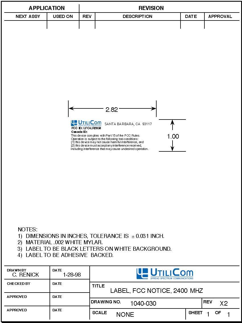
LR2050 FCC ID Label Area
RF Exposure Info
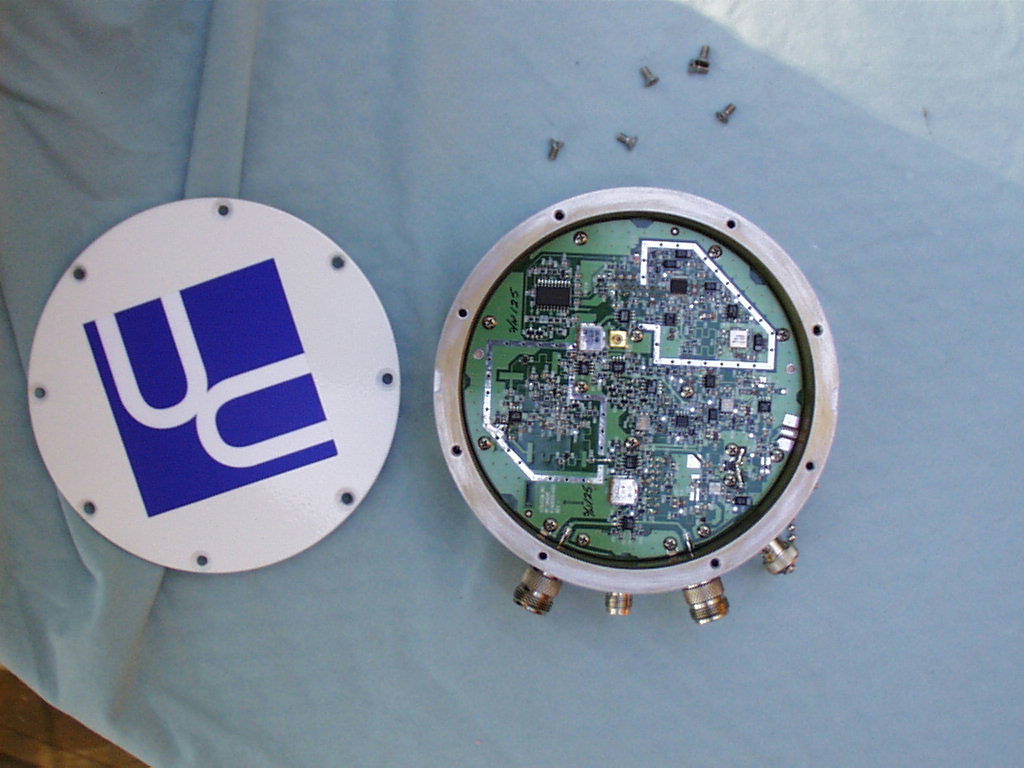
Utilicom LR2050 2.4 GHz Direct Sequence Spread Spectrum Radio FCC ID: LFO-LR2050 The following section will be added to the user manual: 5.3 Antenna Installation Instructions: FCC RF Exposure Limits Antennas used for these transmitters shall be professionally installed on permanent structures for outdoor operations. The installer is responsible for ensuring that the systems using high gain directional antennas are used exclusively for fixed, point-to-point operations. The installer shall mount all transmit antennas so as to comply with the limits for human exposure to radio frequency (RF) fields per paragraph 1.1307 of the Federal Communications Commission (FCC) Regulations . The FCC requirements incorporate limits for Maximum Permissible Exposure (MPE) in terms of electric field strength, magnetic field strength, and power density. Antenna installations shall be engineered so that MPE is limited to 1 mW/cm 2 , the more stringent limit for "uncontrolled environments". Table 2 below specifies the minimu m distance that must be maintained between the antenna and any areas where persons may have access, including rooftop walkways, sidewalks, as well as through windows and other RF-transparent areas behind which persons may be located. Table 2 Antenna Radiation Hazard Exposure, mW/cm2: 1.00 Max RF PowerTX AntennaMPE P, dBmG, dBiSafe Distance, cm 24.024.070.9 27.015.035.5 28.08.020* Basis of Calculations: E^2/3770 = S, mW/cm2 E, V/m = (Pwatts*Ggain*30)^.5/d, meters d = ((Pwatts*G*30)/3770*S))^0.5Pwatts*Ggain = 10^(PdBm-30+GdBi)/10) *NOTE: For mobile or fixed location transmitters, minimum separation distance is 20 cm, even if calculatio ns indicate MPE dista nce is le ss
Test Report
Utilicom Inc.FCC ID: LFO-LR2050 page 1 of 39 tel: 650-726-1263 fax: 650-726-1252 internet: [email protected] Thomas N. CokeniasEMC/RFI Specialist Test & Consulting Services for Commercial, Military, International Compliance P.O. Box 1086 El Granada CA94018 CERTIFICATION TEST REPORT FOR A 2400-2483.5 MHz DSSS TRANSCEIVER Applicant: Utilicom Inc. FCC ID:LFO-LR2050 Operating Frequency:2407.780 - 2476.900 MHz RF Output Power:0-28 dBm FCC Rule Part:15.247 Used For:Data link Power Source:120 AC Test Location:Compliance Consulting Services 951F Monterey Road Morgan Hill, CA 95087 All tests were performed by me or under my supervision. The LFO-LR2050 meets all emissions and modulation requirements specified under Parts 2 and 15 of the Commission’s Rules, as well as those specified in RSS-210 and RSP-100 for operation in Canada. THOMAS N. COKENIAS23 September 1998 Utilicom Inc.FCC ID: LFO-LR2050 page 2 of 39 tel: 650-726-1263 fax: 650-726-1252 internet: [email protected] EXHIBITS EXHIBIT A: Test Configurations and Rationale EXHIBIT B: Circuit Information (Confidentiality Requested per Rule section 0.459) B1: Schematics B2: Block Diagrams B3: Theory of Operation EXHIBIT C: Product Photographs EXHIBIT D: User Manual and FCC ID Label EXHIBIT E: Channel Frequency Assignment List EXHIBIT F: Description of Antennas and Antenna Connector Per 15.203 EXHIBIT G: Report of Measurements Utilicom Inc.FCC ID: LFO-LR2050 page 3 of 39 tel: 650-726-1263 fax: 650-726-1252 internet: [email protected] EXHIBIT A:Test Configurations and Rationale Utilicom Inc.FCC ID: LFO-LR2050 page 4 of 39 tel: 650-726-1263 fax: 650-726-1252 internet: [email protected] TEST CONFIGURATIONS AND RATIONALE The maximum allowed output power depended on data rate and antenna type being used. Limiting factors were power spectral density (PSD) at a given output power setting, on antenna gain, and on the amplitude of emission bandedge energy in restricted bands starting at 2483.5 MHz and 2390 MHz. Tests were performed using the following antennas: Antenna TypeMake and ModelGain omni rodMobilmark OD9-2400-248 dBi yagiCushcraft PC241515 dBi dish reflectorCal Amp dish 130094, feed 130013524 dBi Utilicom Inc.FCC ID: LFO-LR2050 page 5 of 39 tel: 650-726-1263 fax: 650-726-1252 internet: [email protected] SUMMARY OF MAXIMUM ALLOWED TRANSMITTER SETTINGS 8 dBi17 dBi25 dBiLR2050Rule Ref. Power level Setting P2P/P2MPP2P/P2MPP2P/P2MPP2P/P2MP Ch 530 dBm/28dBm 27 dBm/19dBm 24 dBm/11 dBm615.205 Ch 67 Ch 77 Ch 8INVALID Ch 9INVALID Ch107 Ch 117 Ch 127 Ch 138 Ch 2230 dBm/28dBm 27 dBm/19dBm 24 dBm/11 dBm1515.247(b)3 Ch 4011 Ch 4110 Ch 4210 Ch 4310 Ch 448 Ch 457 Ch 467 Ch 476 Ch 486 Ch 49- Ch 5030 dBm/28dBm 27 dBm/19dBm 24 dBm/11 dBm-15.205 These radios are all professionally installed and maintained, they are not sold to the general public or to hobbyists. Utilicom Inc.FCC ID: LFO-LR2050 page 6 of 39 tel: 650-726-1263 fax: 650-726-1252 internet: [email protected] EXHIBIT B:Circuit Information (Confidentiality Requested) B1: Schematics B2: Block Diagrams B3: Theory of Operation Utilicom Inc.FCC ID: LFO-LR2050 page 7 of 39 tel: 650-726-1263 fax: 650-726-1252 internet: [email protected] B1: Schematics Utilicom Inc.FCC ID: LFO-LR2050 page 8 of 39 tel: 650-726-1263 fax: 650-726-1252 internet: [email protected] B2: Block Diagrams Utilicom Inc.FCC ID: LFO-LR2050 page 9 of 39 tel: 650-726-1263 fax: 650-726-1252 internet: [email protected] EXHIBIT C:Theory of Operation Utilicom Inc.FCC ID: LFO-LR2050 page 10 of 39 tel: 650-726-1263 fax: 650-726-1252 internet: [email protected] EXHIBIT C:Product Photographs Utilicom Inc.FCC ID: LFO-LR2050 page 11 of 39 tel: 650-726-1263 fax: 650-726-1252 internet: [email protected] EXHIBIT D:User Manual and FCC ID Label Utilicom Inc.FCC ID: LFO-LR2050 page 12 of 39 tel: 650-726-1263 fax: 650-726-1252 internet: [email protected] EXHIBIT E: Channel Frequency Assignment List (from page 18 of User Manual) Channel Frequency Correspondence Channel Frequency (KHz)Channel Frequency (KHz)Channel Frequency (KHz) 52,407,780212,432,356372,456,932 62,409,316222,433,892382,458,468 72,410,852232,435,428392,460,004 82,412,388242,436,964402,461,540 92,413,924252,438,500412,463,076 102,415,460262,440,036422,464,612 112,416,996272,441,572432,466,148 122,418,532282,443,108442,467,684 132,420,068292,444,644452,469,220 142,421,604302,446,180462,470,756 152,423,140312,447,716472,472,292 162,424,676322,449,252482,473,828 172,426,212332,450,788492,475,364 182,427,748342,452,324502,476,900 192,429,284352,453,860 202,430,820362,455,396 Number of Non-Overlapping Channels Suggested Channel AllocationFrequency Separation 35, 27, 4933,792 45, 20, 35, 5023,040 55, 16, 27, 38, 4916, 896 65, 14, 23, 32, 41, 5013,824 Utilicom Inc.FCC ID: LFO-LR2050 page 13 of 39 tel: 650-726-1263 fax: 650-726-1252 internet: [email protected] EXHIBIT F:Description of Antennas and Antenna Connector Per FCC Rule Para. 15.203 Note: EUT is professionally installed, therefore standard N-type antenna and cable connectors are used. Power levels are also set by the installer. Antenna TypeMake and ModelGain omni rodMobilmark OD9-2400-248 dBi yagiCushcraft PC241515 dBi dish reflectorCal Amp dish 130094, feed 130013524 dBi Utilicom Inc.FCC ID: LFO-LR2050 page 14 of 39 tel: 650-726-1263 fax: 650-726-1252 internet: [email protected] EXHIBIT G: Report of Measurements Utilicom Inc.FCC ID: LFO-LR2050 page 15 of 39 tel: 650-726-1263 fax: 650-726-1252 internet: [email protected] EMISSIONS TEST REPORT FOR A LOW POWER TRANSMITTER I. GENERAL INFORMATION Requirement:FCC: 47CFR, Parts 2 and 15 Industry Canada: RSS-210 and RSP-100 Applicant:Utilicom Inc. 323 Love Place Goleta, CA 93117 Product ID:U.S.: FCC ID: LFO-LR2050 Model Numbers:LR2050, LR2040 II. DESCRIPTION OF EQUIPMENT UNDER TEST (EUT) The Utilicom radios are 2400 - 2483.5 MHz direct sequence spread spectrum (DSSS) transceiver links for data transmission. III. TEST L…
Text truncated - open the document above for the full version.
Test Report
Sheet4 COMPLIANCE ENGINEERING SERVICES, INC. Radiated Emissions 08/27/99 15.209 Jesse SaldivarC site (1.5 Meter) UtilicomLR2050 w/ 0D9-2400 Antenna CH:50f o= 2476.9 MHz F(MHz) READING AF CL A MP DIST HPF TOTAL LIMIT MARGIN (dBuV) (dB) (dB) (dB) (dB) (dB) (dBuV/m) (dBuV/m) (dB) Pk A vg Pk A vg Pk A vg Pk A vg 4954.06 55.41 50.34 35.2 5.25 -35 -10 1 51.41 46.34 74 54 -22.6 -7.66 7430.55 47.5 35.9 41.5 7 -35 -10 1 51.55 39.95 74 54 -22.5 -14.1 9907.62 45.07 34.1 41.8 7.87 -35 -10 1 50.29 39.32 74 54 -23.7 -14.7 12384.65 45.73 34 42 8.75 -35 -10 1 52.03 40.3 74 54 -22 -13.7 14861.68 48.15 37.21 46.5 10.5 -35 -20 1 51.15 40.21 74 54 -22.9 -13.8 17338.71 51.1 38.7 46.4 11.37 -35 -20 1 54.87 42.47 74 54 -19.1 -11.5 NOTE: ALL READINGS ARE VERTICA L A NALYZER SETTINGS DIST : Correction to extrapolate reading to 3m specification distance Res bw Avg. bw 1.0M measurement distance: -10.45dB PEAK(P k ) : 1MHz 1MHz AF : Antenna Factor A VERAGE(Avg): 1MHz 10Hz AMP : Pre-amp gain CL : Cable loss HPF : High pass filter insertion loss (4.6GHz) FSY (S/N: 001) Page 1
Test Report
Sheet4 COMPLIANCE ENGINEERING SERVICES, INC. Radiated Emissions 08/27/99 15.209 Jesse SaldivarC site (1.5 Meter) UtilicomLR2050 w/ 0D9-2400 Antenna CH:05f o= 2407.78 MHz F(MHz) READING AF CL A MP DIST HPF TOTAL LIMIT MARGIN (dBuV) (dB) (dB) (dB) (dB) (dB) (dBuV/m) (dBuV/m) (dB) Pk A vg Pk A vg Pk A vg Pk A vg 4815.56 54.9 50.88 35.2 5.25 -35 -10 1 50.9 46.88 74 54 -23.1 -7.12 7223.34 51 42.8 41.5 7 -35 -10 1 55.05 46.85 74 54 -19 -7.15 9631.12 50.58 45.42 41.8 7.87 -35 -10 1 55.8 50.64 74 54 -18.2 -3.36 12038.9 47.34 34.43 42 8.75 -35 -20 1 44.09 31.18 74 54 -29.9 -22.8 14446.68 48.55 37.05 46.5 10.5 -35 -20 1 51.55 40.05 74 54 -22.5 -14 16854.44 50.92 38.52 46.4 11.37 -35 -20 1 54.69 42.29 74 54 -19.3 -11.7 NOTE: ALL READINGS ARE VERTICA L A NALYZER SETTINGS DIST : Correction to extrapolate reading to 3m specification distance Res bw Avg. bw 1.0M measurement distance: -10.45dB PEAK(P k ) : 1MHz 1MHz AF : Antenna Factor A VERAGE(Avg): 1MHz 10Hz AMP : Pre-amp gain CL : Cable loss HPF : High pass filter insertion loss (4.6GHz) FSY (S/N: 001) Page 1
Test Report
Sheet4 COMPLIANCE ENGINEERING SERVICES, INC. Radiated Emissions 08/27/99 15.209 Jesse SaldivarC site (1.5 Meter) UtilicomLR2050 w/ 0D9-2400 Antenna CH:22f o= 2433.89 MHz F(MHz) READING AF CL A MP DIST HPF TOTAL LIMIT MARGIN (dBuV) (dB) (dB) (dB) (dB) (dB) (dBuV/m) (dBuV/m) (dB) Pk A vg Pk A vg Pk A vg Pk A vg 4867.78 65.05 61.7 35.2 5.25 -35 -10 1 61.05 57.7 74 54 -13 3.7 7301.67 55.3 47.5 41.5 7 -35 -10 1 59.35 51.55 74 54 -14.7 -2.45 9735.56 52.36 47.31 41.8 7.87 -35 -10 1 57.58 52.53 74 54 -16.4 -1.47 12169.45 46.13 34.13 42 8.75 -35 -10 1 52.43 40.43 74 54 -21.6 -13.6 14603.34 49.44 37.13 46.5 10.5 -35 -20 1 52.44 40.13 74 54 -21.6 -13.9 17037.23 50.24 38.62 46.4 11.37 -35 -20 1 54.01 42.39 74 54 -20 -11.6 TP L=14: 4867.78 62.3 57.44 35.2 5.25 -35 -10 1 58.3 53.44 74 54 -15.7 -0.56 NO…
Text truncated - open the document above for the full version.
Contact Information
Applicant
Dean Gaston(President)
805 964-5848Fax: 805 964-5706
Technical Contact
T.N. Cokenias ConsultingThomas N Cokenias
[email protected]650 726 1263
355 El Granada Blvd · El Granada, California · United States
Non-Technical Contact
T.N. CokeniasThomas N Cokenias
[email protected]650 726 1263
Test Firm
Compliance Certification Services IncSteve Cheng
Technical Specifications
| # | Rule Parts | Frequency Range | Power Output |
|---|---|---|---|
| 1 | 15C | 2.41 GHz - 2.48 GHz | 630.90 mW |
Other Applications from Utilicom Inc

LFO-WR2411
Sep 18, 2001DSSS Transceiver, Model No:VIP 110-24
Equipment Class
DSS - Part 15 Spread Spectrum TransmitterLFO-ISM2400
Oct 29, 1995WLAN Maximum output power: 50 mW
Equipment Class
DSS - Part 15 Spread Spectrum TransmitterLFO-ISM900
Dec 21, 1994Maximum Output Power: 800 mW
Equipment Class
DSS - Part 15 Spread Spectrum Transmitter